Table of Contents
Advertisement
Advertisement
Table of Contents

Related Manuals for HP Thin Client T740


Summary of Contents for HP Thin Client T740
- Page 1 Hardware Reference Guide HP Thin Client...
- Page 2 © Copyright 2016 HP Development Company, The information contained herein is subject to L.P. change without notice. The only warranties for HP products and services are set forth in the First Edition: June 2016 express warranty statements accompanying such products and services. Nothing herein...
- Page 3 About This Book WARNING! Text set off in this manner indicates that failure to follow directions could result in bodily harm or loss of life. CAUTION: Text set off in this manner indicates that failure to follow directions could result in damage to equipment or loss of information.
- Page 4 About This Book...
-
Page 5: Table Of Contents
Connecting the AC power cord ..........................8 Securing the thin client ............................9 Mounting and orienting the thin client ........................9 HP Quick Release ..........................9 Supported mounting options ......................11 Supported orientation and placement ..................... 13 Non-supported placement ........................ 14 Routine thin client care ............................ - Page 6 Appendix B Shipping information ........................28 Shipping preparation ............................28 Important service repair information ........................28 Appendix C Accessibility ..........................29 Supported assistive technologies ........................29 Contacting support .............................. 29 Index ................................30...
-
Page 7: Product Features
Various options are available for your thin client. For more information about some of the available options, go to the HP website at http://www.hp.com and search for your specific thin client. -
Page 8: Front Panel Components
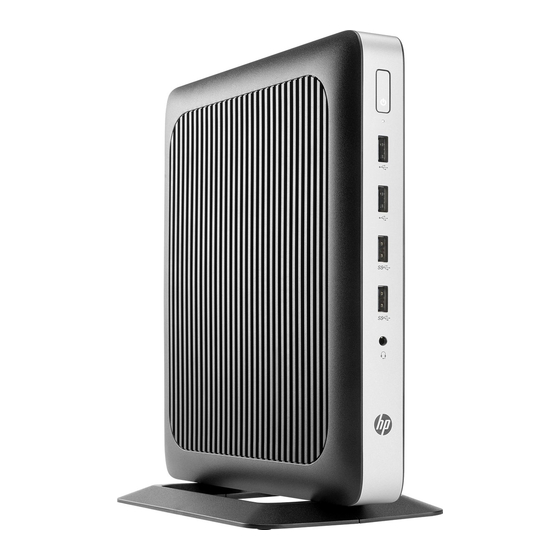
Front panel components For more information, go to http://www.hp.com/go/quickspecs and search for your specific thin client to find the QuickSpecs. Item Component Item Component Headset jack Flash drive activity LED USB 3.0 ports (2) Power button USB 2.0 ports (2) -
Page 9: Rear Panel Components
Rear panel components For more information, go to http://www.hp.com/go/quickspecs/ and search for your specific thin client to find the QuickSpecs. Item Component Item Component Ethernet RJ-45 port Audio-out (headphone)/Audio-in (microphone) combo jack PS/2 keyboard port Optional port. If used, may provide dual coaxial cable... -
Page 10: Serial Number Location
Serial number location Every thin client includes a unique serial number located as shown in the following illustration. Have this number available when contacting HP customer service for assistance. Chapter 1 Product features... -
Page 11: Setup
To reduce the risk of serious injury, read the Safety & Comfort Guide. It describes proper workstation setup, posture, and health and work habits for thin client users, and provides important electrical and mechanical safety information. The Safety & Comfort Guide is located on the HP website at http://www.hp.com/ergo. WARNING! Energized parts inside. -
Page 12: Attaching The Stand
Attaching the stand CAUTION: Unless the thin client is mounted with the HP Quick Release, it must be operated with the stand attached to ensure proper airflow around the thin client. Adjusting the stand The stand can be adjusted into two configurations: square for the horizontal position and rectangular for the vertical position. - Page 13 Position the stand over the bottom of the thin client and line up the captive screws in the stand with the screw holes in the thin client. Tighten the captive screws securely. Attach the stand to the right side of the thin client to use it in the horizontal orientation. ●...
-
Page 14: Connecting The Ac Power Cord
NOTE: An optional Quick Release mounting bracket is available from HP for mounting the thin client to a wall, desk, or swing arm. When the mounting bracket is used, do not install the thin client with the I/O ports oriented towards the ground. -
Page 15: Securing The Thin Client
Securing the thin client These thin clients are designed to accept a security cable. The security cable prevents unauthorized removal of the thin client, as well as preventing access to the secure compartment. To order this option, go to the HP website at http://www.hp.com... - Page 16 To use the HP Quick Release: Using four 10 mm screws included in the mounting device kit, attach one side of the HP Quick Release to the thin client as shown in the following illustration. Using four screws included in the mounting device kit, attach the other side of the HP Quick Release to the device to which you will mount the thin client.
-
Page 17: Supported Mounting Options
NOTE: When attached, the HP Quick Release automatically locks in position. You only need to slide the lever to one side to remove the thin client. Supported mounting options The following illustrations demonstrate some of the supported mounting options for the mounting bracket. - Page 18 On a wall: ● Under a desk: ● Chapter 2 Setup...
-
Page 19: Supported Orientation And Placement
You must adhere to the HP-supported orientation to ensure your thin clients function properly. Unless the thin client is mounted with the HP Quick Release, it must be operated with the stand attached to ensure proper airflow around the thin client. -
Page 20: Non-Supported Placement
The thin client may be placed under a monitor stand with at least 2.54 cm (1 in) clearance: ● Non-supported placement HP does not support the following placements for the thin client: CAUTION: Non-supported placement of thin clients could result in operation failure and/or damage to the devices. -
Page 21: Routine Thin Client Care
Keep the thin client away from excessive moisture, direct sunlight, and extreme heat and cold. For ● information about the recommended temperature and humidity ranges for the thin client, go to http://www.hp.com/go/quickspecs. Keep liquids away from the thin client and keyboard. ●... -
Page 22: Hardware Changes
ALWAYS operate the thin client with the access panel in place. In addition to enhancing safety, the access panel may provide important instructions and identification information, which may be lost if the access panel is not used. DO NOT use any access panel except the one that is provided by HP for use with this thin client. - Page 23 Disconnect the AC power cord from the AC outlet, and disconnect any external devices. CAUTION: Regardless of the power-on state, voltage is always present on the system board as long as the system is plugged into an active AC outlet. You must disconnect the AC power cord to avoid damage to the internal components of the thin client.
-
Page 24: Replacing The Access Panel
Replacing the access panel To replace the access panel: Position the access panel on the chassis, approximately 6 mm (.24 in) inside the edge of the chassis. Slide the panel toward the front of the chassis (1) until it locks into place. Move the access panel latch (2) to the left to secure the access panel. -
Page 25: Locating Internal Components
Locating internal components Item Component Item Component Battery USB 3.0 port System memory DIMM1 M.2 socket for a 42 mm, 60 mm, or 80 mm M.2 primary storage module System memory DIMM2 M.2 socket for a 42 mm M.2 secondary storage module CMOS button Locating internal components... -
Page 26: Replacing An M.2 Storage Module
Replacing an M.2 storage module Two M.2 storage module sockets can be installed in the thin client: A 42 mm, 60 mm, or 80 mm M.2 primary storage module may be installed in one socket. ● A 42 mm M.2 secondary storage module may be installed in the other socket. ●... - Page 27 Pull the screw kit off of the storage module and attach it to the replacement storage module. Slide the new storage module into the M.2 socket on the system board and press the module connectors firmly into the socket. NOTE: A storage module can be installed in only one way.
-
Page 28: Removing And Replacing The Battery
Press the storage module down and use a screwdriver to tighten the screw and secure the module to the system board. Replace and latch the access panel, and then reinstall the rear I/O panel. See Removing and replacing the access panel on page Replace the thin client stand. -
Page 29: Installing An Internal Usb Flash Drive
Reconnect the AC power cord and turn on the thin client. Lock any security devices that were disengaged when the thin client access panel was removed. HP encourages customers to recycle used electronic hardware, HP original print cartridges, and rechargeable batteries. For more information about recycling programs, go to http://www.hp.com... - Page 30 Remove the stand from the thin client. Lay the unit flat on a stable surface with the right side up. Remove the thin client access panel. See Removing and replacing the access panel on page WARNING! To reduce risk of personal injury from hot surfaces, allow the internal system components to cool before you touch them.
-
Page 31: Upgrading System Memory
Upgrading system memory The memory socket on the system board is populated with one memory module. To achieve the maximum memory support, you can populate each memory socket with up to 16 GB of memory each (32 GB total). For proper system operation, the memory module must adhere to the following specifications: Industry-standard 260-pin Small Outline DIMM (SODIMM) ●... - Page 32 Position the unit flat on a stable surface with the right side up. Remove the thin client access panel. See Removing and replacing the access panel on page WARNING! To reduce risk of personal injury from hot surfaces, allow the internal system components to cool before you touch them.
-
Page 33: Appendix A Electrostatic Discharge
● Use a portable field service kit with a folding static-dissipating work mat. ● If you do not have any of the suggested equipment for proper grounding, contact an HP authorized dealer, reseller, or service provider. NOTE: For more information about static electricity, contact an HP authorized dealer, reseller, or service provider. -
Page 34: Appendix B Shipping Information
For environmental nonoperating ranges, go to http://www.hp.com/go/quickspecs. Important service repair information In all cases, remove and safeguard all external options before returning the thin client to HP for repair or exchange. In countries that support customer mail-in repair by returning the same unit to the customer, HP makes every effort to return the repaired unit with the same internal memory and flash modules that were sent. -
Page 35: Appendix C Accessibility
Accessibility HP designs, produces, and markets products and services that can be used by everyone, including people with disabilities, either on a stand-alone basis or with appropriate assistive devices. Supported assistive technologies HP products support a wide variety of operating system assistive technologies and can be configured to work with additional assistive technologies. -
Page 36: Index
Index thin client onto HP Quick AC power cord connection 8 Release 9 security cable, installing 9 access panel USB flash drive 23 serial number location 4 removing 16 internal components 19 service repair 28 replacing 18 shipping preparation 28...
Need help?
Do you have a question about the Thin Client T740 and is the answer not in the manual?
Questions and answers