
Related Manuals for TelcoBridges 3200 Series Gateway Standalone


Summary of Contents for TelcoBridges 3200 Series Gateway Standalone
-
Page 1: Installation Guide
Installation Guide 3200 Series Gateway Standalone & 3200 Series Gateway 1+1 June 1, 2016... - Page 2 TMG7800-DS3+1, TMG7800-STM1+1, Tdev, TMP800, TMP6400, TMP6400-CTRL, TMP6400-TMS, Tmonitor, TM1000, TM3000, Toopack, Toolpack API, TB640, TB-8, TB-16, and TB-Video, are trademarks of TelcoBridges Inc. All other trademarks are the property of their owners. This information is subject to change without notice.
-
Page 3: About This Guide
Preface About this Guide This guide provides installation, and setup procedures for the 3200 series standalone and 3200 series 1+1 systems. Conventions Terminology Description 3200 series gateway This term is used when a description applies to both the 3200 series standalone system and 3200 series 1+1 system. - Page 4 3200 series +1 and 1+1 Patch Panel(s). If you are installing a 1+1 System read and follow the instructions provided in those sections and pages. Contact Us If you have comments about this guide or any other TelcoBridges technical documentation, please send an email to marketing@telcobridges.com.
-
Page 5: Table Of Contents
Table of Contents Table of Contents Section 1 Introduction........................1 Recognizing a 3200 Series Standalone versus a 3200 Series 1+1 System .......2 1.1.1 3200 Series Standalone .....................2 1.1.2 3200 Series 1+1 System ....................2 1.1.3 Product Images ........................2 Installation Prerequisites .....................4 Preventing Electrostatic Discharge Damage...............5 Recommended Reading......................6 Section 2... - Page 6 3200 Series Standalone and 3200 Series 1+1 System Installation Guide 2.6.1 Reconfigure a Standalone Unit as a Primary Unit in an 3200 Series 1+1 System....41 2.6.2 Install the 3200 Series +1 Unit on the Equipment Rack ............44 2.6.3 Install a 1+1 Patch Panel ....................44 2.6.4 Connect to the 3200 Series 1+1 Management Interface...........45 2.6.5...
-
Page 7: Introduction
Section 1 Introduction This chapter provides an introduction to the installation and setup for the following configurations: 3200 Series Standalone: Single gateway unit operation in standalone mode. 3200 Series 1+1 System: 3200 series unit operating in conjunction with a 3200 series +1 unit, and 1+1 patch panel(s). -
Page 8: Recognizing A 3200 Series Standalone Versus A 3200 Series 1+1 System
3200 Series Standalone and 3200 Series 1+1 System Installation Guide Recognizing a 3200 Series Standalone versus a 3200 Series 1+1 System 1.1.1 3200 Series Standalone The 3200 series standalone consists of one telecom unit. The front and rear views are shown in figure 1.1 on page 2. - Page 9 Introduction 1+1 Patch Panel (TE) front view Gateway Gateway rear view 1+1 Patch Panel (DS3) BITS BITS BITS front view Gateway Gateway 1+1 Network Gateway 1+1 Network Network Gateway 1+1 Network 1+1 Patch Panel (STM1) BITS BITS BITS Gateway Gateway front view Main Main...
-
Page 10: Installation Prerequisites
3200 Series Standalone and 3200 Series 1+1 System Installation Guide Installation Prerequisites For the installation to proceed without interruption, it is important that you verify that you have all necessary materials on hand. 3200 Series Standalone 3200 Series 1+1 System Adequate space for the installation of the Adequate space for the installation of your 3200 Series Standalone. -
Page 11: Preventing Electrostatic Discharge Damage
Introduction Preventing Electrostatic Discharge Damage Electrostatic discharge (ESD) can damage equipment and impair electrical circuitry. It may occur if electronic printed circuit cards are improperly handled and may cause complete or intermittent failure. Always follow ESD prevention procedures when removing and replacing modules: •... -
Page 12: Recommended Reading
This document assumes that you have a clear understanding of the installation of the equipment described in this document and have been trained to work with the equipment.If you have any technical questions, TelcoBridges TB Support (technical support team) can be reached at the following numbers or an email can be sent to: support@telcobridges.com. -
Page 13: Installing The Equipment
Section 2 Installing the Equipment This chapter provides information about the following topics: • Section 2.1 “Package Contents” • Section 2.2 “Rack Mounting the 3200 Series Standalone or 3200 Series 1+1 System” • Section 2.3 “Choosing your Connection Procedures” • Section 2.4 “3200 Series Standalone System”... -
Page 14: Package Contents
3200 Series Standalone and 3200 Series 1+1 System Installation Guide Package Contents Depending on your system requirements, you may receive one or more of the following items: • Section 2.1.1 “3200 Series Standalone Package Contents” on page 8. • Section 2.1.2 “3200 Series 1+1 System Package Contents” on page 9. •... -
Page 15: 3200 Series 1+1 System Package Contents
Installing the Equipment 2.1.2 3200 Series 1+1 System Package Contents TMG3200, TSG3200, TMGIP3200 In the box, you will find the following items: • One 3200 series unit: TMG3200 (TMG3200-TE, TMG3200-DS3, or TMG3200-STM1), or TSG3200 (TSG3200-TE, TSG3200-DS3), or TMGIP3200. See figure 1.1 on page 2. •... - Page 16 3200 Series Standalone and 3200 Series 1+1 System Installation Guide Not included • A 19” equipment rack. The 3200 +1 series unit must be installed on a 19” wide equipment rack. 1+1 Patch Panels 1+1 patch panels are required for the proper connection of the 3200 series 1+1 system, and are automatically included when a 3200 +1 series unit is ordered.
-
Page 17: Rack Mounting The 3200 Series Standalone Or 3200 Series 1+1 System
Installing the Equipment Rack Mounting the 3200 Series Standalone or 3200 Series 1+1 System The 3200 series equipment is mounted on a customer provided equipment rack using the mounting hardware packaged in the box. 2.2.1 Prerequisites To rack mount the equipment, you will need: •... - Page 18 3200 Series Standalone and 3200 Series 1+1 System Installation Guide Mounting the 3200 Series 1+1 System: Mount the 3200 series unit as mentioned above. Install the 3200 series +1 unit below the 3200 series unit, as shown in Figure 2.1 on page 12. Install the patch panel below the 3200 series +1 unit, as shown in Figure 2.1 on page 12.
-
Page 19: Choosing Your Connection Procedures
Installing the Equipment Choosing your Connection Procedures Use the following diagram to guide you to the appropriate section, based on your chosen installation. Choosing Your Setup 3200 Series 3200 Series 1+1 Adding a Unit Standalone System I am setting I am setting up a I am adding up a 3200 Series... -
Page 20: 3200 Series Standalone System
3200 Series Standalone and 3200 Series 1+1 System Installation Guide 3200 Series Standalone System If you are here, you have a 3200 series unit that you will setup as a standalone system. This section covers the following procedures for a 3200 series standalone system: •... -
Page 21: Connecting To The 3200 Series Gateway Management Interface
Installing the Equipment 2.4.1 Connecting to the 3200 Series Gateway Management Interface The 3200 series gateway management interface enables administrators to perform management tasks on the 3200 series unit. Prerequisites To communicate with the management interface, the following is needed: •... -
Page 22: Connecting To A Voip Network
3200 Series Standalone and 3200 Series 1+1 System Installation Guide 2.4.2 Connecting to a VoIP Network The 3200 series gateway features dual GigE ports for connection to different VoIP networks. This provides an access point to manage VoIP traffic. Should one of the IP networks fail, the 3200 series gateway will continue to manage VoIP traffic using the alternate network. -
Page 23: Connecting To The Pstn
Installing the Equipment 2.4.3 Connecting to the PSTN The 3200 series gateway features a variety of interfaces to the PSTN network. Note This section only applies to the TMG3200 and TSG3200 systems. Prerequisites To connect to the PSTN network, you must comply with one of the following: •... -
Page 24: Scsi Interface (T1/E1) For The 3200-Te
3200 Series Standalone and 3200 Series 1+1 System Installation Guide 2.4.3.1 SCSI Interface (T1/E1) for the 3200-TE A 3200-TE and SCSI patch panel enables the connection to T1/E1 lines. The termination impedance is set at 120 ohms. It is possible to connect an external balun in order to convert to 75 ohms. Note All ports may not be active. - Page 25 Installing the Equipment MGMT0 48-63 16-31 VOIP 32-47 0-15 SCSI patch panel 1 (rear view) 16-31 0-15 SCSI patch panel 2 (rear view) 16-31 0-15 SCSI patch panel (front view) Figure 2.4 3200-TE with SCSI connectors...
-
Page 26: Dual Bnc Interface (Ds3) For The 3200-Ds3
3200 Series Standalone and 3200 Series 1+1 System Installation Guide 2.4.3.2 Dual BNC Interface (DS3) for the 3200-DS3 A 3200-DS3 with 3 sets of BNC connectors enables the connection to DS3 lines. See Figure 2.5 on page 20. Note All ports may not be active. DS3 ports are activated by software license; the number of active ports depends on the licenses purchased. -
Page 27: Optical Interface (Oc3/Stm-1) For The 3200-Stm1
Installing the Equipment 2.4.3.3 Optical Interface (OC3/STM-1) for the 3200-STM1 A 3200-STM-1, with one main and one backup OC3 or STM1 port enables connection to OC3/STM1 lines. See Figure 2.6 on page 21. Refer to Table 2.3 on page 21 for a listing of optical interfaces. The default SFP module for OC3/STM1 connection is SMF, intermediate reach, (SFP-OC3-IR1) 1310 nm with LC type connectors. -
Page 28: Grounding The Equipment Chassis
3200 Series Standalone and 3200 Series 1+1 System Installation Guide 2.4.4 Grounding the Equipment Chassis As a standard safety practice, the chassis of the 3200 series gateway must be properly grounded to protect against any contact with an electrical fault condition. It is recommended that the chassis be connected to an earth ground. -
Page 29: Powering Up
Installing the Equipment 2.4.5 Powering Up The 3200 series gateway is furnished with two AC or DC power connections. Only once all other equipment installation work has been completed should the 3200 series gateway be powered up. 2.4.5.1 Connecting to AC Power Prerequisites To power the 3200 series gateway, you will need: •... -
Page 30: Connecting To Dc Power
3200 Series Standalone and 3200 Series 1+1 System Installation Guide 2.4.5.2 Connecting to DC Power The 3200 series gateway DC model is furnished with two DC power connection ports. In addition, each DC powered unit is supplied with two DC power cables. Fuse and Cabling Requirements 16 AWG wiring must be used and the 48V supply must be protected with a customer provided 5A 48V fuse. -
Page 31: Start Up
Installing the Equipment 2.4.6 Start Up The first time that you connect to a 3200 series gateway, the web portal will appear and you will be asked to select how you would like to configure the 3200 series gateway. You will want to be sure to set the role as a 3200 series standalone. -
Page 32: 3200 Series 1+1 System
3200 Series Standalone and 3200 Series 1+1 System Installation Guide 3200 Series 1+1 System If you are here, you are installing a 3200 series 1+1 system. This section covers the following procedures: • Section 2.5.1 “Connecting to the 3200 Series 1+1 System Management Interfaces” on page 27. •... -
Page 33: Connecting To The 3200 Series 1+1 System Management Interfaces
Installing the Equipment 2.5.1 Connecting to the 3200 Series 1+1 System Management Interfaces The management interface enables administrators to perform management tasks on a 3200 series 1+1 system. Prerequisites To communicate with the management interface, the following is needed: • Two CAT5 Ethernet cables with RJ45 male-male terminations. -
Page 34: Connecting To The Control Network
3200 Series Standalone and 3200 Series 1+1 System Installation Guide 2.5.2 Connecting to the Control Network The 3200 series control network enables a 3200 series unit to be connected to a 3200 series +1 unit, allowing for a sharing of system resources. Prerequisites To connect to the control network, you will need: •... -
Page 35: Connecting The 3200 Series 1+1 System Voip Network(S)
Installing the Equipment 2.5.3 Connecting the 3200 Series 1+1 System VoIP Network(s) Each 3200 series unit and 3200 series +1 unit features dual GigE ports for connection to different VoIP networks. This provides an access point to manage VoIP traffic. Should one of the IP networks fail, the 3200 series 1+1 system will continue to manage VoIP traffic using the alternate network. -
Page 36: Connecting To The Pstn In A 3200 Series 1+1 System
3200 Series Standalone and 3200 Series 1+1 System Installation Guide 2.5.4 Connecting to the PSTN in a 3200 Series 1+1 System Note This section only applies to the TMG3200 and TSG3200 systems. The 3200 Series 1+1 system features a variety of interfaces to the PSTN network. Prerequisites To connect to the PSTN network, you must comply with one of the following: •... -
Page 37: Scsi Interface (T1/E1) For The 3200-Te And 3200-Te+1
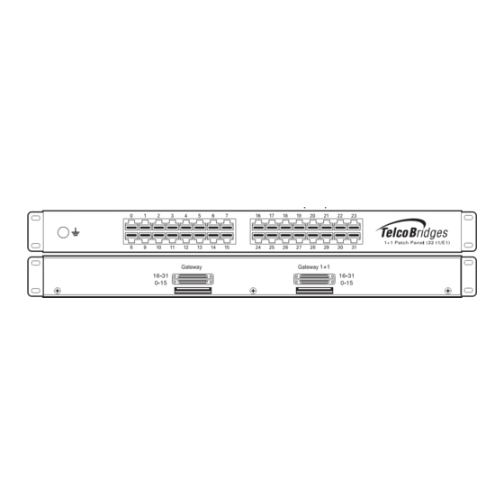
Installing the Equipment 2.5.4.1 SCSI Interface (T1/E1) for the 3200-TE and 3200-TE+1 A 3200-TE and 3200-TE+1 with SCSI patch panels enables the connection to T1/E1 lines. The termination impedance is set at 120 ohms. It is possible to connect an external balun in order to convert to 75 ohms. - Page 38 3200 Series Standalone and 3200 Series 1+1 System Installation Guide 3200-TE MGMT0 VOIP 3200-TE+1 MGMT0 VOIP rear view Gateway Gateway front view From Network Figure 2.13 3200-TE and 3200-TE+1 connecting to the TDM 1+1 32/T1/E1 1+1 patch panel...
-
Page 39: Dual Bnc Interface (Ds3) For The 3200-Ds3 And 3200-Ds3+1
Installing the Equipment 2.5.4.2 Dual BNC Interface (DS3) for the 3200-DS3 and 3200-DS3+1 A 3200-DS3 and 3200-DS3+1, each with 3 sets of BNC connectors, enables the connection to DS3 lines. See Figure 2.14 on page 33. Note All ports may not be active. DS3 ports are activated by software license; the number of active ports depends on the licenses purchased. -
Page 40: Optical Interface (Oc3/Stm-1)
3200 Series Standalone and 3200 Series 1+1 System Installation Guide 2.5.4.3 Optical Interface (OC3/STM-1) A 3200-STM1 and 3200-STM+1, each with one main and one backup OC3 or STM1 port enables the connection to OC3/STM1 lines. See Figure 2.15 on page 35. Refer to Table 2.4 on page 34 for a listing of optical interfaces. - Page 41 Installing the Equipment 3200-STM1 MGMT0 VOIP 3200-STM1+1 MGMT0 VOIP Gateway Gateway Main Main Main From Network 3200 Series 3200 Series Unit Unit Figure 2.15 3200-STM1 and 3200-STM1 +1 connecting to the STM1 1+1 patch panel...
-
Page 42: Grounding The Equipment Chassis
3200 Series Standalone and 3200 Series 1+1 System Installation Guide 2.5.5 Grounding the Equipment Chassis As a standard safety practice, the chassis of the 3200 series gateway must be properly grounded to protect against any contact with an electrical fault condition. It is recommended that the chassis be connected to an earth ground. -
Page 43: Powering Up
Installing the Equipment 2.5.6 Powering Up The 3200 series unit and 3200 series +1 unit are furnished with two (2) AC or two (2) DC power connections. Only once all other equipment installation work has been completed should the 3200 series 1+1 system be powered up. -
Page 44: Connecting To Dc Power
3200 Series Standalone and 3200 Series 1+1 System Installation Guide 2.5.6.2 Connecting to DC Power The 3200 series and 3200 series +1 DC models are furnished with two DC power connection ports. In addition, each DC powered device is supplied with two DC power cables. Fuse and Cabling Requirements 16 AWG wiring must be used and the 48V supply must be protected with a customer provided 5A 48V fuse. -
Page 45: Start Up
Installing the Equipment 2.5.7 Start Up After powering up the 3200 series 1+1 system, you must configure both units, one as primary and the other as secondary. Once these configuration settings are applied, your 3200 series 1+1 system will start up and display the web portal configuration management tool. - Page 46 3200 Series Standalone and 3200 Series 1+1 System Installation Guide Once you confirm the changes, a progress page is displayed.
-
Page 47: Add A 3200 Series +1 Unit To A Standalone, Creating A 3200 Series 1+1 System
Installing the Equipment Add a 3200 Series +1 Unit to a Standalone, Creating a 3200 Series 1+1 System Warning: This procedure will require some system downtime. In order to add a 3200 series +1 unit to a 3200 series standalone unit, you must perform the following procedures: •... - Page 48 3200 Series Standalone and 3200 Series 1+1 System Installation Guide Select a host from the Host Configuration List. Select the Status tab.
- Page 49 Installing the Equipment Select Reset Host Role. Follow the instructions of the web portal to configure your unit as a primary unit in a new 3200 series 1+1 system.
-
Page 50: Install The 3200 Series +1 Unit On The Equipment Rack
3200 Series Standalone and 3200 Series 1+1 System Installation Guide 2.6.2 Install the 3200 Series +1 Unit on the Equipment Rack The 3200 series +1 unit is mounted on a customer provided equipment rack using the mounting hardware packaged in the box. Refer to Section 2.2 “Rack Mounting the 3200 Series Standalone or 3200 Series 1+1 System”... -
Page 51: Connect To The 3200 Series 1+1 Management Interface
Installing the Equipment 2.6.4 Connect to the 3200 Series 1+1 Management Interface The Management interface enables administrators to perform management tasks on a 3200 series 1+1 system. Follow the procedure described in Management Interface Gigabit Ethernet Switch 1 Section 2.5.1 “Connecting to the 3200 Series 3200 Series Unit 1+1 System Management Interfaces”... -
Page 52: Connect To The Pstn Network
3200 Series Standalone and 3200 Series 1+1 System Installation Guide 2.6.7 Connect to the PSTN Network Note This section only applies to the TMG3200 and TSG 3200. 3200 series gateways feature a variety of interfaces to the PSTN network. If your system features a 3200-TE TDM interface, refer to Section 2.5.4.1 “SCSI Interface (T1/E1) for the 3200-TE and 3200-... -
Page 53: Power Up The 3200 Series 1+1 System
Installing the Equipment 2.6.9 Power Up the 3200 Series 1+1 System The 3200 series and 3200 series +1 units are furnished with either two AC or DC power connections. Only once all other equipment installation work has been completed should the 3200 series 1+1 system be powered up. -
Page 54: Start Up
3200 Series Standalone and 3200 Series 1+1 System Installation Guide 2.6.10 Start Up Note To learn about the IP address for your system or how to change it, refer to Section 3.5 “Changing the 3200 Series Gateway Management Port IP Address” on page 55. Connect to the web portal of the 3200 series 1+1 system. -
Page 55: Verifying The Led Status Indications
Installing the Equipment Verifying the LED Status Indications Front of Unit When the equipment is powered, verify the front panel to determine that the LED indication is normal. Table 2.5 on page 49. Table 2.5 320000 Series Unit Displays Description Green - Steady •... -
Page 56: Powering Down
3200 Series Standalone and 3200 Series 1+1 System Installation Guide Powering Down Attention DO NOT TURN OFF the power to the 3200 series gateway using the power switch located at the rear, unless the Linux host has been properly shut down beforehand. Use the reset button display, or manually use the shutdown command. -
Page 57: Initial System Configuration
Section 3 Initial System Configuration This chapter provides information about the following topics: • Section 3.1 “3200 Series Gateway SSH Connection” • Section 3.2 “3200 Series Gateway Serial Connection” • Section 3.3 “Changing 3200 Series Gateway Management Port Passwords” • Section 3.4 “Retrieving 3200 Series Gateway Information”... -
Page 58: 3200 Series Gateway Ssh Connection
3200 Series Standalone and 3200 Series 1+1 System Installation Guide 3200 Series Gateway SSH Connection The 3200 Series Gateway is shipped with the TMG-CTRL software preinstalled. In order to make changes to the system configuration, you must connect the port labeled MGMT0 at the rear of the 3200 Series Gateway to a terminal. -
Page 59: Connecting To The Usb Port Of The 3200 Series Gateway
Initial System Configuration 3.2.1.1 Connecting to the USB Port of the 3200 Series Gateway The Type B USB serial port interface enables administrators to perform management tasks on the 3200 series gateway. Note The USB cable is not provided. To connect to the Type B USB serial port of an 3200 series gateway: Connect the Type A USB connector of the USB cable to a computer. -
Page 60: Configuring The Terminal Emulator Application
3200 Series Standalone and 3200 Series 1+1 System Installation Guide If your computer’s serial port features a DB9 connector connect directly otherwise use the Tmedia serial adapter supplied with your 3200 series gateway. If your computer's serial port features a USB connector, you will need to provide a USB to DB9 adapter. -
Page 61: Changing 3200 Series Gateway Management Port Passwords
The 3200 series gateway enables you to retrieve system information with the following shell commands: • tbproduct (retrieve the 3200 series gateway product type). See http://docs.telcobridges.com/mediawiki/index.php/TMG:Get_Product_Type, for further information. • tbserial (retrieve the 3200 series gateway serial number). See http://docs.telcobridges.com/mediawiki/index.php/TMG:Get_Serial_Number, for further information. -
Page 62: Setting The Time Zone
Password: root Changing VoIP Interface Addresses The default address of the VoIP interfaces of the 3200 series gateway can be modified. To learn how this is done, refer to the Web Portal tutorial guide on the Telcobridges TB Wiki at docs.telcobridges.com. -
Page 63: System Backups
Section 4 System Backups This chapter provides information about the following topics: • Section 4.1 “Creating a Database Backup” • Section 4.2 “Downloading a Database Backup” • Section 4.3 “Uploading a Database Backup” • Section 4.4 “Restoring a Database Backup”... -
Page 64: Creating A Database Backup
For more detailed information with regard to any of the points described in this section, please refer to the TBWiki: http://docs.telcobridges.com Creating a Database Backup It is important that backups be made of system configuration settings in the event of a system failure. It is recommended that a backup be made once the system has been configured. -
Page 65: Appendix A Wiring Diagrams
Appendix A Wiring Diagrams... -
Page 66: Rj48C Wiring Diagram: Crossover And Straight Cables
3200 Series Standalone and 3200 Series 1+1 System Installation Guide RJ48C Wiring Diagram: Crossover and Straight Cables RJ 48 (T1/E1/J1) Wiring Schematic: Crossover Cable RX/Ring/- RX/Ring/- RX/Tip/+ RX/Tip/+ Not Connected Not Connected TX/Ring/- TX/Ring/- TX/Tip/+ TX/Tip/+ Not Connected Not Connected Not Connected Not Connected Not Connected... -
Page 67: Tmedia Serial Adapter Wiring Diagram
Wiring Diagrams Tmedia Serial Adapter Wiring Diagram DB 9 RJ 45... - Page 68 3200 Series Standalone and 3200 Series 1+1 System Installation Guide...
Need help?
Do you have a question about the 3200 Series Gateway Standalone and is the answer not in the manual?
Questions and answers