Table of Contents
Advertisement
Quick Links
- 1 Table of Contents
- 2 Step 1 - Plan for Unit Location
- 3 Step 2 - Plan for Sequence of Unit Installation
- 4 Step 7 - Duct Connection, Horizontal Installation
- 5 Step 9 - - Install External Condensate Trap and Line
- 6 Step 10 - Make Electrical Connections
- 7 Step 12 - Install Accessories
- Download this manual
See also:
Service and Maintenance Instructions
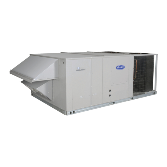
50TC*D
Single Package Rooftop, 50Hz
Cooling Only
with NOVATION™ Coil
Sizes 17, 20, 24, 28 with Puronr (R---410A) Refrigerant
NOTE: Read the entire instruction manual before starting
the installation
TABLE OF CONTENTS
. . . . . . . . . . . . . . . . . . . . . . . . . . . . . . .
. . . . . . . . . . . . . . . . . . . . . . . . . . .
Installation Instructions
. . . . . . . . . . . . . . . . . . . .
. . . . . . . . . . . . . . . . . .
. . . . . .
. . . . . . . . . . . . . . . . . . .
. . . . . . . . . . . . . . .
. . . . . . . . . . . . . . . . . . . .
. .
. . . . . . . . . . . . . . .
.
. . . . . . . . . . .
. . . . . . . .
. . . . . . . . . . . . . . . . . . .
SAFETY CONSIDERATIONS
Improper installation, adjustment, alteration, service,
maintenance, or use can cause explosion, fire, electrical
shock or other conditions which may cause personal
1
injury or property damage. Consult a qualified installer,
service agency, or your distributor or branch for
6
information or assistance. The qualified installer or
6
agency must use factory- - authorized kits or accessories
7
when modifying this product. Refer to the individual
instructions packaged with the kits or accessories when
7
installing.
7
Follow all safety codes. Wear safety glasses and work
10
gloves. Use quenching cloths for brazing operations and
10
have a fire extinguisher available. Read these instructions
11
thoroughly and follow all warnings or cautions attached to
the unit. Consult local building codes for special
11
requirements.
In
12
recommended that the USA standard ANSI/NFPA 70,
13
National Electrical Code (NEC), be followed.
36
It is important to recognize safety information. This is the
36
safety- - alert symbol
unit and in instructions or manuals, be alert to the
potential for personal injury.
Understand the signal words DANGER, WARNING,
CAUTION, and NOTE. These words are used with the
safety- - alert symbol. DANGER identifies the most serious
hazards which will result in severe personal injury or
death. WARNING signifies hazards which could result in
personal injury or death. CAUTION is used to identify
unsafe practices, which may result in minor personal
injury or product and property damage. NOTE is used to
highlight suggestions which will result in enhanced
installation, reliability, or operation.
absence
of
local
codes,
. When you see this symbol on the
it
is
Advertisement
Table of Contents

Related Manuals for Carrier 50TC*D17 Series


Summary of Contents for Carrier 50TC*D17 Series
-
Page 1: Table Of Contents
50TC*D Single Package Rooftop, 50Hz Cooling Only with NOVATION™ Coil Sizes 17, 20, 24, 28 with Puronr (R---410A) Refrigerant Installation Instructions SAFETY CONSIDERATIONS NOTE: Read the entire instruction manual before starting the installation Improper installation, adjustment, alteration, service, TABLE OF CONTENTS maintenance, or use can cause explosion, fire, electrical shock or other conditions which may cause personal SAFETY CONSIDERATIONS... - Page 2 WARNING WARNING PERSONAL INJURY AND ENVIRONMENTAL ELECTRICAL SHOCK HAZARD HAZARD Failure to follow this warning could cause personal Failure to follow this warning could cause personal injury or death. injury or death. Before performing service or maintenance operations Relieve pressure and recover all refrigerant before on unit, always turn off main power switch to unit and system repair or final unit disposal.
- Page 3 C09105 Fig. 1 - - Unit Dimensional Drawing – 17 and 20 Size Units...
- Page 4 C09384 Fig. 1 - - Unit Dimensional Drawing – 17 and 20 Size Unit (cont.)
- Page 5 C09095 Fig. 2 - - Unit Dimensional Drawing – 24 and 28 Size Unit...
-
Page 6: Installation
C09385 Fig. 2 - - Unit Dimensional Drawing – 24 and 28 Size Unit (cont.) INSTALLATION Jobsite Survey 914 mm (36 in) Complete the following checks before installation. 1067 mm (42 in) 1. Consult local building codes or the U.S.A. National Electrical Code (Ref: ANSI/NFPA 70, [American National Standards Institute/National Fire Protection Association], latest revision) for special installation... -
Page 7: Step 2 - Plan For Sequence Of Unit Installation
Table 1 – Operating Weights 50TC*D UNITS KG (LB) Component Base Unit 770 (1697) 777 (1712) 1862 (845) 1991 (903) Economizer 111 (245) 111 (245) 245 (111) 245 (111) Curb 356 mm/14--- in 111 (245) 111 (245) 124 (273) 124 (273) 610 mm/24--- in 143 (315) 143 (315) - Page 8 C09139 Fig. 4 - - Roof Curb Details – 17 and 20 Size Units...
- Page 9 C09140 Fig. 5 - - Roof Curb Details – 24 and 28 Size Units...
-
Page 10: Step 5 - Field Fabricate Ductwork
WARNING PERSONAL INJURY HAZARD Failure to follow this warning could cause personal injury. For vertical supply and return units, tools or parts MAXIMUM ALLOWABLE could drop into ductwork and cause an injury. Install DIFFERENCE MM (IN.) a 90- - degree turn in the return ductwork between the unit and the conditioned space. -
Page 11: Step 7 - Duct Connection, Horizontal Installation
PLACE ALL SEAL STRIP DETAIL A IN PLACE BEFORE PLACING "914-1371" UNIT ON ROOF CURB. (36"-54") "B" SEE DETAIL A DUCT END "C" "A" C09107 DIMENSIONS MAX WEIGHT UNIT 50TC*D17 2035 3249 127.8 1491 58.7 1328 52.3 50TC*D20 2050 3249 127.8 1491 58.7... -
Page 12: Step 9 - - Install External Condensate Trap And Line
Two Position Damper and Economizer Hood Installation 13. Barometric Relief Damper – On units with - - Factory Option barometric relief, remove screws at bottom of relief damper. Do not remove the hinged relief door. 1. Remove hood top from shipping position. (See Check for free swinging movement. -
Page 13: Step 10 - Make Electrical Connections
Units Without Factory- - Installed Disconnect — All units must have an external trap for condensate drainage. Install a trap at least 102 mm (4-in.) deep and When installing units, provide a disconnect switch of protect against freeze-up. If drain line is installed adequate size per local or national wiring code. - Page 14 Fig. 18 - - Typical Low- - Voltage Control Connections or a PremierLink controller (available as factory- - installed option or as field- - installed accessory, for use on a Carrier Unit without thru- - base connection — Comfort Network or as a stand alone control) or the...
- Page 15 Electric Heater Kit Installation Instructions for complete details. Not all available heater modules may be used in every unit. Use only those heater modules that are Carrier approved for use in a specific size unit and duct arrangement (vertical or horizontal). Refer to the label on the unit cabinet for the list of approved heaters.
- Page 16 Low- - Voltage Control Connections — Locate the plug assembly in the electric heater section of the main unit. Connect the plug with the mating low voltage plug located on the heater. CONTL BOARD Plug Assembly Field Connections BRN BRN Elec Htr HR1: Heater contactor, first-stage HR2: Heater contactor, second-stage...
- Page 17 FIOP/accessory EconoMi$ert2 package. SENSOR SUPPLY AIR RETURN AIR The PremierLink controller requires the use of a Carrier electronic thermostat or a CCN connection for time broadcast to initiate its internal timeclock. This is C09059 necessary for broadcast of time of day functions Fig.
- Page 18 C09376 Fig. 26 - - PremierLink Wiring Schematic...
- Page 19 J6-6 factory- - shipped configured for Space Sensor Mode. A Carrier T- - 55 or T- - 56 space sensor must be used. T- - 55 C08212 Fig. 28 - - PremierLink T- - 55 Sensor space temperature sensor provides a signal of space...
- Page 20 LEGEND: --- Space Temperature Sensor FSD --- Fire Shutdown --- Space Temperature Sensor IAQ --- Indoor Air Quality (CO --- Carrier Comfort Network (communication bus) OAQ --- Outdoor Air Quality (CO CMPSAFE --- Compressor Safety RH --- Relative Humidity FILTER...
- Page 21 Connect T- - 56 - - See Fig. 29 for T- - 56 internal If the 50TC*D unit has an economizer system and connections. Install a jumper between SEN and SET free- - cooling operation is required, a sensor representing terminals as illustrated.
- Page 22 The outdoor enthalpy changeover setpoint is set at the enthalpy controller. Differential Enthalpy Control — Differential enthalpy control is provided by sensing and comparing the outside air and return air enthalpy conditions. Install the outdoor air enthalpy control as described on page 21. Add and install a return air enthalpy sensor.
- Page 23 Outdoor Air Quality Sensor (PNO 33ZCSENCO2 plus Connect one side of the switch’s NO contact set to CTB’s weatherproof enclosure) — The outdoor air CO sensor is THERMOSTAT- - R terminal. Connect the other side of the designed to monitor carbon dioxide (CO ) levels in the NO contact set to TB1- - 10.
- Page 24 1000- - ft (305 m) section. Optically isolated RS- - 485 repeaters are required every 1000 ft CCN Bus (305 m). NOTE: Carrier device default is 9600 band. + (RED) J2-1 COMMUNICATION BUS WIRE SPECIFICATIONS —...
- Page 25 RTU- -MP control system The RTU- - MP control is factory- - mounted in the 50TC*D unit’s main control box, to the right of the CTB. See Fig. 44. Factory wiring is completed through harnesses The RTU- - MP controller, see Fig. 43, provides expanded connected to the CTB.
- Page 26 C09377 Fig. 45 - - RTU- - MP System Control Wiring Diagram...
- Page 27 Parallel pins J5--- 1 = J2--- 6, J5--- 3 = J1--- 10, J5--- 5 = J1--- 2 are used for field --- installation. The RTU- - MP controller requires the use of a Carrier Outdoor Air Temperature (OAT) Sensor - - The OAT is space sensor.
- Page 28 BLU (SPT) reconnect the connectors to the board. Space Temperature (SPT) Sensors A field- - supplied Carrier space temperature sensor is required with the RTU- - MP to monitor space temperature. There are 3 sensors available for this application: COM- PWR+...
- Page 29 Indoor Air Quality (CO sensor) — The indoor air quality Outdoor Air Quality Sensor (PNO 33ZCSENCO2 plus sensor accessory monitors space carbon dioxide (CO weatherproof enclosure) — The outdoor air CO sensor is levels. This information is used to monitor IAQ levels. designed to monitor carbon dioxide (CO ) levels in the Several types of sensors are available, for wall mounting...
- Page 30 Remote Occupancy Space Relative Humidity Sensor - - The RH sensor is not used with 50TC*D models at this time. The remote occupancy accessory is a field- - installed Communication Wiring - - Protocols accessory. This accessory overrides the unoccupied mode and puts the unit in occupied mode.
- Page 31 Local Access Virtual BACview Virtual BACview is a freeware computer program that BACview Handheld functions as the BACview Handheld. The USB Link The BACview is a keypad/display interface used to interface (USB- - L) is required to connect a computer to connect to the RTU- - MP to access the control information, the RTU- - MP board.
- Page 32 Table 10 – Unit Wire/MOCP Sizing Data ELECTRIC HEATER POWER SUPPLY DISC. SIZE TYPE Fuse or Part Number Part Number HARC (ea) Side Supply Vertical Supply (kW) Brkr — — — — 41.4 CRHEATER273A00 CRHEATER282A00 25.1 17.4 41.4 — CRHEATER274A00 CRHEATER283A00 50.1 34.7...
- Page 33 Table 10 – Unit Wire/MOCP Sizing Data (cont) ELECTRIC HEATER POWER SUPPLY DISC. SIZE TYPE Fuse or Part Number Part Number HARC (ea) Side Supply Vertical Supply (kW) Brkr — — — — 42.4 CRHEATER273A00 CRHEATER282A00 25.1 17.4 42.4 — CRHEATER274A00 CRHEATER283A00 50.1...
- Page 34 Table 10 – Unit Wire/MOCP Sizing Data (cont) ELECTRIC HEATER POWER SUPPLY DISC. SIZE TYPE Fuse or Part Number Part Number HARC (ea) Side Supply Vertical Supply (kW) Brkr — — — — 48.8 CRHEATER273A00 CRHEATER282A00 25.1 17.4 48.8 — CRHEATER274A00 CRHEATER283A00 50.1...
- Page 35 Table 10 – Unit Wire/MOCP Sizing Data (cont) ELECTRIC HEATER POWER SUPPLY DISC. SIZE TYPE Fuse or Part Number Part Number HARC (ea) Side Supply Vertical Supply (kW) Brkr — — — — 52.7 CRHEATER273A00 CRHEATER282A00 25.1 17.4 52.7 — CRHEATER274A00 CRHEATER283A00 50.1...
-
Page 36: Step 11 - Adjust Factory- -Installed Options
EconoMi$er2 (without control/for external signal and integrated barometric relief) Catalog No: 50TC ---C01SI Copyright 2009 Carrier Corp. D 7310 W. Morris St. D Indianapolis, IN 46231 Printed in U.S.A. Edition Date: 09/09 Manufacturer reserves the right to change, at any time, specifications and designs without notice and without obligations.
Need help?
Do you have a question about the 50TC*D17 Series and is the answer not in the manual?
Questions and answers