Table of Contents
Advertisement
Quick Links
Advertisement
Chapters
Table of Contents

Related Manuals for Simonelli MUSICA


Summary of Contents for Simonelli MUSICA
- Page 1 SERVICE MANUAL...
- Page 2 SErvIcE Manual Edition Date Modifications 12/2015 First Edition Ed. 01 of 12/2015...
- Page 3 SErvIcE Manual MACHINE DESCRIPTION FIRST INSTALLATION AND PRELIMINARY OPERATIONS REMOVAL OF THE EXTERNAL SURFACE INFUSION UNIT HEATER HYDRAULIC CIRCUIT ELECTRIC COMPONENTS TROUBLESHOOTING DIAGRAMS MAINTENANCE CHECKING SPARE PART CATALOGUE Ed. 01 of 12/2015...
-
Page 5: Table Of Contents
SErvIcE Manual InDEX MACHINE DESCRIPTION . . . . . . . . . 1 .1 6. HYDRAULIC CIRCUIT . . . . . . . . . . . . 6 .1 1 .1 DESCRIPTION . - Page 6 SErvIcE Manual Ed. 01 of 12/2015...
-
Page 7: Machine Description
SErvIcE Manual MacHInE DEScrIPTIOn InDEX MACHINE DESCRIPTION . . . . . . . . . 1 .1 1 .1 DESCRIPTION . . . . . . . . . . . . . . . . . . . . . . . 1 .2 1 .2 KEYBOARD DESCRIPTION (Standard configuration) . -
Page 8: Description
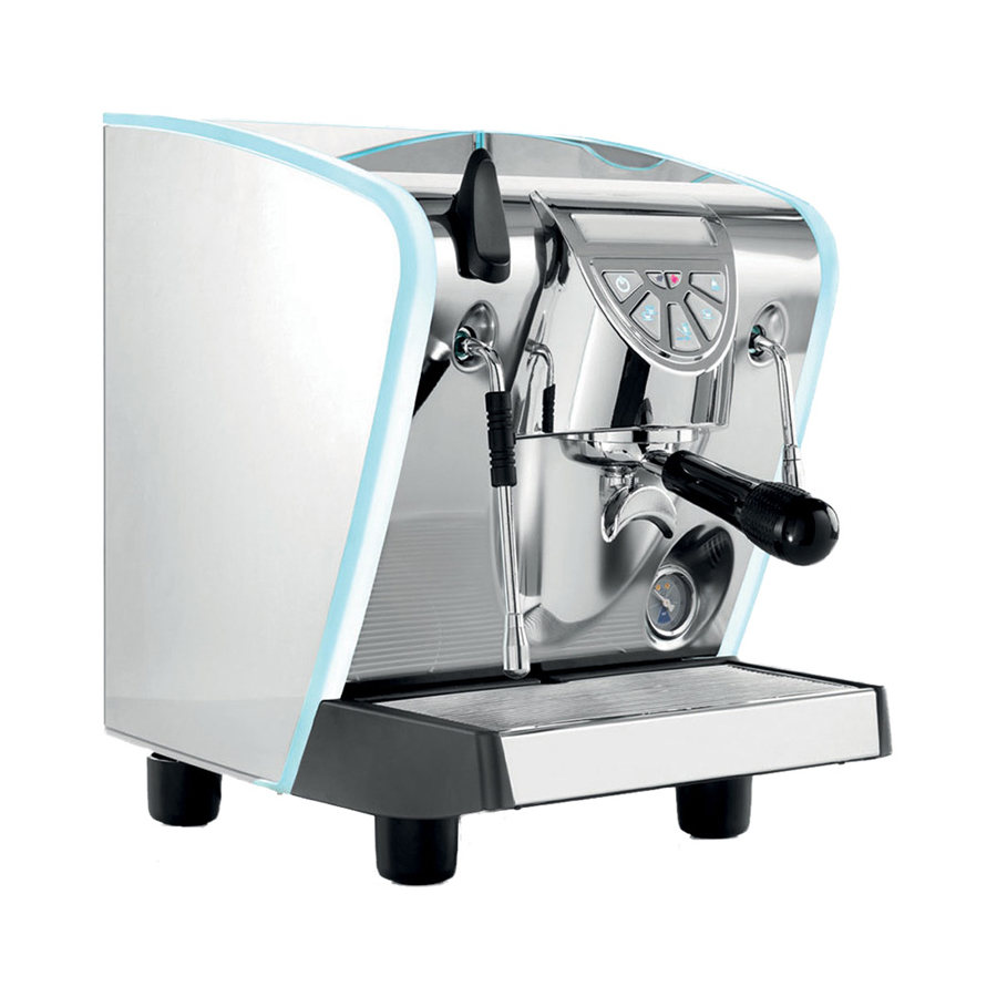
SErvIcE Manual DEScrIPTIOn Fig . 1 lEGEnD Water reservoir Steam knob Control panel Insulating socket Moveable steam nozzle Delivery assembly attachment Water drain tank Cup support grill Pressure gauge 10 Machine power switch 11 Light switch 12 Hot water dispenser wand 13 Cup warming shelf 14 Water reservoir hatch Ed. -
Page 9: Keyboard Description
SErvIcE Manual KEYBOarD DEScrIPTIOn (Standard configuration) Fig . 2 lEGEnD Boiler tank heating element indicator light Machine on/off switch 2 coffee dispensing button Continuous coffee dispensing button 1 coffee dispensing button Hot water dispensing button Water tank indicator light Ed. 01 of 12/2015... -
Page 10: Safety Regulations
SErvIcE Manual SaFETY rEGulaTIOnS Fig . 4 The present manual is an integral and essen- tial part of the product and is to be delivered to the user. Carefully read all warnings in the manual as they provide important information required to install, use and maintain the unit safely. - Page 11 SErvIcE Manual Fig . 6 At the end of installation, the device is switched on and taken to rated operating conditions, leaving it in a state in which it is “ready for operation”. The device is then switched off and the whole hydraulic circuit is bled of the first lot of water in order to remove any initial impurities.
- Page 12 SErvIcE Manual Fig . 8 CAUTION DANGER OF BURNS Fig . 10 The user must never replace the unit's power supply cord. If this cord is damaged, turn off the unit and have it replaced by a profession- ally qualified technician. ...
-
Page 13: Machine Identification
Serial Date of gerous substances in electric and number production electronic equipment, as well as Mod. MUSICA S.N. SERIALE Date 01/01/0001 the disposal of wastes“ . QR code 220 - 240 V ~ P= 1200 W... -
Page 14: Transport
SErvIcE Manual TranSPOrT The machine is transported on pallets which also contain other machines - all boxed and secured to the pallet with supports. Before carrying out any transport or handling operation, the operator must: • put on work gloves and protective footwear, as well as a set of overalls which must be elasticated at the wrists and ankles. -
Page 15: Preliminary Operations
Service Manual FirST inSTallaTiOn anD PreliMinarY OPeraTiOnS inDeX FIRST INSTALLATION AND PRELIMINARY OPERATIONS . . . . . . 2 .1 2 .1 FIRST INSTALLATION . . . . . . . . . . . . . . . . 2 .2 2 .1 .1 WEIGHT AND DIMENSIONS . -
Page 16: First Installation
Service Manual FirST inSTallaTiOn RISK OF POLLUTION 2.1.1 WeiGHT anD DiMenSiOnS DO NOT DISPOSE PACKAGING in the environ- ment . NET WEIGHT 20 kg 44,1 lb Prior to installation please carefully read the GROS WEIGHT 23 kg 50,7 lb safety instructions in this manual. The company cannot be held responsible for damage to per- sons or property arising from non-compliance POWER... -
Page 17: Connection To The Water
Service Manual 2.1.2 cOnnecTiOn TO THe Wa- Terline anD DrainaGe SYSTeM The machine requires stringent specifications to prevent the formation of limescale and to ensure quality beverages. The main features required to achieve high standards of performance are the following: 50 -60 ppm Total hardness WARNING... -
Page 18: Technical Specifications
Service Manual 2.1.3 TecHnical SPeciFicaTiOnS The machine is available in the following ver- sions: • single-phase 120 V 60 Hz (tank and waterline) • single-phase 230 V 50 Hz (tank and waterline) • single-phase 230 V 60 Hz (waterline) The relative power absorbed is indicated on the machine plate. -
Page 19: Procedure Of
Service Manual 2.1.5 PrOceDure OF FirST Fig . 16 inSTallaTiOn Before installing the unit, carefully read the safety instructions at the beginning of this manual. Arrange the accessories as follows: Insert the ring (3) inside the seat of the filter holder. - Page 20 Service Manual Make certain that the cup support grill (8) is posi- tioned squarely and is level. Make sure that the steam knob (2) is closed, facing down. Make certain that the line voltage corre- sponds to the requirements indicated on the label.
-
Page 21: Accessories Box
Service Manual acceSSOrieS BOX Fig . 17 Machine is supplied with an accessories box consisting of: Single filter Double filter Spring Filter holder Dispensing nozzle Coffee doser Coffee presser 2.2.1 FiTTinG THe FilTer HOlDer To properly mount the filter holder: Insert the spring inside the pay slot inside the filter holder. -
Page 22: Coffee Dose Setting
Service Manual cOFFee DOSe SeTTinG Fig . 18 To enter the programming mode, proceed as fol- lows: NOTE The procedure can be carried out with the machine on. • To enter the dose programming mode, it is necessary to press and hold down the con- tinuous dispensing key for 5 sec. - Page 23 Service Manual Hot water dose setting Fig . 20 • Use the relevant procedure to enter the pro- gramming function. • Press the hot water selection key • Hot water delivery will begin. • Decide the required amount of hot water and then press the key again.
- Page 24 Service Manual Additional functions Also within the programming function (while no pouring is in progress), pressing the “ ” key and then holding it down and pressing the “ ”, opens the page for setting the parameters: Software block activation to enter the dose programming mode.
- Page 25 Service Manual reMOval OF THe eXTernal SurFace inDeX TOOLS NEEDED: REMOVAL OF THE EXTERNAL SURFACE . . . . . . . . . . . . . . . . . . . . . . . 3 .1 3 .1 REMOVAL OF WATER TANK .
-
Page 26: Surface
Service Manual CUTTING Fig . 22 DANGER Use gloves to protect against sharp or hot surfaces that you can bump against involun- tarily during operations . SURFACES NOTE Before proceeding with the removal of the panels it is advisable to clean and free up enough space where the machine parts will rest so that they are not be unintentionally damaged . -
Page 27: Removal Of The Cup
Service Manual Pull the water tank upward Fig . 25 reMOval OF THe cup HOlDer SurFace To remove the cup holding surface, proceed as follows: Loosen the screws “A” using a 2,5 mm Allen Fig . 26 key. Raise the panel and take it out backward. Fig . -
Page 28: Removal Of The Side Panels
Service Manual reMOval OF THe SiDe panelS NOTE To remove the side panels, it is necessary to remove the cup holding surface first . Loosen the screws “A” of each panel using a Fig . 28 2,5 mm Allen key. Fig . -
Page 29: Removal Of The Rear Panel
Service Manual Raise the panel and take it out. Fig . 31 reMOval OF THe rear panel NOTE To remove the back panel it is necessary to remove both side panels first . Proceed as follows: Loosen the screws “A” of the panel using a Fig . -
Page 30: Removal Of The Front Panel
Service Manual reMOval OF THe FrOnT panel NOTE To remove the front panel, it is necessary to remove the right side panel first . Loosen the locking nut “A” of steam valve Fig . 34 using a 3 mm Allen key. Release the valve by pulling the steam lever “B”... - Page 31 Service Manual Disconnect keyboard wiring. Fig . 37 Fig . 38 NOTE For LUX version, remove the light transformer before disconnecting the keyboard . Loosen the corresponding screws “E” by means of a phillips screwdriver . Disconnect pipes of the coffee valve “F” and Fig .
-
Page 32: Removal Of Keyboard
Service Manual reMOval OF KeYBOarD NOTE To remove the keyboard, it is necessary to remove the front panel first . Loosen the 4 screws “A” situated on the Fig . 41 back of the front panel using a Phillips screwdriver. Loosen the 4 screws “B”... -
Page 33: Infusion Unit
Service Manual inFuSiOn uniT inDeX TOOLS NEEDED: INFUSION UNIT . . . . . . . . . . . . . . . . . . 4 .1 4 .1 REMOVAL OF SHOWER AND SEAL . -
Page 34: Removal Of Shower
Service Manual The underpan seal prevents water from coming Fig . 43 out from the sides of the pavilion and reach the capsule unevenly or spill from the filter holder. Since the material is plastic and exposed to high temperatures, replace the seal periodically, at least once a year or according to machine opera- tion, as it tends to deform, loosening elasticity and sealing. -
Page 35: Coffee Valve
Service Manual cOFFee valve Fig . 47 It is a solenoid valve that is normally closed and opens when it received a command to dispense coffee. By closing the decompression removes any excess water from the filter holder. TYPICAL PROBLEMS Check the operation of the valve, if the unit con- tinues to drip continuously or if the coffee cap- sule is too wet. - Page 36 Service Manual Remove the washer and the locking nut “B” Fig . 50 using a 14 mm wrench. Remove the coil. Loosen the coil support “C” with a 24 mm Fig . 51 wrench. Use a 3 mm Allen key to remove the two Fig .
-
Page 37: Expansion Valve
Service Manual eXPanSiOn valve To remove the expansion valve, proceed as fol- lows: Fig . 54 Remove the front panel. Disconnect the Teflon tube by removing the cable holder “A” using the pliers. Loosen the valve with a 14 mm wrench. Fig . - Page 38 Service Manual Ed. 01 of 12/2015...
-
Page 39: Heater
SERvIcE MANuAl HEATER INDEX TOOLS NEEDED: HEATER . . . . . . . . . . . . . . . . . . . . . . . . 5 .1 5 .1 EMPTYING THE HEATER . -
Page 40: Emptying The Heater
SERvIcE MANuAl EMPTYING THE HEATER Fig . 57 DANGER Before proceeding with the operations DANGER described in the chapter make sure that the machine is turned off and unplugged from the mains . Discharge any residual pressure pres- ent in the steam heater . WARNING Before carrying out the heater emptying pro- cedure, remove water inlet sources inside the... - Page 41 SERvIcE MANuAl Connect the drain pipe and tilt the machine Fig . 61 on the left side to let the water out of the heater. After drainage of water from the heater, Fig . 62 tighten the drain nut “A” using a 13 mm wrench.
-
Page 42: Removal Of The Heater
SERvIcE MANuAl REMOvAl OF THE HEATER In case of need, to remove the heater, it is neces- sary to discharge pressure. Then, proceed as follows: Remove machine covers: • Rear panel; • Side panels; • Front panel. Empty water heater, as in the previous section. -
Page 43: Heating Element And Heat Protection
The visible parts are: A 167° heat protection. B Electrical connections of heating ele- ment. MUSICA heater features a 1200 W heating ele- ment. To remove the heating element, proceed as fol- lows: Fig . 67 Empty the heater as described above. -
Page 44: Replacement Of The Level Gauge
SERvIcE MANuAl REPlAcEMENT OF THE Fig . 70 lEvEl GAuGE Water inside the heater is kept at a constant level through the use of a level probe. This probe is connected to the electronic unit, which continuously checks water level. Being always exposed to high temperatures and steam/water it is subject to encrustations which can inhibit operations. -
Page 45: Anti-Suction Valve
SERvIcE MANuAl ANTI-SucTION vAlvE Fig . 73 The anti-suction valve ensures that air enters the heater during the machine cooling phase. In this way the reduction of water volume due to cooling does not create decompressions that may give rise to drawbacks such as the suction of milk through the steam nozzle. -
Page 46: Safety Valve
SERvIcE MANuAl SAFETY vAlvE Fig . 75 The heater safety valve “A” of heater serves to discharge excess pressure that may form owing to malfunctioning. The valve opens automatically when inner pressure of heater exceeds 2.1 bar. WHEN TO REPLACE For safety reasons each time the valve comes into operation it should be replaced to ensure perfect operation. -
Page 47: Hydraulic Circuit
Service Manual HYDraulic circuiT inDeX TOOLS NEEDED: HYDRAULIC CIRCUIT . . . . . . . . . . . . 6 .1 6 .1 PUMP DISASSEMBLY . . . . . . . . . . . . . . . . 6 .2 6 .2 REPLACING THE COFFEE VALVE . -
Page 48: Pump Disassembly
Service Manual wARNING Before carrying out the disassembly proce- dure of the hydraulic circuit, close water inlet sources inside the waterline: • Waterline version: close the water inlet tap and disconnect the pipe . • Tank version: remove the tank from its seat . - Page 49 Service Manual Disconnect the hydraulic connections of the Fig . 79 pump: • From the flowmeter, disconnect the Teflon pipe “B”. • From the pump to the heater, unscrew Fig . 80 the fitting “C” using a 13 mm spanner. Disconnect the electrical connections of the Fig .
-
Page 50: Replacing The Coffee Valve
Service Manual rePlacinG THe cOFFee Fig . 82 valve The coffee valve “A” is situated underneath the upper panel, on the left side, and regulates the amount of water flowing inside the heater during all phases of machine operation. wHEN TO INTERVENE The system detects the absence of water and the pump is set off but the pump sounds like it’s straining badly: the valve is stuck. - Page 51 Service Manual Using a 24 mm wrench, remove the fixed Fig . 85 part “C”. Disconnect the hydraulic connections “D” Fig . 86 by using a 12 mm wrench. Loose the locking screws “E” to release the valve from the machine frame. Make sure the plunger is clean and there are Fig .
-
Page 52: Flowmeter
Service Manual FlOwMeTer The issues related to flowmeter are those arising when dosing coffee, therefore only when the pre- set dosage buttons are used. wHEN TO INTERVENE The most common errors that you may encoun- ter are: Wires disconnected accidentally or uninten- tionally (e.g. - Page 53 Service Manual HOw TO CHECK THE FLOwMETER To measure the signal, it is necessary to access the electronic board located on the right side. Remove the right, side panel. With a multimeter measure the voltage alter- Fig . 89 nating between the ends of the faulty dis- penser (see figure).
-
Page 54: Hot Water Valve
Service Manual HOT waTer valve wHEN TO INTERVENE The following problems may occur: Failure to deliver water. Continuous dripping. Erroneous programming. Cases 1 and 2 are due to malfunction of the valves so you need to access them and verify that they are working properly. The valve may stop operating due to electri- cal problems or is not working properly due to obstructions for example caused by pieces of... - Page 55 Service Manual Disconnect power connections using twee- Fig . 95 zers. Remove the inner rear panel (tank hous- Fig . 96 ing) by loosening the 4 screws “A” using a Phillips screwdriver. Remove the locking nut “B” using a 14 mm Fig .
-
Page 56: Of Hot Water Nozzle
Service Manual Check the spring is working properly and Fig . 99 that the inner cylinder is clean. Replace the valve completely, if there is nothing visible that affects its use. Fig . 100 6.4.1 DiSaSSeMBlY OF HOT wa- Ter nOzzle To reassemble the hot water nozzle, proceed as follows: Remove the front panel (see paragraph 3.5). - Page 57 Service Manual If there is a loss of vapor or condensation, it is Fig . 103 necessary to: Turn the machine off, let out all the steam until there is no pressure in the heater. Remove the left side panel and the front one. Fig .
- Page 58 Service Manual DISASSEMBLY OF THE STEAM LEVER Fig . 107 Remove the machine front panel. Unlike the nozzle, the lever is extracted together with the panel. Remove the Seeger ring “A” using the pliers. Remove the piston “B” from the opposite side.
- Page 59 Service Manual Using a 22 mm wrench remove the steam Fig . 111 nozzle from its housing. We recommend replacing the seal at least once a year. Unscrew the fitting "A" with a 21 mm wrench Fig . 112 to reach the spring. We recommend replacing the seal at least once a year.
- Page 60 Service Manual wARNING Operation to be performed when the machine is on . When fixing the screw that holds the lever on the Fig . 115 stream nozzle it is necessary to: Lightly press the lever upwards to let steam come out.
-
Page 61: Water Tank
Service Manual waTer TanK To access the water tank, remove the rear panel. NOTE In case of a prolonged inactivity of the machine, the tank valve may be blocked owing to limescale . To release the tank valve, use a screwdriver to allow water discharge. -
Page 62: Removal Of The
Service Manual 6.6.2 reMOval OF THe MaGneTic SenSOr This sensor serves to detect the presence of water inside the tank. In case of breakdown or malfunctioning, it can be replaced. Take out the water tank from its housing and remove the rear panel. Unscrew the sensor "A"... -
Page 63: Pressure Switch
Service Manual reMOval PreS- Fig . 121 Sure SwiTcH The pressure switch cuts off the circuit powering the heating element. Therefore, it will read a volt- age as the one of mains when heater pressure is enough, while will read 0V when the heating element is warming up. - Page 64 Service Manual 6.18 Ed. 01 of 12/2015...
-
Page 65: Electric Components
Service Manual elecTric cOMPOnenTS inDeX TOOLS NEEDED: ELECTRIC COMPONENTS ..7.1 CONTROL UNIT ..... 7.2 Ed. -
Page 66: Control Unit
Service Manual cOnTrOl uniT Fig. 123 To access the main board it is necessary to: Remove the right, side panel. Disconnect the electrical connections using the pliers. Unscrew the two screws “A” with a Phillips screwdriver and remove the board support with the board inside. -
Page 67: Troubleshooting
SErvIcE MaNual TrOuBlESHOOTING INDEX TROUBLESHOOTING . . . . . . . . . . . . . 8 .1 WATER LACK LIGHT . . . . . . . . . . . . . . . . . 8 .2 HEATING ELEMENT LIGHT . -
Page 68: Water Lack Light
SErvIcE MaNual WaTEr lacK lIGHT Water lack light on. Lack of water in the tank. Fill the tank with drinkable Water in the tank. water. Check the magnetic sen- Float in the tank out of sor. Replace, if necessary. place or faulty. Check float position-... -
Page 69: Heating Element Light
SErvIcE MaNual HEaTING ElEMENT lIGHT Temperature light in oper- Heat protection on (oper- ating mode off (after 30 ating temperature consid- min.). erably exceeded). Check the thermal protection and replace it, if necessary. Check the heating ele- ment conditions. Replace, if necessary. -
Page 70: Removal Of Keyboard
SErvIcE MaNual rEMOval OF KEYBOarD When pressing the keys, Alarm enabled: nothing happens. • Lack of water; the cor- responding light is on. • Machine not ready; operating temperature not reached; the cor- Check connections and Check the keyboard and, responding light is off. -
Page 71: Lights (Lux Versions)
SErvIcE MaNual lIGHTS (luX vErSIONS) Check power connections When pressing the key, of covers. the lights do not go on. Make sure the machine is turned on. Check the light switch. Replace, if necessary. Check connections and electronic board. Replace, if necessary. Ed. -
Page 72: Coffee Delivery
SErvIcE MaNual cOFFEE DElIvErY The pump is operating but The machine does not Check for any problems there is not water in the deliver coffee. due to keyboard. tank. Check the presence of air Check for any problems Check the shower and, if between the tank and the due to heater. -
Page 73: Water Delivery
SErvIcE MaNual WaTEr DElIvErY When pressing the water Check for any problems delivery key, the machine arising from keyboard. does not deliver. Check the water valve and, Check for any problems if necessary, replace it. arising from heater. Ed. 01 of 12/2015... -
Page 74: Steam Delivery
SErvIcE MaNual STEaM DElIvErY When pressing the steam Check for any problem lever, the machine does arising from heater warm- not deliver. ing up. Check the steam nozzle. Remove limescale residue. Replace, if neces- sary. Ed. 01 of 12/2015... -
Page 75: Heater
SErvIcE MaNual HEaTEr With the water tank full, When reaching the oper- Odour from the heater. there is no water in the ating temperature heater. Check the anti-vacuum Check the coffee valve. valve and, if necessary, Replace, if necessary. replace it. Check the tank valve. - Page 76 SErvIcE MaNual 8.10 Ed. 01 of 12/2015...
-
Page 77: Diagrams
Service Manual DiaGraMS HYDraulic DiaGraM TanK verSiOn Ed. 01 of 12/2015... -
Page 78: Direct Connection Version
Service Manual HYDraulic DiaGraM DirecT cOnnecTiOn verSiOn Ed. 01 of 12/2015... -
Page 79: Wiring Diagram Tank Version
Service Manual WirinG DiaGraM TanK verSiOn Ed. 01 of 12/2015... -
Page 80: Wiring Diagram Direct
Service Manual WirinG DiaGraM DirecT cOnnecTiOn verSiOn F=3.15A S.L. S.T. GND. GND. IMP. +12V Ed. 01 of 12/2015... -
Page 81: Maintenance Checking
Service Manual Maintenance checking inDeX Maintenance checking . . . . . . 10 .1 10.1 DaiLY Maintenance . . . . . . . . . . . . . . . 10 .2 WeekLY Maintenance . -
Page 82: Daily Maintenance
Service Manual DailY Maintenance 10.1 Time required 5 min: Clean the machine; Clean the unit with the blind filter and specific detergent (Pulycaff); Empty the water collection tray. WeeklY Maintenance 10.2 Time required 10 min: Clean the machine; ... -
Page 83: Yearly Maintenance
Service Manual YearlY Maintenance 10.3 Time required 45 - 60 min: The skilled technician should take all the necessary precautions concerning safety measures to insu- late the machine from the mains and to avoid pressure in the heater, waterline closure or tank removal so as to prevent inconveniences or damages. -
Page 84: Biennial Maintenance
Service Manual Biennial Maintenance 10.4 Time required 60 - 90 min: The skilled technician should take all the necessary precautions concerning safety measures to insu- late the machine from the mains and to avoid pressure in the heater, waterline closure or tank removal so as to prevent inconveniences or damages. - Page 85 Service Manual annual Maintenance 02280011 98120001 98008004 02280014 02280037 02280020.C 03000066 02280036 03000073 03000072 01000023 09200014 change every 12 months change every 24 months 10.5 Ed. 01 of 12/2015...
- Page 86 Service Manual 10.6 Ed. 01 of 12/2015...
-
Page 87: Spare Part Catalogue
TÔLE FERMETURE CHÂSSIS RACC. DIRECT MUSICA LOCKING PLATE FRAME - MUSICA D.A. 03002383 GRILLAGE EN INOX PLAN TRAV. MUSICA STAINLESS STEEL MESH, WORK SURFACE - MUSICA FICHE A LAMELLE M 6.3 d4.2 45° 04000198 FOIL HOLDER M 6.3 D 4.2 45°... -
Page 88: Cabinet Parts
SErvIcE MaNual 11.1 caBINET ParTS 05000758.GO 980100000000680003 NERO 05000260.GO 980100000000680004 NERO - CSA 980100000000680005 FUXIA 03002362 980100000000680006 FUXIA - CSA 98010000000058 LUX 980100000000700001 NERO 980100000000700002 FUXIA 98010000000060 LUX 05000264.C 31000260 980100000000660003 NERO 03002364 980100000000660004 NERO - CSA 05000242 980100000000660005 FUXIA 980100000000660006 FUXIA - CSA 03002366 98010000000056 LUX... -
Page 89: Complete Pouring Unit
SErvIcE MaNual 11.2 cOMPlETE POurING uNIT 08000003 00300040 98120001 11600002 07300684 (Ø3.2mm) CSA 00000118 73004013 04100038 - 230V 04100037 - 115V 08000003 11600002 07300225 (Ø3mm) CSA 02280020.C 07300183 03000066 00300021 03/2014 00000221 00000217 03000073 03000072 08000017 03000107 05000082 05000842 07300601 05000844 05080035 05000840... -
Page 90: Tank Frame Components
SErvIcE MaNual 11.3 TaNK FraME cOMPONENTS 98200000000020 02280040 04100042 - 230V 04100043 - 115V 07300714 11740001 05000097 07300714 02280041 11740001 03002354 02280018 05000759 00000155 04000664 00300005 00000063 07300254 03002360 09100010 00000167 04200043 05002230 00000054 05002228 11600002 04000199 07300525.1 07300525 12/2013 00000054 09500007 01000159... -
Page 91: Direct Connection Frame
SErvIcE MaNual 11.4 DIrEcT cONNEcTION FraME cOMPONENTS 04100042 - 230V 07300714 04100043 - 115V 11740001 07300714 11740001 03002354 03002382 00300005 00000063 00000054 07300254 04000198 09100010 00000011 00000054 00000011 05002230 00000026 05002228 01000092 04000604 09500007 11740001 11740001 07300201 04100060 - 230V - 50Hz 07300525.1 04100061 - 115V- 60 Hz 07300525 12/2013... -
Page 92: Steam & Hot Water
SErvIcE MaNual 11.5 STEaM & HOT WaTEr valvES ParTS 98030400 00300012 00200011 07300110 02280011 08000005 98008004 07300354 02280014 07300221 07300355 05000266 07300252 08000015 02280037 07300104 08000027 00000118 08000015 07300293 02280004 98030402 07300295 07300022.1 98060020 07300251 05000002 04100042-230V 04100043-115V 02280036 75006038.1 07300251 07300017 07300252... -
Page 93: Boiler Components
SErvIcE MaNual 11.6 BOIlEr cOMPONENTS 980300000000920001 - 230V 980300000000920002 - 115V 98013020 CSA (1.8 bar) 98013021 CE (2.1 bar) 07300227 98030075 05000063 98030400 01000023 07300051 03000202 00300002 07300116 00300002 14100040 - 230V 14100041 - 115V 09000006 07300005.1 01000212 07300005 12/2013 07300364 07300718 07300370... -
Page 94: Electrical Components
CABLAGGIO BASSO VOLTAGGIO ALIMENTAZIONE LUCI - 04000666 LIGHTING WIRING ASSEMBLY - MUSICA MUSICA 04000668 CAVO ALIMENTAZIONE LUCI - MUSICA LIGHTING TRASFORMER WIRING ASSEMBLY - MUSICA 04000670 CAVO DOSATORE VOLUMETRICO-CENTRALINA - MUSICA VOLUMETRIC COUNTER CABLE - MUSICA CAVO DOSATORE VOLUMENTRICO ATT. DIRETTO 04000672 VOLUMETRIC COUNTER CABLE - MUSICA D.A. - Page 95 03002382 LOCKING PLATE FRAME - MUSICA D.A. 03002383 GRILLAGE EN INOX PLAN TRAV. MUSICA STAINLESS STEEL MESH, WORK SURFACE - MUSICA 04000198 FICHE A LAMELLE M 6.3 d4.2 45° FOIL HOLDER M 6.3 D 4.2 45° FICHE A LAMELLE DOUBLE M 6.3 d4.2 45°...
- Page 96 WAND SPRING 09000006 SONDE DE NIVEAU AUTOM. COMP. L=70 AVEC GORGE LEVEL PROBE REPLACE CODE 73003011 09100010 MANOMÈTRE ÉCHELLE 0-2,5BAR 1/8 D.40 BAGUE INOX "MUSICA" P RESSURE GAUGE 0-2.5 BAR 1/8 D.40 STAINLESS STEEL RING 09200006 PRESSOSTAT MACHINE CE/UL PRESSOSTAT "...
- Page 97 LEFT EXTERNAL SIDE PANEL – MUSICA FUXIA 980100000000680005 ENSEMBLE CARROSS. CÔTÉ GCHE MUSICA INOX-FUCHSIA 980100000000680006 ENSEMBLE CARROSS. CÔTÉ GCHE MUSICA INOX-FUCHSIA CSA LEFT EXTERNAL SIDE PANEL – MUSICA FUXIA CSA 980100000000700001 ENSEMBLE CARROSS. ARRIÈRE MUSICA INOX-NOIR REAR PANEL – MUSICA BLACK 980100000000700002 ENSEMBLE CARROSS.
- Page 98 SErvIcE MaNual 11.12 Ed. 01 of 12/2015...
- Page 100 E-mail: n.simonelli@nuovasimonelli.it Nuova Distribution Centre LLC 6940Salashan PKWY BLDG A 98248 Ferdale, WA Ph. +1.360.3662226 Fax +1.3603664015 videoconf. +1.360.3188595 www.nuovasimonelli.it info@nuovasimonelli.com Nuova Simonelli reserves the right of make all modifications deemed to be necessary. Graphics by: TYPE ENGINEERING S.r.l...
Need help?
Do you have a question about the MUSICA and is the answer not in the manual?
Questions and answers