Table of Contents
Advertisement
Quick Links
Operator's manual
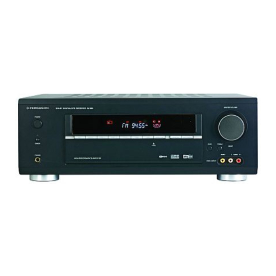
DOLBY DIGITAL/DTS RECEIVER AV-660
POWER
DVD
VIDEO 1
STANDBY
STATION
MEMORY
PHONES
APS
VIDEO 2
VIDEO 3
TUNER
TAPE
AUX
SURROUND
DTS/
TUNING
ST/MONO
BACK
DOLBY DIGITAL
BAND
AV-660
DIRECT IN
DISPLAY
INPUT MODE
BASS
SURROUND MODE
STEREO
DOLBY PL
x
VIDEO 3 INPUT
MASTER VOLUME
TREBLE
RESET
VIDEO
L
AUDIO
R
Advertisement
Table of Contents

Related Manuals for Ferguson AV-660


Summary of Contents for Ferguson AV-660
- Page 1 Operator's manual MASTER VOLUME DOLBY DIGITAL/DTS RECEIVER AV-660 POWER VIDEO 1 VIDEO 2 VIDEO 3 TUNER TAPE DIRECT IN DISPLAY INPUT MODE STANDBY STATION BASS TREBLE SURROUND MODE RESET SURROUND DTS/ TUNING ST/MONO BACK DOLBY DIGITAL STEREO DOLBY PL MEMORY...
-
Page 2: Table Of Contents
CONTENTS Important Safety Instruction………………………………………………………………………………………. 2-3 Before Use……………………………………………………………………………………………………………. .4 Connection………………………………………………………………………………………………………….. 5-9 Antenna Connection……………………………………………………………………………………………… 5 Standard speaker setup for surround sound……………………………………………………………………. 6 Speaker connection……………………………………………………………………………………………….. 7 DVD player, Television (Monitor), etc. connection…………………………………………………………….. 8 Remote control unit……………………………………………………………………………………….………… 9 Front panel information…………………………………………………………………………………………,…. 10 Remote control information………………………………………………………………………………………… 11-12 Rear panel information………………………………………………………………………………………………... -
Page 3: Important Safety Instruction
IMPORTANT SAFETY INSTRUCTION CAUTION: READ THIS BEFORE OPERATING YOUR UNIT. 1. READ AND FOLLOW INSTRUCTIONS---All the safety and operation instructions should be read before the product is operated. Follow all operation instructions. 2. RETAIN INSTRUCTIONS---The safety and operation instructions should be retained for future reference. 3. - Page 4 IMPORTANT SAFETY INSTRUCTION 12. CONTACT THE SERVICE DEPARTMENT SHOULD THE BELOW CONDITIONS EXIST— a. When the power-supply cord or plug is damaged. b. If liquid has been spilled, or objects have fallen into the product. c. If the product has been exposed to rain or water. d.
- Page 5 Keep the set free from moisture. water,and dust. Do not let foreign objects in the set. Avoid high temperatures Allow for sufficient heat dispersion when installed on a rack. Unplug the power cord when not Do not let insecticides,benzene,and using the set for long periods of thinner come in contact with the set.
-
Page 6: Before Use
BEFORE USE READ THIS BEFORE OPERATION BEFORE CONNECTION 1. Choose the installation location of your unit carefully. Caution Avoid placing it in direct sunlight or close to a source Turn off the power of all the equipment before making of heat. Also avoid locations subject to vibration and connections. -
Page 7: Connection
CONNECTION FM INDOOR ANTENNA Crimp the jagged metal fixtures so they hold the braided If you live reasonably close to a transmitter and want to portion using pliers, etc. Put the cover back in place. use the provided lead-type FM antenna, you will have to connect it direct to the “FM 75Ω”... -
Page 8: Standard Speaker Setup For Surround Sound
CONNECTION Standard speaker setup for surround sound 1. TV or Screen 2. Front Left Speaker 3. Subwoofer 4. Center Speaker 5. Front Right Speaker 6. Surround Left Speaker 7. Surround Right Speaker 8. Surround Back Speaker 9. Listening Position Standard speaker setup for surround sound ●... -
Page 9: Speaker Connection
CONNECTION Connecting loudspeakers To avoid damaging the speakers with a sudden high-level signal, be sure to switch the power off before connecting the speakers. Check the impedance of your speakers. Connect speaker with an impedance of 8 ohms or more. The amplifier’s red speaker terminals are the + (positive) terminals and the black terminals are the –... -
Page 10: Dvd Player, Television (Monitor), Etc. Connection
CONNECTION Connecting video components When connecting video components such as DVD Audio connections: players, cable boxes, satellite receivers and television, Some video components are equipped with special digital you can use different types of cables depending on how audio outputs (i.e. DVD players). If your video the video component is equipped. -
Page 11: Remote Control Unit
REMOTE CONTROL UNIT By using the provided remote control unit, the receiver can be controlled from your listening position. BATTERY INSTALLATION To use the remote control unit, point it at the REMOTE SENSOR window of the receiver. Notes: Even if the remote control unit is operated within the effective range, remote control operation may not work if there are any obstacles between the unit and the remote control. -
Page 12: Front Panel Information
FRONT PANEL INFORMATION MASTER VOLUME DOL BY D IGI TAL/D TS AV REC EI VER AV-660 POW ER VIDEO 1 VIDEO 2 VIDEO 3 TUNER TAPE DIRECT IN DISPLAY INPUT MODE STANDBY STATION BASS TREBLE SURROUND MODE SURROUND DTS/ RESET... -
Page 13: Remote Control Information
REMOTE CONTROL INFORMATION BASS TREBLE DELAY STEREO DISPLAY DYNAMIC T. TONE MUTE LFE TRIM SOURCE SEL SELECT SOURCE SEL AUTO/ MANUAL MEMORY ST/MONO BAND TUNING AV-660... -
Page 14: Remote Control Function
REMOTE CONTROL FUNCTION NO. & NAME DESCRIPTION NO. & NAME DESCRIPTION Press this button to turn this unit on or These buttons are used to select a preset POWER Into standby mode. NUMERIC channel during the tuner mode. ON/STANDBY BUTTONS Press this button to choose one of the Tuner frequency up and down. -
Page 15: Rear Panel Information
REAR PANEL INFORMATION DVD-S IN VIDEO 1-S IN VIDEO-S OUT VI DE O 1 VI DE O 2 VI DE O COAX. P / C P / C Manufactured under license from Digital Theater Systems, Inc. ’ U.S. Pat.No s. 5,451,942, 5,956,674, 5,974,380, 5,978,762, DVD IN 6,487,535 and other U.S. -
Page 16: Basic Operation
BASIC OPERATION BASIC OPERATION 1 How to get PL II x: After power on this unit POWER 1. Press the DOLBY PL IIx button on the front panel or on the remote, you will get SURROUND BACK 1 SPEAKER DOLBY PL II x 6 MOVIE (factory default mode), press one of these buttons again, you will get SURROUND BACK 1 SPEAKER DOLBY PL II x 6 MUSIC;... -
Page 17: Radio Operations
BASIC OPERATION K. DTS-ES Matrix 6.1 step. FM: 50 kHz steps; AM: 9 kHz steps This format has the surround back channel matrix encoded and inserted into the left and right surround Two FM modes available: channels so that at playback the output for the left, right, Press ST/MONO button on front panel or remote control and back surround channels are decoded using a to alternate between Stereo mode and Mono mode. -
Page 18: Radio Data System
RADIO DATA SYSTEM d) RT (Radiotext) RADIO DATA SYSTEM (RDS) RDS is a method for the transmission of additional Press “DISPLAY” on the front panel until “RT” appears. information from local Radio Stations. It can only Some Text messages will be shown. operated in FM mode. -
Page 19: Video Operation
VIDEO OPERATIONS Playing Video sources B AN D 1. Select the DVD, VIDEO 1, VIDEO 2 or VIDEO 3 modes by pushing the corresponding button on front panel. 2. Play the component corresponding to the INPUT selected. 3. The picture from the video source can be seen on the TV and the sound from the video source will be heard from the speakers. -
Page 20: Delay Time & Dynamic Range Control
DELAY TIME & DYNAMIC RANGE CONTROL DELAY TIME The delay time can be individually set for the Dolby DYNAMIC RANGE CONTROL Digital/Dolby Pro Logic II modes using the DELAY (CENTER/REAR) buttons. This button controls the compression range of sound track. When you adjust the delay time in the Dolby Digital If the compression is large (DRC = 4/4), the sound effect mode, an additional 15 ms is automatically added to the... -
Page 21: Test Tone, Lfe Trimmer & Channel Select
TEST TONE, LFE TRIMMER AND CHANNEL SELECT. TEST TONE Speaker Level balance Adjustment The test tone function is useful to adjust the relative volume between speakers in DOLBY DIGITAL or DOLBY PRO LOGIC II mode. Once the balance is set, you don’t have to change the LFE TRIM balance as long as the speakers aren’t moved. -
Page 22: Troubleshooting
TROUBLESHOOTING To determine any problem with your receiver, always check the most obvious possible causes first. If any problem still remains after your having checked the items below, consult your nearest dealer. Problem Probable Cause Suggestion Amplifier When listening to the music in stereo. Speakers are connected wrong. -
Page 23: Specifications
SPECIFICATIONS AUDIO SECTION Audio Power Output FRONT (L/R) 100W RMS x 2 (8 ohm, 1% THD) CENTER 100W RMS (8 ohm, 1% THD) SURR. (L/R) 100W RMS x 2 (8 ohm, 1% THD) SURR. BACK 100W RMS (8 ohm, 1% THD) Output Impedance FRONT (L/R) 8 ohm...
Need help?
Do you have a question about the AV-660 and is the answer not in the manual?
Questions and answers