HP MSR1003-8S Installation Manual
Hide thumbs
Also See for MSR1003-8S:
- Command reference manual (471 pages) ,
- Configuration manual (400 pages)

Related Manuals for HP MSR1003-8S


Summary of Contents for HP MSR1003-8S
-
Page 1: Installation Guide
HP MSR1000 Routers Installation Guide Part number: 5998-7749 Document version: 6W102-20150814... - Page 2 The only warranties for HP products and services are set forth in the express warranty statements accompanying such products and services. Nothing herein should be construed as constituting an...
-
Page 3: Table Of Contents
Contents Preparing for installation ············································································································································· 1 Safety recommendations ·················································································································································· 1 Safety symbols ·························································································································································· 1 General safety recommendations ··························································································································· 1 Electricity safety ························································································································································ 1 Examining the installation site ········································································································································· 2 Temperature and humidity ······································································································································· 2 ... - Page 4 Appendix A Chassis views and technical specifications ························································································ 31 Chassis views ································································································································································· 31 MSR1002-4 ··························································································································································· 31 MSR1003-8 ··························································································································································· 32 MSR1003-8S ························································································································································· 32 Technical specifications ················································································································································· 33 Appendix B LEDs ························································································································································ 34 Panel LEDs ······································································································································································· 34 ...
-
Page 5: Preparing For Installation
HP MSR1003-8S Router BJNGA-BB0029 IMPORTANT: For regulatory identification purposes, every MSR1000 router is assigned a regulatory model number (RMN). These regulatory model numbers should not be confused with the marketing name HP MSR100X or the product code. Safety recommendations Safety symbols... -
Page 6: Examining The Installation Site
Correctly connect the interface cables of the router. • • Use an uninterrupted power supply (UPS). Do not work alone when the router has power. • Before installation and replacement, make sure the power has been disconnected. • Examining the installation site The router must be used indoors. -
Page 7: Cooling System
Table 4 Harmful gas limits in the equipment room Max. (mg/m 0.006 0.05 0.01 Cooling system The MSR1000 router adopts left to right airflow for heat dissipation. Figure 1 Airflow through the MSR1000 chassis To ensure good ventilation, the following requirements must be met: Leave at least 10 cm (3.94 in) of clearance at the air inlet and outlet vents. -
Page 8: Emi
Touch only the edges, instead of electronic components when you observe or move a removed • interface module. To attach an ESD wrist strap: Wear the wrist strap on your wrist. Lock the wrist strap tight around your wrist to keep good contact with the skin. Insert the ESD plug into the ESD socket on the chassis. -
Page 9: Installation Accessories
Installation accessories Rubber feet (provided) Cage nut (user supplied) Load-bearing screw (provided) Grounding cable (provided) M6 screw (user supplied) M4 screw (provided) Mounting brackets (provided) Installation checklist Table 5 Installation checklist Item Requirements Result • There is a minimum clearance of 10 cm (3.94 in) around the inlet and outlet air vents for heat dissipation of the router chassis. - Page 10 possible. • Keep the router far away from radio stations, ra and high -frequency devices working in high current. • Use electromagnetic shielding when necessary • The groundi ng cable of the chassis is reliably grounded. • The grounding terminal of the AC power receptacle is reliably grounded.
-
Page 11: Installing The Router
Keep the tamper-proof seal on a mounting screw on the chassis cover intact, and if you want to open the • chassis, contact HP for permission. Otherwise, HP shall not be liable for any consequence. Installation prerequisites You have read "Preparing for installation" carefully. - Page 12 Figure 2 Installation flow Start Rack-mounting Workbench-mounting Determine the installation position Mount the router on a Mount the router in a rack workbench Ground the router Install interface modules Connect interface cables Connect the router to a configuration terminal Connect the power cord Verify the installation Power on the router Troubleshoot the router...
-
Page 13: Installing The Router
Installing the router Mounting the router on a workbench IMPORTANT: Allow 10 cm (3.94 in) of clearance around the chassis for heat dissipation. • Do not place heavy objects on the router. • To mount the router on a workbench: Make sure the workbench is clean, stable, and reliably grounded. - Page 14 Use a mounting bracket to mark the positions of cage nuts on the front rack posts, making sure the cage nuts on the two front rack posts are at the same level. Figure 5 Marking the positions of cage nuts Insert one edge of a cage nut into the hole.
- Page 15 Attach the mounting brackets to the two sides of the chassis and fasten the screws. Figure 7 Attaching the mounting brackets Place the chassis on the rack and use M6 screws to attach the mounting brackets to the rack posts. Figure 8 Securing the router to the rack...
-
Page 16: Grounding The Router
Grounding the router WARNING! Correctly connecting the router grounding cable is crucial to lightning protection and EMI protection. IMPORTANT: The resistance reading should be smaller than 5 ohms between the chassis and the ground. Grounding the router through the rack IMPORTANT: Make sure the rack is reliably grounded before grounding the router. - Page 17 Figure 9 Grounding the router through the rack (1)
-
Page 18: Grounding The Router With A Grounding Strip
Figure 10 Grounding the router through the rack (2) Grounding the router with a grounding strip If a grounding strip is available at the installation site, connect the grounding cable to the grounding strip. Follow the same procedures in "Grounding the router through the rack"... -
Page 19: Grounding The Router With A Grounding Conductor Buried In The Earth Ground
Figure 11 Grounding the router with a grounding strip Grounding the router with a grounding conductor buried in the earth ground If the installation site has no grounding strips, but earth ground is available, hammer a 0.5 m (1.64 ft) or longer angle iron or steel tube into the earth ground to serve as a grounding conductor. -
Page 20: Installing A Dsic
Figure 12 Removing the filler panel Figure 13 Installing the SIC Installing a DSIC CAUTION: DSICs are not hot swappable. Make sure the router is powered off before installing a DSIC. The MSR1002-4 router does not support DSICs. To install a DSIC: Remove the screws on the filler panel on slot 1 and slot 2 of the router to remove the filler panel, as shown in Figure... -
Page 21: Connecting Interface Cables
Connecting interface cables Connect interface cables before powering on the router. This section describes how to connect Ethernet cables. For other cable connection methods, see HP MSR Series Routers Interface Module User Guide. To connect an Ethernet cable: Plug one end of an Ethernet cable into the Ethernet port on the router. -
Page 22: Attaching A Usb Device
Figure 17 Connecting the router to a PC Attaching a USB device CAUTION: Attach only HP-certified USB devices. • To avoid data loss and hardware damage, do not remove a USB device when it is transmitting data. • The USB port does not support hot-swapping of Sierra Wireless's USB modems. -
Page 23: Setting Terminal Parameters
Connect the RJ-45 connector to the console port of the router. Figure 19 Connecting the console cable Setting terminal parameters This section uses a PC with Windows XP as an example. To set terminal parameters: Select Start > All Programs > Accessories > Communications > HyperTerminal. The Connection Description dialog box appears. - Page 24 Figure 21 Setting the serial port used by the HyperTerminal connection Set Bits per second to 9600, Data bits to 8, Parity to None, Stop bits to 1, and Flow control to None, and click OK. To restore the default settings, click Restore Defaults. Figure 22 Setting the serial port parameters Select File >...
- Page 25 Figure 23 HyperTerminal window On the Settings tab, set the emulation to VT100 or Auto detect and click OK. Figure 24 Setting terminal emulation in test Properties dialog box...
-
Page 26: Connecting An Ac Power Cord
Connecting an AC power cord Make sure the router is reliably grounded, and the power switch on the router is in the OFF position. Connect one end of the AC power cord to the AC receptacle on the router, and the other end to the AC power source. -
Page 27: Powering On The Router
System is starting... Press Ctrl+D to access BASIC-BOOTWARE MENU... Booting Normal Extended BootWare The Extended BootWare is self-decompressing..Done. **************************************************************************** HP MSR1003-8S BootWare, Version 2.30 **************************************************************************** Copyright (c) 2010-2015 Hewlett-Packard Development Company, L.P. Compiled Date : Sep 11 2014 CPU ID... - Page 28 Image file flash:/msr100x-cmw710-boot-e030206.bin is self-decompressing..Done. System image is starting... Cryptographic Algorithms Known-Answer Tests are running ... CPU 0 of slot 0 in chassis 0: Starting Known-Answer tests in the user space. Known-answer test for SHA1 passed. Known-answer test for SHA224 passed. Known-answer test for SHA256 passed.
-
Page 29: Examining The Router After Power-On
MSR1003-8 router, see HP MSR Routers Fundamentals Configuration Guide (V5) and HP MSR Routers Fundamentals Command Reference (V5). For information about configuring the MSR1002-4 and MSR1003-8S routers, see HP MSR Routers Fundamentals Configuration Guide (V7) and HP MSR Routers Fundamentals Command Reference (V7). -
Page 30: Replacement Procedure
Replacement procedure CAUTION: SICs and DSICs are not hot swappable. Make sure the router is powered off before replacing a SIC or DSIC. Replacing a SIC Loosen the captive screws on the SIC. Gently pull the SIC out along the slide rails. Install a new SIC. - Page 31 To install filler panels, proceed to steps 3 and 4. Gently push the slot divider into the DSIC slot along the slide rails and tighten the screws. Install the filler panels and tighten the screws. Figure 28 Removing a DSIC Figure 29 Installing the slot divider Figure 30 Installing filler panels...
-
Page 32: Troubleshooting
Keep the tamper-proof seal on a mounting screw on the chassis cover intact, and if you want to open the • chassis, contact HP for permission. Otherwise, HP shall not be liable for any consequence. Power supply failure If the router cannot be powered on and LEDs on the front panel are off, the power supply is faulty. -
Page 33: Garbled Terminal Display
Garbled terminal display If terminal display is garbled, make sure the Data bits field for the console terminal is set to 8. If the Data bits field is set to 5 or 6, the console terminal will display garbled characters. No response from the serial port If the serial port does not respond, verify that the serial cable is in good condition and the serial port settings are correct. -
Page 34: Reset Button Usage Guidelines
Reset button usage guidelines An MSR1000 router provides the Reset button. You can use the button to reboot the system or restore the factory settings. Press the Reset button for a short time to reboot the router. Press the Reset button for more than 4 seconds to reboot the router and restore the factory settings. -
Page 35: Appendix A Chassis Views And Technical Specifications
Appendix A Chassis views and technical specifications Chassis views The following figures are for illustration only. MSR1002-4 Figure 31 Front view (1) Power receptacle (2) Gigabit Ethernet port (GE0) (3) Gigabit Ethernet ports (GE1 to GE4) (4) SFP port (SFP5) (5) Asynchronous/synchronous (6) Console port/AUX port (CON/AUX) serial interface (SERIAL0) -
Page 36: Msr1003-8
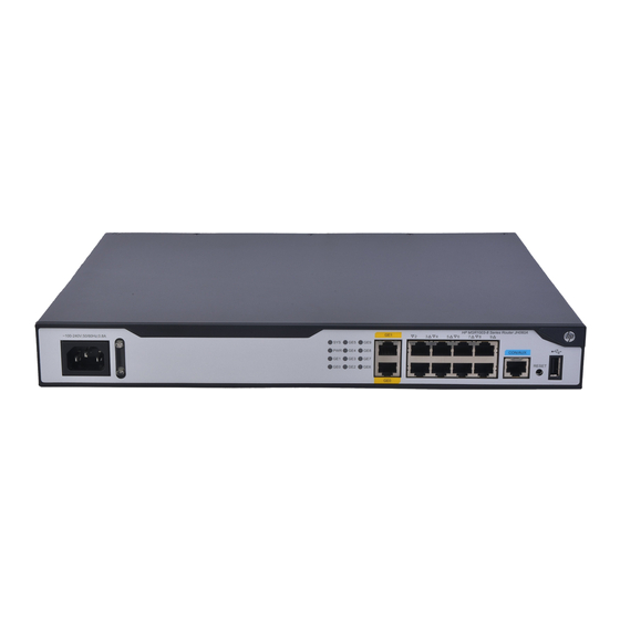
Figure 34 Rear view (1) SIC slot 3 (2) SIC slot 2 (3) SIC slot 1 (4) Grounding terminal MSR1003-8S Figure 35 Front view (1) Power receptacle (2) Gigabit Ethernet port (GE1) (3) Gigabit Ethernet ports (GE2 to GE8) (4) Console port/AUX port... -
Page 37: Technical Specifications
Figure 36 Rear view (1) SIC slot 3 (2) SIC slot 2 (3) SIC slot 1 (4) Grounding terminal Technical specifications Item MSR1002-4 MSR1003-8 MSR1003-8S Console/AUX port USB port Gigabit Ethernet port SFP port Asynchronous/synchr onous serial interface Memory 1 GB DDR3... -
Page 38: Appendix B Leds
Figure 38 MSR1003-8 LEDs (1) System LED (SYS) (2) Power supply LED (PWR) (3) Gigabit Ethernet port LEDs (GE0 to GE9) Figure 39 MSR1003-8S LEDs (1) System LED (SYS) (2) Power supply LED (PWR) (3) Gigabit Ethernet port LEDs (GE0 to GE9) -
Page 39: Led Description
LED description State Description Comware has started with the configuration file and Flashing green (1 Hz) the router has booted up. Flashing green (8 Hz) The BootWare runs. Steady green The SDRAM is performing self-test. Flashing yellow (1 Hz) The DDR3 SDRAM has failed the self-test. Flashing yellow (8 Hz) The extended segment does not exist. -
Page 40: Appendix C Slot Arrangement
The router provides slots for SICs. A DSIC can be installed if you remove the slot divider between two SIC slots. The slot number of fixed ports on the router is 0. Table 6 Slot arrangement on the router Router Slot arrangement MSR1002-4 MSR1003-8 MSR1003-8S : SIC slot : DSIC slot... -
Page 41: Support And Other Resources
Related information Documents To find related documents, browse to the Manuals page of the HP Business Support Center website: http://www.hp.com/support/manuals For related documentation, navigate to the Networking section, and select a networking category. •... -
Page 42: Conventions
Conventions This section describes the conventions used in this documentation set. Command conventions Convention Description Boldface Bold text represents commands and keywords that you enter literally as shown. Italic Italic text represents arguments that you replace with actual values. Square brackets enclose syntax choices (keywords or arguments) that are optional. Braces enclose a set of required syntax choices separated by vertical bars, from which { x | y | ... - Page 43 Network topology icons Represents a generic network device, such as a router, switch, or firewall. Represents a routing-capable device, such as a router or Layer 3 switch. Represents a generic switch, such as a Layer 2 or Layer 3 switch, or a router that supports Layer 2 forwarding and other Layer 2 features.
-
Page 44: Index
"router:connecting to network" XE Grounding the router with a grounding conductor "network:connecting router" , buried in the earth ground XE "hardware:grounding Contacting HP, router with buried grounding conductor" XE "electrical:grounding router with buried grounding Conventions, conductor" XE "procedure:grounding router with Cooling system XE "preparing for installation:cooling... - Page 45 XE "procedure:installing router on Reset button usage guidelines XE "usage workbench" , guidelines:reset button" XE "reset button:usage MSR1002-4, guidelines" XE "troubleshooting:reset button usage MSR1003-8, guidelines" , MSR1003-8S, Restoring the factory settings XE "procedure:restoring factory settings" XE "factory settings:restoring" XE "troubleshooting:restoring factory settings" ,...
- Page 46 specifications:USB console port" XE "technical specifications:USB port" XE "technical Safety recommendations XE "safety:installation specifications:Gigabit Ethernet port" XE "technical recommendations" XE "installing:safety specifications:SIC/DSIC slot" XE "technical recommendations" specifications:memory" XE "technical Safety symbols XE "safety:satefy symbols" XE specifications:CF card memory" XE "technical "installing:safety symbols"...
Need help?
Do you have a question about the MSR1003-8S and is the answer not in the manual?
Questions and answers