Table of Contents
Advertisement
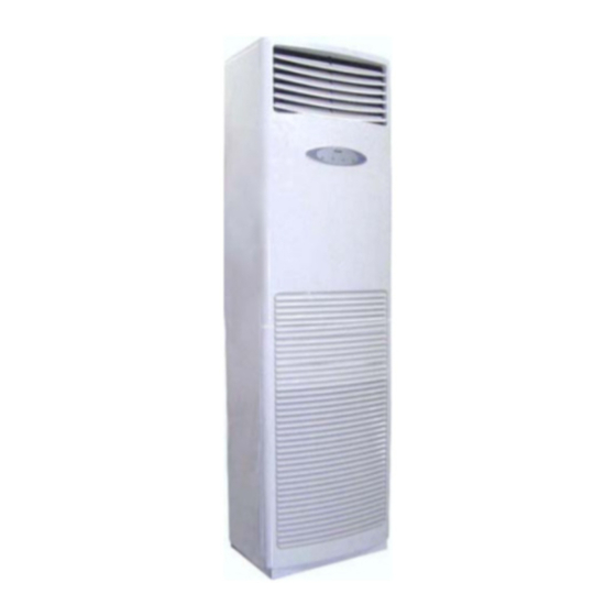
HAIER
Cabinet air conditioner
Technical manual
Machine Model No.:
AP242ACAAA/AU242AHAAA (HPU-24H03)
AP42NACAAA/AU42NAIAAA (HPU-42H03)
AP44NACAAA/AU44NAIAAA (HPU-44H03)
AP42NACABA/AU42NAIABA (HPU-42HB03)
1. Product coding explanation and product series brief instruction
2. Product technical parameter
3. Product specification
4. Name, dimension and function of primary component and accessory
5. Explosion illustration and structure details
6. Usage and setting of remote controller
7. Electric control instruction
8. Diagram circuit
9. Fault diagnosis
10. System flowchart
11. Mounting and maintenance
Contents
Advertisement
Table of Contents

Related Manuals for Haier AP242ACAAA


Summary of Contents for Haier AP242ACAAA
- Page 1 HAIER Cabinet air conditioner Technical manual Machine Model No.: AP242ACAAA/AU242AHAAA (HPU-24H03) AP42NACAAA/AU42NAIAAA (HPU-42H03) AP44NACAAA/AU44NAIAAA (HPU-44H03) AP42NACABA/AU42NAIABA (HPU-42HB03) Contents 1. Product coding explanation and product series brief instruction 2. Product technical parameter 3. Product specification 4. Name, dimension and function of primary component and accessory 5.
- Page 2 Functional code: heating and cooling dual-purpose machine Nominal cooling output (BTU/h) The first two numbers based on thousand unit Structured code of indoor and outdoor unit: Cabinet air conditioner H-Abbreviation of Haier A A A Climatic type: T1 Design serial number...
- Page 3 2. Technical parameter of product Model: Appearance color (internal/external): WHITE HPU-24H03 Outline dimension of indoor unit 1820x530x300mm Outline dimension of outer unit: 948x340x1225mm Packing dimension of indoor unit: 1952x660x417mm Packing dimension of outer unit: 1050x440x1375mm Noise of indoor unit (cooling): upper/lower 50/38dB(A) Noise of outer unit (cooling):...
- Page 4 Model: Appearance color (internal/external): WHITE HPU-42H03 Outline dimension of indoor unit: 1820x530x300mm Outline dimension of outer unit: 948x340x1225mm Packing dimension of indoor unit: 1952x660x417mm Packing dimension of outer unit: 1050x440x1375mm Noise of indoor unit (cooling): upper/lower 50/38dB(A) Noise of outer unit (cooling): upper/lower 58/50 dB(A) Noise of indoor unit (heating): upper/lower...
- Page 5 Model: Appearance color (internal/external): WHITE HPU-42HB03 Outline dimension of indoor unit: 1820x530x300mm Outline dimension of outer unit: 948x340x1225mm Packing dimension of indoor unit: 1952x660x417mm Packing dimension of outer unit: 1050x440x1375mm Noise of indoor unit (cooling): 52/46/40dB(A) Noise of outer unit (cooling): upper/lower 58/50 dB(A) Noise of indoor unit (heating): 50/44/38dB(A)
- Page 6 Model: Appearance color (internal/external): WHITE HPU-44H03 Outline dimension of indoor unit: 1820x530x310mm Outline dimension of outer unit: 1225x960x380mm Packing dimension of indoor unit: 1952x660x455mm Packing dimension of outer unit: 1370x1080x440mm Noise of indoor unit (cooling): 52/46/40dB(A) Noise of outer unit (cooling): upper/lower 58/50 dB(A) Noise of indoor unit (heating): 50/44/38dB(A)
- Page 7 (ZR3K4-PFJ-552) 50000 37.9 40000 48.9 60.0 30000 20000 (BTU) (CRNQ-0500-TFD) 100000 37.9 80000 48.9 60.0 60000 40000 (BTU)
- Page 8 3. Product specification Specification form of split air conditioner: Picture of product 1 Picture of product 2 Model of product AP242ACAAA/AU242AHAAA AP42NACAAA/AC42NAIAAA Structural characteristic Split type Split type Cooling capacity 24000BTU/h 42000BTH/h Voltage 220V 380V Series of product Cabinet type...
-
Page 9: Indoor Unit
Parts HPU-24H03 Indoor unit Outlet grill Operation panel Inlet grill Air filter Remote-controller TEMP SWING MODE SLEEP CLOCK TIMER LOCK RESET Outdoor unit Air inlet [ At side and rear] Compressor [Inside the unit ] Air outlet Piping and electric wire Drain pipe... -
Page 10: Air Outlet
HPU-42H03 HPU-44H03 HPU-42HB03 Indoor unit AUTO TEMP SWING MODE SLEEP CLOCK TIMER LOCK RESET TIMER TIME TEMP MODE TIME ROOM TEMP CLOCK TEMP LOW MID HIGH SLEEP SWING FAN SPEED Outdoor unit Remote-controller Outlet grill Operation panel Air inlet Inlet grill [At side and rear] Air filter[Inside the unit] Air outlet... -
Page 12: Parts List
Parts list the proportion Spare parts Spare parts description Failure of the spare- number in english Qty. Model Price list rate Remark part stock 1 001A1236028 Front grille 0.00% 0.000% × HPU-24H03 2 001A1436160 handle 0.00% 0.000% × HPU-24H03 3 001A0100261 Front panel 0.00% 0.000% ×... - Page 13 41 001A4400511 wire assy. 0.00% 0.000% × HPU-24H03 1,The failer rate and the proportion of the spare-part stock are regarded as the reference of the stock for spare-parts;The first time should be stocked accroded with the proportion of the spare-parts,and it should be adjusted with the actual quantity 3 months later.
- Page 15 Bristol Compressor Detailed statement of explosion figure Model No. AP42NACAAA/AU42NAIAAA outdo r unit Specific Single Name Weight of material Type of material number consumption 5002108 Screw Stainless steel 1236028 Front guard web Weather resisting PP Screw 5002005 Nick treatment Left front panel 1301640 Electro-zinced plate 6040...
- Page 16 Parts list the proportion Spare parts Spare parts description Failure of the spare- number in english Qty. Model Price list rate Remark part stock 001A5002108 Screw 0.00% 0.000% × HPU-42HB03 001A1236028 Front guard web 0.00% 0.000% × HPU-42HB03 001A5002005 Screw 0.00% 0.000% ×...
- Page 17 43 001A1436160 Handle 0.00% 0.000% × HPU-42HB03 1,The failer rate and the proportion of the spare-part stock are regarded as the reference of the stock for spare-parts;The first time should be stocked accroded with the proportion of the spare-parts,and it should be adjusted with the actual quantity 3 months later.
- Page 18 Parts list the proportion Spare parts Spare parts description Failure of the spare- number in english Qty. Model Price list rate Remark part stock 1 001A5002108 Screw 0.00% 0.000% × HPU-44H03 2 001A1236028 Front guard web 0.00% 0.000% × HPU-44H03 3 001A5002005 Screw 0.00%...
- Page 19 43 001A1436160 Handle 0.00% 0.000% × HPU-44H03 1,The failer rate and the proportion of the spare-part stock are regarded as the reference of the stock for spare-parts;The first time should be stocked accroded with the proportion of the spare-parts,and it should be adjusted with the actual quantity 3 months later.
- Page 21 Parts list Spare parts the proportion Spare parts description in Failure of the spare- number english Qty. Model Price list rate Remark part stock 001A1231233 Inlet grill 0.00% 0.000% × HPU-24H03 001A1301502 Inlet grill insert 0.00% 0.000% × HPU-24H03 001A0100384 Front panel 0.00% 0.000% ×...
- Page 22 38 0010200026 Air ring 0.00% 0.000% × HPU-24H03 39 001A0100385 Down shell 0.00% 0.000% × HPU-24H03 40 001A2400102 Filter 0.00% 0.000% × HPU-24H03 41 001A0100075 Door lock 0.00% 0.000% × HPU-24H03 42 001A1734967 Sealing plate 0.00% 0.000% × HPU-24H03 43 001A17621241 Sealing plate 0.00% 0.000% ×...
- Page 23 Parts list proportion of Spare parts Spare parts description Failure the spare- number in english Qty. Model Price list rate Remark part stock 1 001A1231233 Inlet grill 0.00% 0.000% × HPU-42HB03 2 001A1301502 Inlet grill insert 0.00% 0.000% × HPU-42HB03 3 001A0100384 Front panel 0.00%...
- Page 24 40 001A2400102 Filter 0.00% 0.000% × HPU-42HB03 41 001A0100075 Door lock 0.00% 0.000% × HPU-42HB03 42 001A1734967 Sealing plate 0.00% 0.000% × HPU-42HB03 43 001A17621241 Sealing plate 0.00% 0.000% × HPU-42HB03 44 001A1757833 Cushion rubber 0.00% 0.000% × HPU-42HB03 45 001A3000016A Synchro-motor 0.02% 0.024% HPU-42HB03...
- Page 25 Parts list proportion of Spare parts Spare parts Failure the spare- number description in english Model Price list rate Remark part stock 1 001A1231233 Inlet grill 0.00% 0.000% × HPU-44H03 2 001A1301502 Inlet grill insert 0.00% 0.000% × HPU-44H03 3 001A0100384 Front panel 0.00% 0.000%...
- Page 26 38 0010200026 Air ring 0.00% 0.000% × HPU-44H03 39 001A0100385 Down shell 0.00% 0.000% × HPU-44H03 40 001A2400102 Filter 0.00% 0.000% × HPU-44H03 41 001A0100075 Door lock 0.00% 0.000% × HPU-44H03 42 001A1734967 Sealing plate 0.00% 0.000% × HPU-44H03 43 001A17621241 Sealing plate 0.00% 0.000% ×...
- Page 27 Remote controlled operation HEAT COOL OPERATION TEMP Power ON/OFF Used to select your Used for unit desired temp. start and stop. SIGNAL AUTO SENDING AUTO AUTO SWING SWING Used to select fan FAN SPEED Used to set auto speed: LOW,MID, TEMP HIGH,AUTO.
-
Page 28: Operation
Operation Clock set TIMER TEMP MODE TIME TIME TEMP CLOCK When unit is started for the first time SWING FAN SPEED SLEEP and after replacing batteries in remote controller, clock should be adjusted as follows: Press CLOCK button,"AM"or "PM"flashes. Press to set correct time. -
Page 29: Manual Operation
Operation Auto Manual Operation TIMER MODE TEMP TIME TIME TEMP CLOCK ROOM TEMP LOW MID HIGH SWING FAN SPEED SLEEP Remote-controlled Operation Press ON/OFF button Unit starts running. The previous status appears on the display (except. TIMER, SLEEP and SWING mode) AUTO Press MODE button. - Page 30 Cooling Operation Manual Operation SET TEMP TIMER MODE TEMP TIME TIME TEMP CLOCK LOW MID HIGH SWING FAN SPEED SLEEP Remote-controlled Operation Press ON/OFF button Unit starts running. The previous status appears on the display (except. TIMER, SLEEP and SWING mode) Press MODE button.
- Page 31 Operation Manual Operation TIMER MODE TEMP TEMP TIME TIME TEMP CLOCK SWING FAN SPEED SLEEP Remote-controlled Operation Press ON/OFF button Unit starts running. The previous status appears on the display (except. TIMER, SLEEP and SWING mode) Press MODE button. For each press, operation mode changes as follows: Manual AUTO...
- Page 32 Heating Operation Note:For cooling only type, this function is invalid. Manual Operation TIMER TEMP MODE TEMP TIME TIME TEMP CLOCK SWING FAN SPEED SLEEP Remote-controlled Operation Press ON/OFF button Unit starts running. The previous status appears on the display (except. TIMER, SLEEP and SWING mode) Press MODE button.
- Page 33 Operation Manual Operation TIMER MODE TEMP TIME TIME TEMP ROOM CLOCK TEMP SWING FAN SPEED SLEEP Remote-controlled Operation Press ON/OFF button Unit starts running. The previous status appears on the display (except. TIMER, SLEEP and SWING mode) Press MODE button. For each press, operation mode changes as follows: Manual AUTO...
- Page 34 Operation Sleep TIMER MODE TEMP TEMP TIME TIME TEMP CLOCK LOW MID HIGH SWING FAN SPEED SLEEP Remote-controlled operation Before sleeping you can press the Sleep button. The conditioner will run under comfort sleep mode, and give The Sleep running starts The Sleep running stops you a comfort sleep.
-
Page 35: Timer On/Off
Operation Timer on/off operation Manual Operation TIMER MODE TEMP TIME TIMER ON TIME ROOM TEMP CLOCK TEMP LOW MID HIGH SWING FAN SPEED SLEEP Remote controlled operation TIMER operation Set Clock correctly before starting Timer operation(refer to page 3) You can let unit start or stop automatically at following times: Before you wake up in the morning, or get back from outside or after you fall asleep at night. - Page 36 Timer on-off operation Operation Manual Operation TIMER MODE TEMP TIME TIMER ON TIME TEMP ROOM CLOCK TEMP LOW MID HIGH TIMER OFF SWING FAN SPEED SLEEP Remote controlled operation TIMER ON-OFF (1) After unit start,select your desired operation mode. Operation mode will be displayed on LCD. (2)TIMER mode selection Press TIMER button to change TIMER mode.
-
Page 37: Air Flow Adjustment
Air flow adjustment Operation Swing louvers Horizontal louvers (Vertical louvers) (Adjust by hand) Up and down Adjust the louvers by hand to proper position. Note: Put louvers at up position in cooling and down position in heating mode. This will be helpful to keep an even room temp. Notice: In cooling or dry operation, don't put horizontal louvers at downward position for a long time, or outlet grill might get frosted. - Page 38 7. Electric controllable function instruction Describe serial air conditioner model and electric controllable function. (Note: Outdoor fan motor of cabinet air conditioner 5P is single speed) 7.1 Brief instruction of electric controllable function (1) Automatic running (Applies to cooling and heating model) After starting the machine, system changes over automatic mode.
- Page 39 (4) Warm start (avoid of cool air at the beginning of heating , applies to cooling and heating model ) At the just beginning of heating, indoor fan motor will delivery air as follows: if indoor coiled temperature 28 ,start low fan speed; if indoor coiled temperature or operation of compressor 4 minutes,...
- Page 40 (7) Auxiliary electric heater control Auxiliary electric heater starts work on condition that the following conditions are met simultaneously (Tr is room temperature, St is setting temperature in the following selectable conditions): a. Tr 23 b. Tr St-2 Note: after starting electric heater, fan motor won't run at low speed. In case that one of the following conditions is met ,close auxiliary electric heater: a.
- Page 41 Through the medium of prepared interface on main panel , air conditioner is connected with remote controlled detector (made by Haier ) by a two-core line and through the medium of remote controlled detector air conditioner executes command issued by computer or centralized-control unit, at the same time transmit it's current running state and failure information to remote controlled detector.
- Page 42 7.2 Element layout and main element parameter list of printed-wiring board Element layout of indoor printed-wiring board...
- Page 43 Element layout of outdoor printed-wiring board CN10 0057...
- Page 44 Main element parameter list of indoor printed-wiring board Name Element model No. Unit Quantity Label Remarks Power RJ17-6.8K- 5% Philipe resistor Power RJ17-100K- 5% Philipe resistor Capacity Cis-0.1K-250V C8,C9 Ceramic 4MHZ Mulata resonator Optical Toshiba IC3, IC6 TLP521-1 coupler Optical Toshiba TLP371 coupler...
- Page 47 9. Fault diagnosis In the case of abnormal conditions, fault analysis shall be conducted referencing to the following table: Fault coding Fault cause Resolution Remarks 1. Indoor ambient temperature sensor Replace indoor ambient get out of order, short circuit or temperature sensor of computer shutdown plate...
- Page 48 (1) Usage of refrigerant Take fleon R22 as refrigerant, factory filling quantity is 3520g. If the length of connecting line is less than or equal to 5m, additional refrigerant is unnecessary. If the length of connecting line is more than 5m, 50g refrigerant shall be added for every 1 m more.
- Page 49 (1) Usage of refrigerant Take fleon R22 as refrigerant, factory filling quantity is 2380g. If the length of connecting line is less than or equal to 5m, additional refrigerant is unnecessary. If the length of connecting line is more than 5m, 50g refrigerant shall be added for every 1 m more.
-
Page 50: Indoor & Outdoor Unit Connection
Indoor & outdoor unit connection power cable length Approx Approx 1.5m pipe direction Left Rear Right Bottom... -
Page 51: Tools Necessary
Tools necessary Tools necessary 1. Screw driver 2. Hacksaw Parts in the following list are accessories for 3. 70mm dia. hole core drill the unit installation which can be used if necessary. 4. Spanner (dia.17,27mm) 5. Spanner (14,17,27mm) Shape and description 6. -
Page 52: Installation Procedures
Installation procedures Display of whole unit Try to bring the packed unit to the installation place. When it is inevitable to unpack the unit, be careful not to damage the unit. Wrap it with nylon etc. After unpacking, be sure to put it with the front side of the unit facing up. Delivery Facing up Note: When delivering, don't hold plastic parts like inlet and outlet grill etc. -
Page 53: Installation Of Indoor Unit
Installation procedures Installation of indoor unit Selection of installation place Place where it is easy to route drainage pipe and outdoor piping. Place away from heat source and with less direct sunlight. Place where cool and warm air could be delivered evenly to every corner of the room. Place near power supply socket.Leave enough space around the unit (refer to installation drawings). - Page 54 Installation of fall-prevention fitting metal: Fix the fitting metal to the wall by screws so that there is no clearance between them. With the unit set up vertically, fix the fitting metal to the unit with screws while making an adjustment at the long portion of the hole so that there is no clearance between the upper surface and the fitting metal.
- Page 55 2. Piping connection of indoor unit Arrangement of piping and drainage pipe After opening inlet grill, you will see a control box as shown in the Fig. Remove the cover before working. Cut away, with a hammer or a saw, the lid for piping according to piping direction. Insulation material Drain hose Connecting electric cable...
- Page 56 3. Piping connection of outdoor unit. Connect the connecting pipe and inlet and outlet liquid pipe according to the piping method. Purging method Purge air out of indoor unit and piping as shown in the Fig. (1) Remove the valve cap on 2-way valve in outdoor unit. (2) Loosen by 1-1.5 turn the flare nut of gas pipe, which is connected to 3-way valve.
-
Page 57: Electric Wiring
Electric wiring Note: Electric wiring must be done by qualified person. Use copper wire only, the parameter of connecting cable is H07RN-F4 0.75mm . Wiring of indoor unit Insert the cable from outside the wall hole where piping already exist. Pull it out from front. - Page 58 Others 1. Power supply Air conditioner must use an exclusive line (over 30A) When installation air conditioner in a wet place, try to use a circuit breaker against Current leakage. For installation in other places, use circuit breaker as far as possible. 2.
- Page 59 3.Piping connection of outdoor unit. Connect the connecting pipe and inlet and outlet liquid pipe according to the piping Method. Purging method Discharge the air out of the indoor unit and the refrigerant pipe by vacuumizing. (1) Fasten all the nuts of the indoor and outdoor pipes to make these parts out of leakage. (2) Under the condition of the complete close of the indoor and outdoor valve center(both liquid and gas side), dismount the repair valve cap.
- Page 60 Wiring of indoor unit Insert the cable from outside the wall hole where piping already exist. Pull it out from front. Loosen terminal screws and insert cable end fully into terminal block, then tighten it. Pull the cable gently to make sure it is tight. Replace cover after wiring.
Need help?
Do you have a question about the AP242ACAAA and is the answer not in the manual?
Questions and answers