Advertisement
Quick Links
Contents
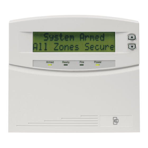
Product summary
The NX-148E-RF Touchpad with Receiver combines touchpad
and receiver capabilities into a single device for use with all
NetworX control panels except CF (commercial fire) panels.
Note:
When using this touchpad with an NX-8E, NX-8V2, NX-6V2,
or NX-4V2 and downloading via modem, make sure the
control panel version is equal to or greater than the
following versions:
• NX-8E
17.00
• NX-8V2
1.04
• NX-6V2
1.05
• NX-4V2
1.04
Make sure you are using DL900 version 2.11 or greater software.
Installation guidelines
Use the following installation guidelines:
• Mount transmitters as close as possible to the touchpad. For
best results, we recommend the distance between the trans-
mitter and the touchpad be less than 100 ft. (30.5 m).
• Mount the touchpads in an environmentally controlled area
with a temperature range from 32 to 120°F (0° to 49°C).
• When mounting the touchpad, allow at least 3 in. (7.6 cm)
below the touchpad for the swing-down door (Figure 1).
Figure 1. Side view
Touchpad
Swing-down door
Mounting-plate screw
• Use Table 1 on page 2 to determine the maximum wire
lengths allowed between the touchpad and the panel.
Tools and supplies needed
• Pencil
• Phillips screwdriver
• Drill
• 15/64 in. drill bit
• Mounting screws (provided)
• Wall anchors (optional)
• 4-conductor, 22, 18, 16, 14 or 12-gauge wire (see Table 1 on
page 2)
NX-148E-RF LCD Touchpad with Receiver
Installation Instructions
1
1
2
5
8
14
14
5 in. (12.7 cm)
3 in. (7.6 cm)
Installation
To install the touchpad, do the following:
1.
Remove the mounting-plate screw (Figure 1) from the
bottom of the touchpad and lift off the mounting plate.
CAUTION:
You must be free of static electricity
before handling circuit boards. Wear a
grounding strap or touch a bare metal
surface to discharge static electricity.
2.
At the mounting location, use the mounting plate to mark
the location for the antenna and mounting holes (Figure 2).
Figure 2. Antenna and mounting holes
Antenna
hole
Mounting holes
Mounting holes
3.
Drill 15/64 in. holes at the marked antenna hole locations.
WARNING:
Make sure the mounting location is
free of electrical wires. Contact with
electrical wires while drilling the
antenna openings could result in
serious injury or death.
4.
Mount the mounting plate to the wall with the screws
provided. Use wall anchors if needed.
5.
Remove power (if applied) from the control panel.
WARNING:
To avoid possible equipment damage
or personal injury, remove power from
the control panel before making any
wiring connections to the module.
466-2198D • November 2009
Copyright © 2009, GE Security Inc.
Antenna
hole
Advertisement

Related Manuals for GE NX-148E-RF


Summary of Contents for GE NX-148E-RF
-
Page 1: Table Of Contents
Product summary surface to discharge static electricity. The NX-148E-RF Touchpad with Receiver combines touchpad and receiver capabilities into a single device for use with all NetworX control panels except CF (commercial fire) panels. -
Page 2: Transmitter Programming
NX-148E-RF LCD Touchpad with Receiver Installation Instructions Transmitter programming Use 22-gauge or larger wire to connect the data, common, and positive terminals on the touchpad (Figure 3) to the This section describes how to program the wireless transmitters data, common, and power terminals on the control panel. - Page 3 Set touchpad number and partition (94) Trip the desired transmitter (within 250 seconds) as described in Table 3. Listen for the ding dong for confirmation. To set the touchpad number and partition, do the following: Enter * 94. Table 3. Tripping transmitters Enter your program code.
- Page 4 NX-148E-RF LCD Touchpad with Receiver Installation Instructions Transmitter options Enter the new normal supervision time (0 to 255) and press *. If you enter 0, it will set the normal supervision time to Door/window transmitter settings 256 hours. To set features 4 (Input option 1) and 5 (Input option 2) for door/...
-
Page 5: Touchpad Programming
Touchpad programming Adjust touchpad tone (0) To raise or lower the tone on the touchpad, do the following: To program the touchpad, do the following: Enter * 0. Press * and enter the function number to select the desired function. Table 4 lists the programming information for Press to raise or lower the tone. - Page 6 NX-148E-RF LCD Touchpad with Receiver Installation Instructions Light control for X10 (46) Assign user authority (6) To control up to ten X10 devices from each touchpad (when used To assign user authority levels, you must have authority over the with an X10 device such as an NX-507E, NX-508E, NX-534E or the assigned partitions.
- Page 7 Program custom messages (92) Set touchpad options (93) When you program custom messages: To set touchpad options, do the following: • If an NX-148 (non-E) is installed on the same system, it Press * 93. must be used to program the text. All messages are trans- Enter your program code.
-
Page 8: Reference Tables
NX-148E-RF LCD Touchpad with Receiver Installation Instructions Reference tables Call back for download (98) To cause the control to do a call back for download (while the system is disarmed), enter * 98. Table 9. Service menu messages Seize phone line for download (99) - Page 9 Table 10. Log messages (continued) Display Description Table 10. Log messages Walk-test A zone Walk Test mode has been activated. Display Description End Test Test has ended. TXlobat Transmitter low battery Cross-Trip The first zone of a cross zone has been tripped (log ZN Lost Zone lost - A wireless multiplexed zone device is not event only).
- Page 10 NX-148E-RF LCD Touchpad with Receiver Installation Instructions Table 11. Module programming settings (continued) Location Segment 1 Segment 2 Table 11. Module programming settings Zone _____ 1 - Enable sensor Partition 1 keyfob Location Segment 1 Segment 2 2 - Supervised...
- Page 11 Table 11. Module programming settings (continued) Table 11. Module programming settings (continued) Location Segment 1 Segment 2 Location Segment 1 Segment 2 Zone _____ 1 - Enable sensor Partition 1 keyfob Zone _____ 1 - Enable sensor Partition 1 keyfob 2 - Supervised Partition 2 keyfob 2 - Supervised...
- Page 12 NX-148E-RF LCD Touchpad with Receiver Installation Instructions Table 11. Module programming settings (continued) Table 11. Module programming settings (continued) Location Segment 1 Segment 2 Location Segment 1 Segment 2 Zone _____ 1 - Enable sensor Partition 1 keyfob Zone _____...
- Page 13 Table 11. Module programming settings (continued) Table 11. Module programming settings (continued) Location Segment 1 Segment 2 Location Segment 1 Segment 2 Zone _____ 1 - Enable sensor Partition 1 keyfob 1 - Enable jam None Receiver Options (all detect 2 - Supervised Partition 2 keyfob defaults off)
-
Page 14: Specifications
NX-148E-RF LCD Touchpad with Receiver Installation Instructions Specifications FCC compliance This device complies with Part 15 of FCC Rules. Operation is subject to Panel Compatibility compatible with all NetworX control panels except CF the following conditions: (commercial fire) panels Frequency 319.5 MHz...
Need help?
Do you have a question about the NX-148E-RF and is the answer not in the manual?
Questions and answers