GE NX-148E - Security NetworX LCD Keypad User Manual
Networx series commercial fire lcd keypad
Hide thumbs
Also See for NX-148E - Security NetworX LCD Keypad:
- User manual (30 pages) ,
- Installation and setup (24 pages) ,
- Installation and setup manual (24 pages)
Table of Contents
Advertisement
Advertisement
Table of Contents

Related Manuals for GE NX-148E - Security NetworX LCD Keypad


Summary of Contents for GE NX-148E - Security NetworX LCD Keypad
- Page 1 ™ NetworX Series NX-148E-CF Commercial Fire LCD Keypad User manual...
- Page 3 Installing/Service Company For Service Call Central Station is not partitioned. This system EMERGENCY ACTIVATION KEYS (check if enabled) Fire Auxiliary Emergency Police PROGRAMMED FUNCTIONS Abort Delay (s) Group Bypass (s) Battery Test Quick Arm (s) Cancel Alarm Re Exit Chime Siren Test Forced Arming (s) (s) These features should not be enabled on UL listed systems.
-
Page 5: Table Of Contents
TABLE OF CONTENTS GLOSSARY OF TERMS................4 UNDERSTANDING THE LIGHTS............. 6 KEYPAD FUNCTIONS................7 Arming Your System In The “Away” Mode........... 7 Making Your System Ready To Arm............ 7 Arming Your System In The “Stay” Mode ..........8 Using The Quick Arm ................9 Disarming Your System ............... - Page 6 THIS MANUAL IS FURNISHED TO HELP YOU UNDERSTAND YOUR SECURITY SYSTEM AND BECOME PROFICIENT IN ITS OPERATION. ALL USERS OF YOUR SECURITY SYSTEM SHOULD READ AND FOLLOW THE INSTRUCTIONS AND PRECAUTIONS IN THIS BOOKLET. FAILURE TO DO SO COULD RESULT IN THE SECURITY SYSTEM NOT WORKING PROPERLY.
-
Page 7: Glossary Of Terms
GLOSSARY OF TERMS Abort Delay: An option that allows a delay in reporting to the central station. Authority Level: The level of access an individual has when using an alarm panel. Central Station: Location where alarm data is sent during an alarm report. Chime Feature: An option that allows the keypad to sound a ding-dong whenever an entry/exit door is opened. -
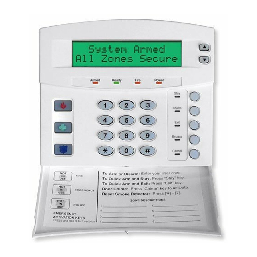
Page 8: Understanding The Lights
UNDERSTANDING THE LIGHTS Armed Light The armed light is “on” when the system is armed. The armed light is “off” when it is disarmed. The armed light will flash when there has been an alarm during the previous arm cycle. Bypass Light The bypass light is “on”... -
Page 9: Keypad Functions
KEYPAD FUNCTIONS ARMING YOUR SYSTEM IN THE “AWAY” MODE AWAY is utilized when the user is going away from the premise and wants the interior protected. Listed below are the steps to arm in the AWAY Mode: Step 1 Close all protected doors and windows. Ready light will be on or flashing when all protected System Ready... -
Page 10: Arming Your System In The "Stay" Mode
ARMING YOUR SYSTEM IN THE “STAY” MODE STAY is utilized when the user is inside the premise and wants protection around the perimeter. The steps to arm in the STAY Mode are as follows: Step 1 Close all protected doors and windows. Ready light must be on or flashing (force armed) when all protected zones and sensors are secure. -
Page 11: Using The Quick Arm
USING THE QUICK ARM The Quick Arm feature may be used if it is enabled. Quick Arm will allow the user to arm the security system in the AWAY mode by pressing the [EXIT] key. The system can be quick armed in the STAY mode by pressing the [STAY] key. This feature is used for ARMING ONLY, and will not disarm the security system. -
Page 12: Cancel / Abort Feature
CANCEL / ABORT FEATURE (Optional, if programmed) The cancel light will flash during an abort delay time. If a code is entered followed by the [CANCEL] key while this light is flashing, all abortable reports will stop the communication process. NOTE: The abort feature must be enabled. Entering a code followed by the [CANCEL] key during or after an alarm report to the central station will cause the cancel light to come on. -
Page 13: Group Bypass
If you do not know the number of the zone you wish to bypass, Procedure #2 use the following steps: Press r • Step 1 The description for zone 1 will be displayed. Use the • – scroll keys to browse through the custom descriptions Step 2 for the zones in this system. -
Page 14: Function Menu
Auxiliary Key - If programmed, you can activate the auxiliary alarm by pressing the Emergency Activation [Auxiliary] key for two seconds. If your system is connected to a monitoring center, an emergency report could be sent to that center. This key should only be pressed in an emergency situation requiring response by emergency personnel. -
Page 15: View Zone Status
VIEW ZONE STATUS Step 1 Press r • . The LCD Screen will display the zone status. Step 2 Use the • – scroll keys to browse through the descriptions. The LCD Screen will display the list of all zones in sequential order by zone number. Step 3 Press [#] to exit this function. -
Page 16: Display Test Function
DISPLAY TEST FUNCTION This function will perform a test of the LCD display. No alarms or reports will be sent. Step 1 Press r 5 . The test will be performed and all of the display pixels and LED indicators will flash until another key is pressed. Step 2 Press any key to end the test. -
Page 17: Changing User Codes
CHANGING USER CODES Press r Step 1 5 . The LCD Screen will prompt for a code. Step 2 Enter [master code]. The LCD Screen will prompt for a user number. NOTE: For partitioned systems, if you are changing the code of another person, you must have access to all partitions, or at least all of the partitions to which the other person has access. -
Page 18: Reset Function
PROMPT » DO NOT CHANGE THIS SEGMENT! Outputs used? Open / Close Rprt? (These are for use by a professional installer only.) Bypass enable? Arm / Disarm? Master code? 0=No 1=Yes Sched arm only? Your keypress will apply to the user code you entered in Arm only? Step 3. -
Page 19: Reading The Event Log
READING THE EVENT LOG The control panel has an event log that can be retrieved using a master code. This log contains a listing of the events along with date, time, and partition where the event occurred. To view the log, press r Step 1 0 . -
Page 20: Setting The System Clock
SETTING THE SYSTEM CLOCK Step 1 Enter r The LCD Screen will prompt for a code. Step 2 Enter [master code]. The time and date will be displayed with the current hour flashing. Step 3 Use the • – scroll keys to select the proper hour. Step 4 Press the r key to move to the minutes, day of week, date, month, and year. -
Page 21: Partitioned Systems Operation
PARTITIONED SYSTEMS OPERATION “ “ This system is is not partitioned. If your system is multi-partitioned and the keypad resides in one partition, your keypad will provide the status of the zones in your partitioning by using the screen messages described earlier in this manual. The Master Mode of operation allows you to temporarily access any partition (providing your code is authorized) within the system and to perform functions in other partitions. - Page 22 This display is reflecting all 8 areas are Ready 12345678 Ready, and Area 5 is disarmed. NOTE: If a Armed 1234-678 number is flashing on the Armed line, that area is armed Instant. If a number is flashing on the Ready line, that area is ready to be Force Armed.
- Page 23 OPERATING INDIVIDUAL AREAS IN THE MULTI-PARTITION MODE Enter a code that is a valid arm/disarm code for the area you wish to operate. The following display will appear on the LCD screen. Disarm º Only the areas authorized by this code will 12-4—78 appear.
-
Page 24: Keypad Control Tones (Beeps)
KEYPAD CONTROL TONES (BEEPS) A sounder is built into the keypad and may sound for any of the following reasons: Beeps for all keypresses. Sounds a continuous tone during the Entry delay time. Pulses when a day zone is violated while the system is disarmed. Pulses when a FIRE zone has a trouble condition. -
Page 25: Service Display
SERVICE DISPLAY The following message will be displayed periodically if the security system requires service. Call your service provider promptly if this message is observed. Service Required Type r2 for help If you see this display, press 2 . One or more of the following fault messages will be displayed. - Page 26 Expansion A box containing an expansion device Box tamper has been opened. Expansion An expansion power supply has a low Low Battery battery. Expansion A short circuit of an expansion devices’ Over-current power supply has occurred. Expansion The main power to an expansion power Power trouble supply is not on.
-
Page 27: Appendix A - Event Log
APPENDIX A - EVENT LOG NOTE: Your system may not have all of the features listed in this table. DISPLAY DESCRIPTION Transmitter The transmitter has a low battery. TXlobat Low Battery Zone Lost A wireless or multiplexed zone device is not ZN Lost reporting to the control. - Page 28 DISPLAY DESCRIPTION Cancel System is disarmed and the Cancel button was Cancel pressed within 5 minutes of an alarm. Gnd Flt Ground Fault A short to ground has been detected. Man Test Manual Test Bell and/or communicator test while system is in disarmed condition.
-
Page 29: Emergency Evacuation Plans
EMERGENCY EVACUATION PLANS An emergency evacuation plan should be established for an actual fire alarm condition. For example, the following steps are recommended by the National Fire Protection Association and can be used as a guide in establishing an evacuation plan for your building. - Page 30 SYSTEM NOTES...
- Page 32 NX-148E-CF USERS MANUAL NX148ECFUB03 REV B (MAY2003)
Need help?
Do you have a question about the NX-148E - Security NetworX LCD Keypad and is the answer not in the manual?
Questions and answers