
Related Manuals for Paramount Fitness ME II

Summary of Contents for Paramount Fitness ME II
- Page 1 The Paramount Robotic Telescope System User Guide Paramount ME II, M T, MX, and MX+ models Revision 1.94 August, 2015 Copyright 2015 Software Bisque, Inc. All rights reserved.
- Page 2 862 Brickyard Circle Golden, CO 80403-8058 Web Site: http://www.bisque.com The Paramount ME, Paramount ME II, Paramount MX, Paramount MX+, Paramount M T, Bisque TCS, MKS 4000, MKS 5000, and TheSkyX Professional Edition Astronomy Software are trademarks of Software Bisque, Inc.
-
Page 3: Table Of Contents
Paramount User Guide Table of Contents Telescope Operation Disclaimer ........................8 Sun Warning ..............................8 The Paramount Robotic Telescope System ....................9 Paramount Model Comparison ....................... 12 Optional Accessories ..........................14 Getting Help ..............................15 What You Need to Know ..........................15 Coordinate Systems .......................... - Page 4 Right Ascension Carrying Handle ......................72 RA Worm Block Switch ........................73 RA Spring Plunger and Cam Stop Access Hole (Paramount ME II and MX+ Only) ......77 RA Encoder Cover (Paramount ME II Only) ..................77 P a g e...
- Page 5 Declination Axis Three Position Switch (Paramount MX Dec Three Position Switch) ......88 Cable Conduit Access Hole and Cover ....................88 Right Ascension Axis Locking Hole (Paramount ME II Only) ............... 89 Configurable Hard Stop Positions (Paramount ME II Only) ..............90 Declination Axis Assembly (Dec Assembly) ..................
- Page 6 USB 2.0 Cable ............................ 111 Hex Wrenches ........................... 112 Power Supply Unit (PSU) ........................112 Altitude Adjuster Wrench (Paramount ME II Only) ................112 How To Polar Align ............................ 112 Rough Polar Alignment Method ......................113 Step-By-Step Rough Polar Alignment ....................113 Accurate Polar Alignment ........................
- Page 7 Paramount User Guide Logging Tab ............................164 Using ProTrack™ ............................164 ProTrack Minimum Requirements ....................164 Getting Started with ProTrack ......................165 Troubleshooting Mount Operation......................166 USB Hubs and USB Extenders ....................... 167 Controlling Multiple USB Devices with USB Hubs ................167 Windows and USB Port Power Settings ....................
-
Page 8: Telescope Operation Disclaimer
Paramount User Guide Telescope Operation Disclaimer Robotic telescope mounts do not have an unlimited range of movement. The telescope’s shape, the way it is mounted, or the addition of accessories can prevent it from pointing at particular parts of the sky. If the telescope is forced past these points, the telescope, its mounting, or accessories might be damaged. -
Page 9: The Paramount Robotic Telescope System
TheSkyX Professional Edition, create a formidable imaging system that can help you achieve your most lofty observing goals. This user guide covers the basic setup and use of the Paramount ME II, Paramount MX, Paramount MX+, and Paramount M T model mounts, as well as how to control your mount using TheSkyX Professional Edition. - Page 10 Both the right ascension and declination axes include mechanical switches to change quickly switch between balancing the payload and tracking. The Paramount ME II’s axes may be locked in place by installing locking bolts (page 89). The Paramount MX...
- Page 11 Paramount User Guide The control system supports a wide dynamic range for slewing and tracking rates. Virtually any slew speed is available between zero and several degrees per second. Configurable acceleration and deceleration rates during slews. Integrated homing sensors that allow rapid mount initialization to produce precision and reliable repeatability from night to night, or...
-
Page 12: Paramount Model Comparison
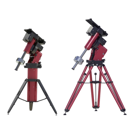
80W max 80W max 80W max Paramount Model Comparison The Paramount ME II, Paramount MX and Paramount MX+ are very similar in function and design. The table below lists the “significant” differences between these models. Feature or Specification Maximum payload... - Page 13 Paramount User Guide Feature or Specification 25 cm x 51 cm x 2.5 cm (9.9-in. x 20-in. x 16 cm x 41 cm x 16 cm x 41 cm x 15 cm x 35.6 cm x 1.0-in) 1.8 cm 1.8 cm 1.6 cm (6.4-in.
-
Page 14: Optional Accessories
See “Micro Levelers Base Plate Micro (Paramount ME II Not available. Not available. Not available. Levelers Only)” on page 108. Optional Accessories The table below lists optional accessories for each model. Optional Accessory Counterweight Shaft Extension 8-in. -
Page 15: Getting Help
Paramount User Guide Optional Accessory Latitude Adjustment Wedge for use below 10 degrees and above about 64 degrees latitude WiSky Wi-Fi Control Absolute Encoders Not available. Not available. Versa-Plate Spacers Not available. Not available. Optional Software Add Ons and Databases TheSkyX Professional Edition offers additional software Add Ons and astronomical databases. -
Page 16: Coordinate Systems
Paramount User Guide What are the differences between right ascension, azimuth and hour angle? Why does the meridian matter when operating a GEM? What exactly is synchronization? What is homing and what does it actually do? ... -
Page 17: The Equatorial Coordinate System
Paramount User Guide negative altitude are below the horizon. For example, the Sun just after sunrise is close to the horizon so it has an altitude of a couple of degrees, and just after sunset its altitude is minus one or two degrees. Azimuth The azimuth (az) of an object is generally reckoned from North, increasing in the clockwise direction, and ranges from 0 to 359 degrees. -
Page 18: Hour Angle
Paramount User Guide Right Ascension The geometry of the right ascension (RA) lines on the celestial sphere is the same as the longitude lines on Earth. Longitude lines divide the Earth into 360 degrees. Right ascension lines divide the celestial sphere into 24 hours, based on one revolution of Earth. -
Page 19: Local Sidereal Time
Paramount User Guide Hour angle can be used to describe a telescope’s mechanical orientation with respect to a horizon-based hemisphere. For Paramount mounts with AutoHoming™, when the mount finds home, the home position is a fixed, mechanical mount orientation. In the northern hemisphere, when homing is successful, the mount always points to hour angle 2 and declination 0. -
Page 20: Polar Alignment Basics
Paramount User Guide Except low down in the sky, the refraction goes roughly as the tangent to ZD, so at ZD = 70 degrees, or, at 20 degrees above the horizon, it is up to 165 arcseconds. (It reaches a 1800 arcseconds, or 0.5 degrees at the horizon.) ... - Page 21 Paramount User Guide The mount’s “TPoint unassisted pointing accuracy” will be disappointing, especially when the OTA switches sides of the pier. These symptoms may make you frustrated with the performance of your Paramount and leave you wondering, “What am I doing wrong?” Mastering the polar alignment techniques described below (or using your trusted method) is critical.
-
Page 22: Homing
Paramount User Guide Homing Mount synchronization is one of the least understood and most confusing processes for new Paramount users; understanding exactly what homing a Paramount does is a very close second. Please carefully read the following to avoid falling into the “my mount is not homing to the correct position”... -
Page 23: Labeling The Home Position On The Sky Chart
Paramount User Guide Subsequent observing sessions use TheSkyX Professional Edition’s local sidereal time to determine the mount’s equatorial coordinates. Make sure the computer’s clock is accurate (page 29). Homing provides the following benefits. Once a mount is aligned with the celestial pole and homed, repeatable and accurate pointing from night to night can be achieved using TheSkyX Professional Edition and the TPoint Add On. -
Page 24: Physically Marking The Home Position
Paramount User Guide 3. Choose the Connect command from the Telescope menu. The mount Status text will show Homed. 4. Choose the Find Home command from the Start Up pop-up menu on the Telescope window. The mount will slew to the home position. The mount Status text will show Synced. -
Page 25: Synchronization
Paramount User Guide The wrong star was centered in the eyepiece when the mount was synchronized. Improper synchronization results in the telescope cross hairs to be displayed at the wrong spot on the Sky Chart. And this error is particularly apparent after the mount is homed. Many come to the incorrect conclusion when the telescope cross hairs on the Sky Chart are wrong, there must be something wrong with the homing process. -
Page 26: Best Synchronization Practices
Paramount User Guide in the eyepiece, identifying this star in TheSkyX Professional Edition then choosing the Synchronize command from the Start Up pop-up menu on the Telescope window. Once the Paramount has been synchronized on a star, TheSkyX Professional Edition uses the equatorial coordinates of the star to determine the mount’s mechanical orientation and software slew limits. -
Page 27: Session To Session Pointing Repeatability
Paramount User Guide Errors in latitude “appear” to TPoint as a vertical misalignment in the polar axis, and will pollute synchronization (and the TPoint model, if one is in place). If your time zone is off by one hour or more, then pointing will be off by the same amount. -
Page 28: Making Sure Synchronization Is Correct
Paramount User Guide Note that during the process of polar alignment, you will be required to synchronize the mount several times (each time the mount is adjusted to a new altitude and/or azimuth). For permanent installations, once the mount is sufficiently aligned with the celestial pole, it should not have to be synchronized again unless the optical tube assembly or the telescope’s physical mounting changes. -
Page 29: The Local Celestial Meridian
Paramount User Guide The Sky Chart provides graphical feedback to help verify the mount is synchronized correctly and identifies the regions near the meridian that have unique behavior when tracking or slewing. While TheSkyX Professional Edition is connected to the Paramount, two regions are drawn near the meridian. If the regions are centered on the meridian, then the synchronization is most likely correct. -
Page 30: Maintaining Accurate Time
Paramount User Guide From TheSkyX Professional Edition, expand Reference Lines and Photos in the Chart Elements window and turn on the Meridian checkbox. Figure 6: TheSkyX Professional Edition with the meridian reference line turned on. The arcing line in Figure 6 represents the local celestial meridian. When the Paramount is at the home position, the telescope must be pointing to the west side of the meridian, near hour angle 2 and declination 0 in the northern hemisphere. -
Page 31: Parking The Paramount
Paramount User Guide Always perform “reality check” by comparing the coordinates of objects in TheSkyX Professional Edition to objects in the night sky. If TheSkyX Professional Edition’s location or time is not accurate, the two will not match! Choose the Verify TheSkyX Time command on the Tools menu to compare the computer’s date, time and time zone settings with a web-based time source. -
Page 32: Defining The Park Position
Since the Paramount allows the OTA to slew past the meridian (two hours maximum for the Paramount ME II and 2.5 hours for the Paramount MX and Paramount MX+) before flipping sides, you have now defined a park position that will cause the mount to slew to a different orientation than when the park position was defined. - Page 33 Paramount User Guide of the control system electronics; two successive beeps (usually occurring a few seconds or so apart) indicate servomotor initialization success. The three LEDs on the Electronics Box, labeled TCS, RA, and Dec, provide additional visual feedback of mount initialization. See “Electronics Box Components” on page 78 for details.
- Page 34 Paramount User Guide Sound Occurs Description Attempting to slew or home the mount from TheSkyX Professional Edition before servomotor initialization. For normal initialization, simply turn on the mount and wait for the two successive beeps, without attempting to control the mount via joystick or TheSkyX Professional Edition.
-
Page 35: Visual Control System Feedback
Paramount User Guide Sound Occurs Description Variable-pitched After motor initialization When the Paramount is turned on and initialized, the high-frequency and whenever the mount is servomotors emit an audible, variable-pitched “humming” powered on and tracking. sound. This sound is the result of the control system checking and adjusting the position of the servo–... - Page 36 Paramount User Guide In both cases, the rotating internal shaft creates a potentially dangerous pinch point with the outer declination axis assembly that can cut, crush or sever fingers. Always keep fingers clear during mount slews and use extreme caution when routing cables through the mount, or aligning the declination shaft’s “through-hole”...
- Page 37 Paramount User Guide 1. Make sure the additional cable is long enough to go from the Instrument Panel (or from a device mounted on the OTA), through the mount and to its destination, then add an additional eight to 10 inches to accommodate a loop in the declination axis (described below). 2.
- Page 38 Paramount User Guide Figure 9: Close up view showing the proper routing of the through the Paramount MX and Paramount MX+ declination axis. A 24-inch flexible wire grabber can help pull stiffer cables through the mount and up to the Instrument Panel, even when an OTA is in place. Figure 10: A flexible wire grabber.
- Page 39 Paramount User Guide Routing Cables through the Paramount ME II Figure 11: Paramount ME II cross section showing path of cable through the mount. Routing custom cables through the Paramount ME II is a relatively straightforward procedure. 1. Remove the two Right Ascension Rear Cover (Figure 20) mounting screws and the cover.
- Page 40 Figure 12: Paramount M T cross section showing path of cable through the mount. Compared to the both the Paramount MX, Paramount MX+, and Paramount ME II, routing custom cables through the Paramount MyT is an even more relatively straightforward procedure.
-
Page 41: Packing List
8. Unlike the Paramount ME II, Paramount MX and Paramount MX+, there is no need for a loop around the declination shaft. The shafts have been re-designed so the cables have a more straightforward path to the instrument panel. - Page 42 Paramount User Guide Photo Description Paramount MX Robotic Telescope Mount with Versa-Plate attached. Box Dimensions: 33 cm x 62 cm x 66 cm (13" x 24.5" x 26") Shipping Weight (including the Paramount MX): 29 kg (65 lb.) Photo Description Paramount MX+ Robotic Telescope Mount with Versa-Plate attached.
-
Page 43: Important Packing Material Notes
Paramount User Guide Photo Description Paramount M T Robotic Telescope Mount with Versa-Plate attached. Box Dimensions: 48 cm x 51 cm x 24 cm (19" x 20" x 9.5") Shipping Weight (including the Paramount M mount): 20.4 kg (45 lb.) Important Packing Material Notes The Paramount is shipped encased in two ultra-dense white Styrofoam inserts inside two double-walled cardboard shipping boxes. -
Page 44: Box 2 Contents (Accessories Box)
Paramount User Guide Box 2 Contents (Accessories Box) Photo Description The printed Paramount User Guide. USB 2.0 cable. Base Thrust Mounting Knobs (page 84). Hex key wrench set. 44 | P a g e... - Page 45 Paramount MX, Paramount MX+ and Paramount M T PSU Power Supply Extension Cable (Paramount ME II only). See “Plugging Power Supply Unit into the Electronics Box” on page 80 for details. Power Cable for the Power Supply Unit (NEMA 5-15 male plug).
- Page 46 Two 9 kg / 20 lb. Two 9 kg / 20 lb. One 9 kg / 20 lb. Paramount ME II (only) Altitude Adjuster Wrench (page 112). Paramount ME II (only) Accessory Pouch Use this pouch to store the following items: ...
-
Page 47: Locating Your Serial Numbers
Paramount User Guide Photo Description One (1) Paramount Software Suite thumb drive in jewel box. Locating Your Serial Numbers The Paramount mount and the Paramount Software Suite serial number are printed on a card that is attached to the altitude adjuster (Figure 13). Please retain this card for your permanent records. Figure 13: The Paramount serial numbers are attached to the altitude adjuster. -
Page 48: Paramount And Software Serial Number Registration
Paramount User Guide Your Paramount Software Suite serial number should be entered the first time TheSkyX Professional Edition is launched. Doing so also automatically activates the Add Ons. Paramount and Software Serial Number Registration Please register the Paramount hardware and software serial numbers at: http://www.bisque.com/register Serial number registration gives your Software Bisque web account access to software installers, software updates, control system firmware updates (page 151) and the latest MKS 5000 USB drivers (page 170). -
Page 49: Paramount Me Ii Unpacking Insert
Paramount User Guide Paramount ME II Unpacking Insert Figure 14: Please carefully read the above flyer and the warning below before unpacking the Paramount ME II. 49 | P a g e... -
Page 50: Paramount Mx Unpacking Insert
Paramount User Guide Paramount MX Unpacking Insert Figure 15: Please carefully read this flyer before unpacking the Paramount MX. Please see the “RA Worm Block Switch” on page 73 for details about using the three position switch. 50 | P a g e... -
Page 51: Paramount Mx+ Unpacking Insert
Paramount User Guide Paramount MX+ Unpacking Insert Figure 16: Please carefully read this flyer before unpacking the Paramount MX+. Please see the “RA Worm Block Switch” on page 73 for details about using the two position switch. 51 | P a g e... -
Page 52: Paramount M Y T Unpacking Insert
Paramount User Guide Paramount M T Unpacking Insert Figure 17: Please carefully read this flyer before unpacking the Paramount M The Paramount M T right ascension axis can be locked at one of three unique orientations (Figure 18). Figure 18: The three Paramount M T right ascension axis locking positions. - Page 53 Paramount User Guide The declination axis can be locked at one of four unique positions, each 90 degrees apart (Figure 19). Figure 19: The four Paramount M T declination axis locking positions. 53 | P a g e...
-
Page 54: Packing The Paramount For Transport
Paramount User Guide 1. When the declination axis is rotated fully clockwise, and the long axis of the Versa-Plate is parallel to the wedge plates. 2. Starting from the orientation in Step 1, rotate the Versa-Plate 90 degrees counterclockwise. 3. Starting from the orientation in Step 1, rotate the Versa-Plate 180 degrees counterclockwise. 4. -
Page 55: Paramount Components
Paramount User Guide Model How to unlock axis… Remove the locking shoulder bolts (page 89). Rotate the right ascension axis and declination axis Three Position Switch to the Balance position. Pull and rotate the transportation lock knob clockwise to the Balance position and make sure the worm and gear are disengaged by rotating both axis a few degrees back and forth. -
Page 56: Paramount Me Ii Front View
Paramount User Guide Paramount ME II Front View Figure 20: The front view of the Paramount ME II. 56 | P a g e... -
Page 57: Paramount Mx Front View
Paramount User Guide Paramount MX Front View Figure 21: The front view of the Paramount MX. 57 | P a g e... -
Page 58: Paramount Mx+ Front View
Paramount User Guide Paramount MX+ Front View Figure 22: The front view of the Paramount MX+ 58 | P a g e... -
Page 59: Paramount M Y T Front View
Paramount User Guide Paramount M T Front View Figure 23: The front view of the Paramount M RA Worm Block Cover Always keep hands and fingers away from the right ascension axis worm block cover! A “pinch point” is created as the declination axis rotates past the right ascension axis worm block cover. -
Page 60: Payload Mounting Plate (Versa-Plate)
Paramount User Guide Figure 24: Caution: Always keep hands clear of this area! Payload Mounting Plate (Versa-Plate) The Paramount Versa-Plate provides a stable mounting platform to carry a variety of astronomical equipment. The optical tube assembly can be attached using the integrated Losmandy and Celestron dovetail rail-compatible dovetail, a telescope cradle, or telescope mounting rings. - Page 61 Paramount User Guide Figure 25: The Paramount ME II Versa-Plate technical specifications. Figure 26: The Paramount MX and MX+ Versa-Plate technical specifications. 61 | P a g e...
- Page 62 Paramount User Guide Figure 27: The Paramount M T Versa-Plate technical specifications. The table below lists the most common hardware used to mount telescopes (or optical tube assemblies) and the advantages and disadvantages of each system. OTA Mounting Advantages Disadvantages ...
-
Page 63: Paramount Versa-Plate Knobs
The Versa-Plate Knobs (three on the Paramount MX, Paramount MX+ and Paramount M T, four on the standard Paramount ME II; up to six with the optional Large Dovetail Accessory Rail) are designed to securely captivate a male Losmandy-compatible dovetail. Rotating the knob clockwise advances an angled brass plunger on the inside of the dovetail. - Page 64 Figure 29: Machined circles mark the four mounting positions on the Paramount MX and Paramuont MX+ Versa-Plate. (The Instrument Panel end is to the left.) The Paramount ME II’s Versa-Plate has two mounting positions. 64 | P a g e...
- Page 65 Paramount User Guide Figure 30: The Versa-Plate mounting slots on the Paramount M T allow the payload to be adjusted to achieve balance in declination. The Paramount M T Versa-Plate has four slots that can be used to adjust the balance point of the payload in declination.
- Page 66 The top of the declination axis on later model Paramount ME II, Paramount MX+ mounts, and all Paramount MYT mounts have an arrow and star machined into the top of the declination axis (Figure 31). For these...
- Page 67 Versa-Plate Cable Spacers (Paramount ME II only, Optional) Software Bisque offers optional spacers that can be used when the Paramount ME II Versa-Plate is mounted in the wide orientation. When mounted to the top of the declination axis, the spacers create a...
-
Page 68: Large Dovetail Accessory Rail (Paramount Me Ii Only, Optional)
Large Dovetail Accessory Rail (Paramount ME II only, Optional) The Paramount ME II can accept optical tube assemblies with a PlaneWave Instruments dovetail mounting plate using the optional Large Dovetail Accessory Rails. Four “rails” and the rotating safety knob mount directly to the existing Versa-Plate and offer six mounting knobs to securely attach and carry 20-inch class optical tubes. - Page 69 Paramount User Guide Powering Devices (Power Out) The Instrument Panel port labeled Power Out is the output port for the mount’s built-in through the mount power cabling. The input port for the through the mount cabling is labeled Power In on the Electronics Box (page 78).
- Page 70 Paramount User Guide USB Ports (USB A and USB B) These two USB ports are part of an integrated USB hub on the MKS 5000 electronics board. The Instrument Panel’s two USB ports can connect any two USB 2.0 devices to a computer’s USB port. To allow USB communication between these ports and the computer, plug the square end of the mini- USB cable to the Electronics Box’s mini-USB port and the flat end into your computer’s USB port.
- Page 71 Paramount User Guide Autoguiding, which involves monitoring the position of a guide star and adjusting the mount’s position as the star moves, has traditionally be performed using a guider cable attached to the camera’s guider port and the telescope’s guider port as described above. Software Bisque’s DirectGuide feature eliminates “relay based”...
-
Page 72: Ra Worm Block Cover
Use the integrated carrying handle to lift the mount. On the Paramount MX, place the Three Position Switch in the Lock position before lifting the mount. The Paramount ME II’s RA Cable Conduit access hole is dome-shaped and serves as the integrated carrying handle (remove the RA Gear Cover to access it). The Paramount MX+ has no integrated carrying handles but underneath the electronics box can serve as an aid when carrying the mount. -
Page 73: Ra Worm Block Switch
The Paramount’s RA and Dec Axis have an arrow-shaped knob as part of a rotatable, mechanical switch. (The Paramount ME II and Paramount MX+ switch has two positions and is referred to as the Two Position Switch. The Paramount MX switch has three positions and is referred to as the Three Position Switch). - Page 74 Separate locking bolts must be installed lock the axis in place. See “Right Ascension Axis Locking Hole (Paramount ME II Only)” on page 89 and “Declination Axis Locking Hole (Paramount ME II Only)” on page 108 for details about locking the Paramount ME II axes. 74 |...
- Page 75 Paramount User Guide Model Mechanical Switches The balance, star and lock symbols shown are etched into the top of the cover of the Paramount MX, where they are most visible when setting up the mount (Figure 36). The Balance, Star, and Lock positions (Figure 37) are etched on the front of the Paramount MX+ worm block covers.
- Page 76 Paramount User Guide Track Position: Rotate the arrow on the switch fully counterclockwise to engage the worm with the gear. This position is used during normal mount operation. Balance Position: Rotate the arrow on the switch to the center position to disengage the worm from the gear so that the axis rotates freely.
-
Page 77: Ra Spring Plunger And Cam Stop Access Hole (Paramount Me Ii And Mx+ Only)
Note that the entire knob will rise slightly out of the worm block cover when in the unlocked position. RA Spring Plunger and Cam Stop Access Hole (Paramount ME II and MX+ Only) This hole provides access to the spring plunger and cam stop adjustment. See the Paramount Cam Stop Adjustment Instructions document here: http://www.bisque.com/sc/media/p/75503.aspx... - Page 78 Paramount User Guide Figure 39: Technical drawing of the Paramount MX and Paramount MX+ Electronics Box labeling each component. Figure 40: Photograph of the Paramount ME II Electronics Box. Electronics Box Components External Power (Power In) This 4-pin DC power connector can be used to run up to 20V at up to 7.5 amps DC maximum power through the mount to the Instrument Panel.
- Page 79 External Power connector located in the Electronics Box to the External Power connector in the Instrument Panel. Do not plug the Paramount ME II power supply into this port! See “Power Input (48V Power In)” on page 80 for instructions on how to supply power the Paramount ME II.
- Page 80 The Paramount MX PSU can be plugged directly into the 48V Power In port on the Electronics Box; the Paramount ME II and Paramount MX+ requires an additional power extension cable. The table below describes how to physically connect the PSU of each model from the external power source to the 48V Power In port (page 80) on the Electronics Box.
-
Page 81: Polar Axis Adjustments
For now, there is no reason to remove this cover. Polar Alignment Scope Mounting The Paramount ME II, Paramount MX and Paramount MX+ can be fitted with an optional polar alignment scope to optically align the mount’s polar axis with the celestial pole. The Paramount Polar Alignment... -
Page 82: Azimuth Adjuster Knobs
Paramount User Guide The Paramount base consists of an outer, fixed plate that is mounted to the pier, and an inner rotating plate on which the mount sits. Adjustments in azimuth are achieved by rotating the Azimuth Adjustment Knobs at the front of the mount (Figure 43). For a level mount, rotation of this plate does not affect the altitude of the polar axis. - Page 83 Paramount User Guide Figure 43: Rotate the Azimuth Adjuster Knobs to adjust the azimuth axis (Paramount MX pictured above). Azimuth Vernier Scale Both Azimuth Adjuster Knobs include Vernier scales that can be used for refining the position of the azimuth axis. The longest tic marks represent approximately 4 arcminutes rotation in azimuth. The medium length marks are approximately 2 arcminutes rotation and the shortest tics marks are approximately 1 arcminute.
-
Page 84: Base Thrust Mounting Knobs
3.8 cm (1.5 in.) 3/8-inch, 24 threads per inch UNF The Paramount ME II base plate also includes integrated micro levelers than can help level the Base Plate on a slightly uneven mounting surfaces. Please carefully read “Micro Levelers (Paramount ME II Only)”... -
Page 85: Paramount Me Ii Rear View
Paramount User Guide Paramount ME II Rear View Figure 44: The rear view of the Paramount ME II. 85 | P a g e... -
Page 86: Paramount Mx Rear View
Paramount User Guide Paramount MX Rear View Figure 45: The rear view of the Paramount MX. 86 | P a g e... -
Page 87: Paramount Mx+ Rear View
Paramount User Guide Paramount MX+ Rear View Figure 46: The rear view of the Paramount MX+. 87 | P a g e... -
Page 88: Declination Carrying Handle (Paramount Mx Only)
Paramount User Guide Figure 47: The rear view of the Paramount M Declination Carrying Handle (Paramount MX Only) Use the integrated carrying handle (located above the Declination Three Position Switch) to lift the mount. Remember to always place both Three Position Switches in the Lock position before lifting the mount (page 73). -
Page 89: Right Ascension Axis Locking Hole (Paramount Me Ii Only)
Right Ascension Axis Locking Hole (Paramount ME II Only) The Paramount ME II’s right ascension axis can be locked into one, and only one, position by orienting the counterweight shaft vertically and then inserting two shoulder bolts (supplied with mount) into both Right Ascension Axis Locking Holes and through the right ascension gear. -
Page 90: Configurable Hard Stop Positions (Paramount Me Ii Only)
1/4 in.–20 thread The declination axis locking shoulder bolt has the same specifications, but is 1 3/4-in. long. Configurable Hard Stop Positions (Paramount ME II Only) The Right Ascension Locking Holes also provide access bolts that define the Paramount ME’s configurable hard stop position. -
Page 91: Paramount Serial Number (Serial Number)
Paramount User Guide Paramount Serial Number (Serial Number) The Paramount’s serial number is permanently affixed to the base of the right ascension assembly. It also appears on your invoice or packing slip (page 47). Altitude Scale The Altitude Scale is a series of tic marks machined into the edge of both altitude wedge plates. On the Paramount MEII, MX, and MX+, the longer tic marks represent approximately ten degree increments, the medium tics are approximately five degree increments and the shorter tics are approximately one degree increments. - Page 92 10° 0° (min.) 14° (min.) 10° (min.) Figure 49: Altitude Scales for the Paramount ME II, Paramount MX/MX+ and Paramount M Maximum Elevation (°) Model Minimum Elevation (°) *The Paramount MX and Paramount MX+ polar axis can actually be adjusted to exceed the maximum scale by about one degree, so that the highest “reachable”...
-
Page 93: Altitude Adjuster
Figure 50: The tic mark that is aligned with the bottom of the Altitude Reference Block represents the polar axis altitude for the Paramount ME II, Paramount MX and Paramount MX+. Figure 51: The arrow machined into the right ascension base plate points to the altitude of Paramount M T polar axis. - Page 94 2. Rotate the large central knob (near the arrow in Figure 52) to raise or lower the polar axis. The Paramount ME II includes a removable Altitude Adjuster Wrench (page 112) to help rotate the Altitude Adjuster Knob, even with the heavy payloads.
- Page 95 Paramount User Guide Once the polar axis has been placed at the approximate latitude using the coarse adjustment, the fine adjustment can be used to refine the polar axis altitude when the mount is loaded with equipment and counterweights. Adjusting the Paramount M T Polar Axis: 1.
- Page 96 The arrow on Figure 55 shows the location of the fine-position Vernier scale for the Paramount MX, Paramount MX+ and Paramount ME II. This scale shows elevation adjustments from approximately +10 to –10 arcminutes. The medium height tick marks represent approximately 5 arcminute divisions; the small tic marks represent approximately 1 arcminute divisions.
- Page 97 4.5 tic mark on the Vernier scale”. You can subsequently use this position to precisely restore the altitude of the polar axis each time the mount is setup. Figure 55: The Vernier scale on the Altitude Adjuster for Paramount MX, MX+ and ME II. Paramount M...
-
Page 98: Counterweight Shaft
Paramount User Guide Figure 56: When making fine adjustments, align the edge of the knob with the stationary tic mark to determine relative motion. Counterweight Shaft To attach the stainless steel counterweight shaft to the Paramount, insert the threaded end into the bottom of the declination assembly (Figure 45) and rotate the shaft clockwise until it is hand tight. -
Page 99: Counterweight Shaft Extension Bar (Optional)
14 kg (30 lb.), 1.875 in. bore Technical drawing URL: http://www.bisque.com/sc/media/p/74654.aspx In addition to the 1.875-in. diameter counterweight shaft, the Paramount ME II can also accept the 1.5-in. diameter Paramount ME/MX counterweight shaft. 9 kg (20 lb.), 1.5 in. bore Technical drawing URL: http://www.bisque.com/sc/media/p/70864.aspx... - Page 100 Paramount MX, place the Three Position Switch in the Lock position first (page 73), for the Paramount ME II install the locking bolts and place the Two Position Switch to balance, and for the Paramount MX+ place the Two Position Switch to balance and pull and rotate the transport lock knob 90 degrees to a lock position.
-
Page 101: Payload Imbalance Cause And Effect
Paramount User Guide Figure 58: The Paramounts in their “happy place” with the counterweight shaft oriented vertically. Payload Imbalance Cause and Effect When the counterweight shaft is oriented “non-vertically” and one or more counterweights are on the counterweight shaft, and the right ascension axis is in the Track position, the extreme lateral force placed on the worm and gear forces them to separate. -
Page 102: Counterweight Safety Knob
Paramount User Guide vertically, then slide the counterweights up or down on the counterweight shaft to change the balance point. Always use extreme care when balancing the telescope! Make note of the weight distribution on the telescope before placing the mount’s mechanical switch in the Balance position. -
Page 103: Paramount Me Ii Side View
Paramount User Guide Paramount ME II Side View Figure 59: The side view of the Paramount ME II. 103 | P a g e... -
Page 104: Paramount Mx Side View
Paramount User Guide Paramount MX Side View Figure 60: The side view of the Paramount MX. 104 | P a g e... -
Page 105: Paramount Mx+ Side View
Paramount User Guide Paramount MX+ Side View Figure 61: The side view of the Paramount MX+. 105 | P a g e... -
Page 106: Altitude Adjuster Thrust Knobs
Make sure to completely loosen each knob (four on the Paramount ME II and two on the Paramount MX and Paramount MX+) before attempting to rotate the Altitude Adjuster. -
Page 107: Bubble Level
Paramount User Guide Model Minimum and Maximum Altitude of Wedge 14° – 68° URL for Latitude Adjustment Wedge (for latitudes outside this range): https://www.bisque.com/sc/shops/store/Latitude-Adjustment-Wedge.aspx 10° – 65° URL for Latitude Adjustment Wedge (for latitudes outside this range): http://www.bisque.com/sc/shops/store/MXLatitudeAdjustmentWedge.aspx 0° – 64° Bubble Level The Paramount bubble level is suitable for the most demanding astronomy work, and can make polar alignment easier when no polar alignment scope is available. -
Page 108: Declination Axis Locking Hole (Paramount Me Ii Only)
3 mm or 1/8-inch. The Micro-Levelers are also used to ensure that the base plate of the Paramount ME II is not distorted by an uneven mounting surface. Important note: the Micro-Levelers must protrude slightly below the surface of the Base Plate before tightening the Base Plate Attachment Knobs. - Page 109 Paramount User Guide The best approach for leveling the mount is to simultaneously rotate two Micro-Levelers so that the mount is tilted either north/south or east/west. The accuracy of the leveling required depends on the long-term use of the mount. If the mount is attached to a permanent pier, without the intent of portable use, leveling is less important.
-
Page 110: Hand Controller
Paramount User Guide To make sure this occurs, before tightening the Base Plate Attachment knobs, rotate each Micro-Leveler clockwise until it makes contact with the mounting surface. Then tighten it about 1/16 of a turn (or so) more. Additional adjustment may be required to accommodate uneven mounting surfaces. -
Page 111: Other Paramount Accessories
Paramount User Guide Rock and click the switch downward (toward the bottom of the hand paddle) to turn on and illuminate the bright red LED located on the top of the housing. The hand paddle now acts as a night-vision preserving flashlight. -
Page 112: Hex Wrenches
10 degrees per second. Altitude Adjuster Wrench (Paramount ME II Only) The Paramount ME II includes a removable Altitude Adjuster Wrench that makes rotating the Altitude Adjuster Knob easy, even with the heaviest payloads. The circular section of this wrench fits over the Altitude Adjuster Knob and will drop into place on the top of the knob when the wrench and knob tics are aligned. -
Page 113: Rough Polar Alignment Method
Paramount User Guide Rough Polar Alignment Method When the base of the Paramount is level, and the Paramount is at the home position, the fixed mechanical orientation of this position can be used in conjunction with TheSkyX Professional Edition to polar align the mount to within about 5-10 arcminutes of celestial pole (which is a good starting point). -
Page 114: Accurate Polar Alignment
Paramount User Guide Figure 67: The OTA’s optical and mechanical non-perpendicularity errors degrade the accuracy of the rough polar alignment method. Note that optical and mechanical non-perpendicularities in the telescope and the declination axis play a key factor in the accuracy of the rough polar alignment method. If these misalignments are large (in the order of 30 arcminutes or greater), the initial polar alignment will not be as accurate. -
Page 115: Using The Polar Alignment Scope
Paramount User Guide Once this process is completed, the mount should be aligned with the pole. Using the Polar Alignment Scope After mounting the polar alignment scope to the front of Paramount (page 81), follow the manufacturer’s instructions to calibrate the scope, and then place Polaris in the polar scope’s reticule. 115 | P a g e... -
Page 116: The Paramount And Theskyx Professional Edition
The MKS 5000 is included with the Paramount ME II, Paramount MX, Paramount MX+, and Bisque TCS units shipped after December 2012. (An optional MKS 5000 upgrade is planned for Paramount ME mounts at some point in the future.) ... -
Page 117: First Time Paramount Setup
One Paramount power supply (included). -Or- An optional 48V Paramount ME II/MX Portable Power Supply. This battery comes in 5AH and 10AH models and can be purchased from the Software Bisque Store. First Time Paramount Setup Please make sure to carefully read the instructional insert in the Paramount box before unpacking the mount. -
Page 118: Mac Os X
3. On the Imaging System Setup window, highlight Mount in the Imaging System list. 4. Select the Choose command from the Mount Setup pop-up menu. 5. Expand Software Bisque, select Paramount ME II, Paramount MX or Paramount MX+ and click 6. Choose the Settings command from the Mount Setup pop-up menu. -
Page 119: Getting Started With Theskyx Professional Edition
Paramount User Guide On Windows, select the COM port number assigned to the Paramount MX/MX+’s USB port (see page 171 for details about installing the MKS 5000 driver) and click OK. The Description of the Port in the Serial Port list will appear as Software Bisque MKS 5000. -
Page 120: The Bisque Tcs Window
Paramount User Guide Feature Quick Start Reference Parking Park command from the Shut Down pop-up menu on the Telescope window Setting the Park Position Set Park Position command from the Shut Down pop-up menu on the Telescope window Slewing Slew button on the Telescope window Star Searching Star Search command from the Tools pop-up menu on the Telescope window... -
Page 121: Status Messages (Status Text)
Paramount User Guide window. If the Telescope window is hidden, click the Telescope command from the Display menu to show Figure 69: The Parameters tab of the Bisque TCS window. The Bisque TCS window includes the Parameters, Show Status, Periodic Error Correction, Utilities and Logging tabs. - Page 122 5 degrees per second in declination, so the maximum default slew rate is approximately 3.2 and 4.5 degrees per second. The Paramount ME II’s maximum slew rate is over 4 degrees per second in both axes. 122 | P a g e...
- Page 123 Paramount User Guide Common Parameter Name Description The Paramount MX’s maximum slew rate in both right ascension and declination is 4 degrees per second. The default maximum slew rate in both axes is 3.6 degrees per second. The Paramount MX+’s maximum slew rate and default maximum slew rate in both right ascension and declination is the same as the Paramount MX, with the included power supply unit.
-
Page 124: Advanced Parameters
The default value of this parameter is minus 1.0 (–1.0) for the Paramount MX and Paramount MX+ and minus 0.3 (–0.3) for the Paramount ME and minus 3.0 (–3.0) for the Paramount ME II. Focus Pulse Slow The number of milliseconds the built in focuser will be pulsed when the SLOW focus button is pressed. - Page 125 Paramount User Guide Axis Parameters Description The general rule of thumb is that the fewer number of corrections to the mount’s position that are made during autoguided exposures the better the resulting star profile. So, a guide rate of fifty-percent of sidereal rate (the default setting) is the optimal value to achieve this goal.
- Page 126 Position the mount's mechanical homing sensor location. The Paramount ME, Paramount ME II, Paramount MX and Paramount MX+’s home position is hour angle (HA) 2.0 and declination 0.0 in the northern hemisphere and HA –2.0 and declination 0 when the mount is configured for the southern hemisphere (see “Hemisphere Setup”...
- Page 127 Paramount User Guide Axis Parameters Description Temperature Slew Rate Reduce the slew rate by this percentage when the ambient temperature Reduction Percentage drops below the Temperature Slew Rate Threshold value. Temperature Slew Rate When the ambient temperature, in Celcius, drops below this value, Threshold reduce the slew rate by the Temperature Slew Rate Reduction Percentage.
- Page 128 Paramount User Guide Axis Parameters Description For the Paramount ME II, MX and MYT, the motor index angles are 200 for the right ascension axis, and 3850 for the declination axis. Replacement MKS 5000 boards are normally pre-programmed with the correct motor index angles before shipment.
- Page 129 Defines the physical telescope mounting type: 0 = German Equatorial Mount. 1 = Asymmetric equatorial fork mount. Sync Version 0 = Paramount ME, Paramount ME II, Paramount MX, Paramount MX+, Paramount M T and Bisque TCS mounts. 1 = Paramount GT-1100S mount.
- Page 130 Paramount User Guide Axis Parameters Description Paramount MX+ Paramount M Bisque TCS Debug Output? Set this value to 1 to show control system diagnostics. Startup Test Joystick RA If set to 1, then Bisque TCS will abort startup and emit a single beep if the joystick is not centered when power is turned on.
-
Page 131: Commands Pop-Up Menu
Paramount User Guide Axis Parameters Description User-Defined Parameters Acceleration The motor's relative acceleration/deceleration setting. Lower numbers (for example, 250) will yield slow acceleration/deceleration while higher numbers (for example, 750) will yield very fast acceleration. Max Slew Speed (%) The percentage of the mount's maximum slew rate that is used to slew the mount. - Page 132 Figure 71: The Bisque TCS Configuration window. The right side of the Bisque TCS Configuration window lists the mount models that use the MKS control system. Paramount ME Paramount ME II Paramount MX Paramount MX+ ...
- Page 133 Paramount User Guide Save All Parameters to Mount Choose this command to save the mount’s parameters to the control system’s flash memory. Saving every parameter to the mount’s flash memory is a relatively lengthy operation and this command may require 15 seconds or so to complete.
- Page 134 Paramount User Guide MKS_JOY_CENTER 2184 , 2184 MKS_USER1_TICS360 12000000 , -12000000 MKS_USER1_dEXPECTED_HOME 2.0000000 , 0.0000000 MKS_USER1_dHOME_SENSOR 2.0000000 , 0.0000000 MKS_USER1_dBASE_RATE_PERC 100.0000000 , 0.0000000 MKS_USER1_dCREEP_RATE_ASPS 0.0000000 , 0.0000000 MKS_USER1_dGUIDE_RATE_FACT 0.5000000 , 0.5000000 MKS_USER1_dMAX_SLEW_PERC 90.0000000 , 90.0000000 MKS_USER1_NMOUNT_TYPE MKS_USER1_SYNC_VERSION 10000 MKS_USER2_NVERSION MKS_USER2_FOCUS_AXIS MKS_OTHER_MOUNT_ID , Paramount MX MKS_OTHER_DEBUG_OUTPUT...
-
Page 135: Show Status Tab
Paramount User Guide Show Status Tab The spreadsheet on the top of Status tab shows the current control system and motor status values for both the right ascension and declination axes. These values are useful for verifying the current tracking rate, slew limit conditions and other control system settings. - Page 136 Try unplugging the guider cable from the Electronics Box on the Paramount ME II, MX, or MX+, or, from both the Adaptor Panel and the Instrument Panel on the Paramount ME. If the relays are now closed, replace the guider cable.
-
Page 137: Periodic Error Correction Tab
Paramount User Guide A black-filled square indicates that the joystick is centered and the mount is not slewing via the joystick inputs. A green-filled square indicates that the joystick is issuing slew commands to the highlighted axis. Note that the joystick handle can be moved diagonally so as to issue slew commands both axes at once (N, E, S, W or NE, NW or SE, SW). -
Page 138: Bisque Tcs Pec Table Tab
Paramount User Guide As an example of periodic error versus seeing versus image scale, if the mount’s peak to peak periodic error is two arcseconds, and the local seeing conditions average three arcseconds, then the tracking error caused periodic error is less than the tracking errors caused by seeing conditions, so correcting the mount’s periodic error is not critical. - Page 139 Paramount User Guide The shaded purple region shows a graph of the mount’s periodic error or PEC table. The X-axis represents the time for one revolution of the worm. The Y-axis shows the magnitude of the correction at a given worm position.
-
Page 140: Compute Pec Curve Tab
Paramount User Guide Model PEC Index Values 0 – 1249 0 – 1124 0 – 999 0 – 499 0 – 499 Compute PEC Curve Tab The table below lists the maximum peak-to-peak periodic error specification for each model Paramount mount. - Page 141 Paramount User Guide Figure 74: The Compute PEC Curve tab on the Periodic Error Correction tab (Bisque TCS window). PEC Table Graph The yellow shaded region can be used to show a graph of the tracking log data, the “best fit” curve to that data and the actual periodic error curve derived from the best fit curve that is stored to the Bisque TCS flash memory.
-
Page 142: Collecting And Using Periodic Error Tracking Data
Paramount User Guide Periodic Error Curve for Bisque TCS Turn on this checkbox to show a graph of the periodic error curve to be saved to the Bisque TCS control system’s flash memory. Turning this checkbox on automatically hides the raw and fit graphs. Open Tracking Log Click this button to open a tracking log that was generated by the Camera Add On. - Page 143 (Paramount ME). 2. Unplug the joystick from the Adaptor Panel (Paramount ME) or the hand paddle from the Electronics Box (Paramount ME II, Paramount MX, Paramount MX+ and Paramount M 3. Make sure your camera is rotated approximately north "up": Camera Orientation Requirements Make sure the CCD camera is oriented correctly.
- Page 144 Paramount User Guide Figure 75: The telescope’s orientation versus CCD detector orientation. From TheSkyX 1. Choose the Connect command from the Telescope menu to Professional Edition connect to the Paramount. 2. Turn off the Apply Pointing Corrections checkbox on the Setup tab of the TPoint Add On window.
- Page 145 (within a few degrees). Track the star for at least four periods of the worm; 10 minutes using a Paramount ME or Paramount ME II, about 15 minutes 30 seconds using the Paramount MX and 145 |...
- Page 146 Paramount User Guide Paramount MX+ and about 20 minutes for the Paramount Make sure to compute and record the image scale for your imaging system. It is required for the next step. Step 2 Generate the PEC Curve After the position of the guide star has been logged for at least four periods of the worm, you are ready to generate the PEC curve and save it to the control system’s “PEC table”.
- Page 147 Paramount User Guide “doubling” of the periodic error. So, if the periodic error is higher after applying PEC, chances are this is the cause. Simply turn off the check box, and proceed with the next step. 7. Click the Fit button. The PEC Table graph is updated with the optimal periodic error curve for your mount.
-
Page 148: Utilities Tab
Paramount User Guide corrections. This data is saved to the control system's Flash RAM, and will be always be used to correct the mount's periodic error (provided the Apply PEC Corrections checkbox is turned on). Step 3 Save the PEC Curve to the Paramount Firmware Click the Save button to save this curve into the Paramount's PEC table (that is, the curve is saved in the control system's flash RAM for permanent use). - Page 149 This text box shows the mechanically fixed hour angle of the homing sensor. This value cannot be changed for the Paramount ME, Paramount ME II, Paramount MX or Paramount MX+ mounts and is always HA = 2.0 and Dec = 0.0.
- Page 150 Paramount User Guide To convert the mechanical hour angle to the sky hour angle, subtract 12. Take 180 minus the declination to convert the mechanical declination to sky declination. Configured For Text Box This text box shows the current hemisphere configuration. Northern and Southern Buttons The Northern and Southern buttons are used to configure the mount for operation in either hemisphere.
- Page 151 Do not attempt to reinstall the same version of Paramount firmware unless specifically instructed to do so by Software Bisque. You must register your Paramount ME II, Paramount MX, Paramount MX+ or Paramount MYT serial number to access to the MKS 5000 firmware updates. (Access to these downloadable files will be denied otherwise.)
- Page 152 Paramount User Guide 12. Click the Update Firmware button. The MKS 5000 motor controller firmware will now be updated to the latest version. Verify so by comparing the firmware version listed on the bottom of the Bisque TCS window with the firmware version listed on the Paramount MKS 5000 Latest Firmware web page.
- Page 153 Paramount User Guide Slew Rate Adjustment Based On Temperature The Paramount’s slew rate is automatically lowered when the ambient temperature drops below this value. (Lowering the slew rate provides more torque to the servomotors. This additional torque can minimize potential motor stalls from increased frictional forces at colder temperatures.) Figure 83: The Slew Rate Adjustment Based on Temperature settings on the Utilities tab.
- Page 154 Paramount User Guide Ambient Temperature Shows the ambient temperature measured by the mount’s internal temperature sensor. Figure 84: The Calibrate Home Index Offsets pane. Calibrate Home Index Offsets Please do not use these controls unless specifically instructed to do so by Software Bisque. In rare cases, the home position may not be consistent due to small changes in the mechanical position of the home sensor and homing mark caused by temperature variations.
- Page 155 Paramount User Guide Exercise Mount Every Paramount undergoes a factory “run in” or exercise procedure that slews the mount between the software slew limits to ensure that the gear train, motors and electronic systems are functioning normally. Figure 85: The Exercise Mount settings window on the Utilities tab. You may wish to exercise the mount after the gears have been re-lubricated, or after installing through the mount cabling to make sure there are not stalling issues when the mount slews from slew limit to slew limit in both axes.
- Page 156 DC servo motors. The servo motors used on the Paramount ME and the Paramount MX models each have a unique motor index angle. The motors used on the Paramount ME II, MX+ and MYT all have the same motor index angle (page 124). The Motor Index Angle settings allow the control system to measure and record these angles.
- Page 157 Paramount User Guide Figure 86: The Set Motor Index Angles settings on the Utilities tab. Reboot For Indexing Click this button to restart the Bisque TCS so that DC servomotor’s unique motor index angle can be measured. RA Index Enter the motor index angle for the right ascension motor. Dec Index Enter the motor index angle for the declination motor.
- Page 158 Paramount User Guide Synchronization History Each time the Paramount is synchronized on a star, the previous synchronization information is logged and displayed in the Synchronization History report. Figure 87: The Synchronization History settings on the Utilities tab. Historical synchronization information can be useful if you ever synchronize on the wrong star and need to restore a previous synchronization, or as a “sanity check”...
- Page 159 Paramount User Guide For a given optical system, if the telescope is pointed to the correct star and TheSkyX Professional Edition’s location, date, time, time zone match the observing location, the resulting hour angle and declination of the home position should remain fairly consistent (but not necessarily identical) for each synchronization. Since star synchronization is critical to the Paramount’s normal operation, if the relative hour angle or the relative declination of the home sensor position is appreciably different between successive synchronizations, most likely the wrong star was used for the synchronization (and the Paramount can no...
- Page 160 Paramount User Guide After mounting the payload (camera, optical tube assembly and other equipment) to the Versa-Plate, use the hand controller or joystick to orient the mount in the non-standard GEM orientation. counterweights will be “above horizontal” and the payload will run into the side of the pier at some declinations.
- Page 161 Click the Set To This Value button to permanently save this setting to the control system’s firmware. The table below shows lists Paramount model specific maximum hour angle. The Paramount ME II has configurable “hard stop positions” (page 90) and the maximum hour angle depends on the position of the hard stop bolts.
- Page 162 Paramount User Guide These limits are stored in the mount’s internal memory and applied each time the mount is turned on. The software slew limits must be reconfigured when the Restore Defaults command (page 131) is issued. You may wish to write down the hour angle of the software slew limit so that it can be reset if necessary.
- Page 163 Paramount User Guide Figure 89: The Hand Controller settings on the Utilities tab. Rate 1-4 Enter the desired slew rate for the corresponding rate position, based on the sidereal rate. For example, to configure switch Position 3 to slew the mount at 2 x sidereal rate, enter the number 2 in the Rate 3 text box, then click the Save Current Rates button.
-
Page 164: Logging Tab
ProTrack Minimum Requirements ProTrack requires the following minimum hardware and software. 1. A Paramount MX+, Paramount MX, Paramount ME, Paramount ME II, or MKS Series Software Bisque Telescope Control System (Bisque TCS). 2. TheSkyX Professional Edition. 3. TPoint Add On. -
Page 165: Getting Started With Protrack
Paramount User Guide 4. A fixed mirror telescope. (Errors due to mirror flop make high-accuracy tracking nearly impossible.) 5. An extensive set of TPoint modeling data (50 to 200 stars or more recommended). Getting Started with ProTrack A robust mount coupled with superb modeled telescope pointing is required for superb modeled telescope tracking. -
Page 166: Troubleshooting Mount Operation
Paramount User Guide Troubleshooting Mount Operation Problem Solution TheSkyX Professional Edition Communication between a personal computer and hardware device cannot communicate with requires that the software and hardware be properly configured. If the Paramount. you cannot establish a link to the telescope, please try the following: 1. -
Page 167: Usb Hubs And Usb Extenders
Paramount User Guide Problem Solution torque to lift heavy loads, tracking performance, and slewing, may suffer when the payload is greatly out of balance. USB Hubs and USB Extenders To achieve reliable communications between a computer and a USB device, the USB 2.0 specification states that the maximum cable length is about 16 feet (5 m). -
Page 168: Windows And Usb Port Power Settings
Paramount User Guide Again, Software Bisque has positive results powering multiple USB devices using the USB 2.0 Ranger Extenders from Icron Technologies. Expensive, but worth the investment. Troubleshooting Communication Problems Problem How to Troubleshoot After adding a USB hub, USB cable 1. - Page 169 Paramount User Guide Tips: The Power tab on the Generic USB Hub Properties window lists the current power consumption requirements for the connected USB device. This information can be useful to ensure a USB device that is connected to the Paramount's Instrument Panel's USB hub does not exceed the maximum power specifications.
-
Page 170: Appendix A: Installing The Mks 5000 Usb Windows Driver
Paramount User Guide Appendix A: Installing the MKS 5000 USB Windows Driver When used with the Windows operating system, the Paramount MKS 5000 control system requires a one- time software driver installation before TheSkyX Professional Edition for Windows can be used to control the mount. -
Page 171: Accessing Windows Device Manager
Paramount User Guide Figure 90: Selecting the COM port from TheSkyX Professional Edition for Windows. The Windows Device Manager can also be used to determine the COM port number that is assigned to the MKS 5000. Accessing Windows Device Manager If necessary, use the Windows Device Manager to determine the COM port number that is assigned to the MKS 5000 driver, or to check the status of the driver. -
Page 172: Uninstalling The Mks 5000 Driver
Paramount User Guide Figure 91: Windows XP Device Manager showing the COM port number assigned to the Paramount’s USB port. Uninstalling the MKS 5000 Driver The procedure below describes how to uninstall the MKS 5000 driver. 1. Start Windows Device Manager. See “Accessing Windows Device Manager” above for your operating system. - Page 173 Paramount User Guide 5. On the Confirm Device Uninstall window, turn on the Delete this driver software for this device checkbox if you wish to delete the drivers from the computer’s hard drive, then click OK to finish. Figure 93: Confirm uninstallation. The Software Bisque MKS 5000 driver is now uninstalled.
-
Page 174: Appendix B: Paramount Technical Drawings
Paramount User Guide Appendix B: Paramount Technical Drawings Technical drawings of many Paramount components are available in PDF format and can be downloaded from the Software Bisque web site. A SolidWorks eDrawing can also be used to determine many “non- standard”... -
Page 175: Computing Dome Offset Distance
Paramount User Guide Name URL of Drawing SolidWorks http://www.bisque.com http://www.bisque.com/sc http://www.bisque.com/sc eDrawing /sc/media/p/66949.aspx /media/p/44932.aspx /media/p/104375.aspx http://www.bisque.com http://www.bisque.com/sc http://www.bisque.com/sc Versa-Plate /sc/media/p/75171.aspx /media/p/45114.aspx /media/p/104373.aspx Computing Dome Offset Distance Figure 94: Diagram showing the derivation of dome offset equation for the Paramount MX or Paramount MX+. You may wish to permanently mount your Paramount so that center of the dome is coincident with the center of the intersection of the mount's right ascension and declination axes. - Page 176 Paramount User Guide Model Equation to Compute Distance (D) D = 14 * cos( (π/180) * (lat. + 15.7°) – 4.8 D = 35.6 * cos( (π/180) * (lat. + 15.7°) – 12.2 D = 14 * cos( (π/180) * (lat. + 15.8°) ) – 5.66 D = 35.6 * cos( (π/180) * (lat.
- Page 177 Paramount User Guide Distance to Base Center (cm/in.) Latitude () 1.3/0.5 -0.9/-0.4 0.6/0.2 0.2/0.1 –0.4/–0.2 -2.7/-1.1 –0.8/–0.3 -1.0/-0.4 –2.2/–0.9 -4.5/-1.8 –2.1/–0.8 -2.2/-0.9 –4.0/–1.6 -6.3/-2.5 –3.5/–1.4 -3.4/-1.3 –5.8/–2.3 -8.1/-3.2 –5.0/–2.0 -4.6/-1.8 –7.7/–3.0 -9.9/-3.9 –6.4/–2.5 -5.8/-2.3 For the northern hemisphere, a positive value indicates that the intersection of the right ascension and declination axes is north of the center of the mount.
-
Page 178: Appendix C: External Power Cable Sets
Paramount User Guide Appendix C: External Power Cable Sets Software Bisque sells “sets of two cables” that can be used to supply power to a camera that is mounted on the optical tube assembly using the standard power supply from the manufacturer in conjunction with the External Power connectors on the Electronics Box (page 78) and the Instrument Panel (page 69). - Page 179 Paramount User Guide Plug the M Kycon end of this cable Plug the camera’s into the port labeled Power In on power supply into the Paramount MX/MX+/MEII either the 5A or Electronics Box. 3A F end of this cable. Figure 95: Apogee, QSI and newer model SBIG power connectors on the 36-inch (91 cm) bottom cable (wire color may vary). 179 | P a g e...
- Page 180 Paramount User Guide Plug the M Kycon end of this cable into the port labeled Power Out on the Instrument Plug the 5A or 3A Panel. M connector into the camera’s power input port. Figure 96: Apogee, QSI and SBIG ST-402 power connectors on the 36-inch (91 cm) top cable (wire color may vary). Visit the URL below to purchase this cable from the Software Bisque Store: http://www.bisque.com/sc/shops/store/MXPowerCableApogeeQSI.aspx 180 |...
-
Page 181: Sbig St-7 Series (5-Pin) External Power Cable Set Specifications
Power In Plug the 5-pin F end on the Paramount MX, into the M end of the MX+, or ME II Electronics SBIG power supply Box. cable. Figure 97: 5-pin SBIG ST-7 type power connectors on the 36-inch (91 cm) bottom cable (wire color may vary). -
Page 182: Sbig St-L Series (6-Pin) External Power Cable Specs
Paramount User Guide Plug the M Kycon end Plug the 5-pin M end of into the port labeled this cable into 5-pin F Power Out on the power port on the SBIG Instrument Panel. camera head. Figure 98: 5-pin SBIG ST-7 type power connectors on the 36-inch (91 cm) top cable (wire color may vary). The SBIG ST-7 Series (5-Pin) External Power Cable Set is compatible with all SBIG camera models that use the 5-pin power connector. - Page 183 Paramount User Guide Plug the 6-pin F end into Plug the M Kycon end the 6-pin M end of the into the port labeled SBIG power supply cable. Power In on the Electronics Box. Figure 99: 6-pin SBIG ST-L type power connectors on the 36-inch (91 cm) bottom cable (wire color may vary). Plug the M Kycon end Plug the 6-pin M end into into the port labeled...
-
Page 184: Finger Lakes Instruments External Cable Specs
Paramount User Guide http://www.bisque.com/sc/shops/store/MXPowerSBIGSTL.aspx Finger Lakes Instruments External Cable Specs The Finger Lakes Instruments power supply uses a four pin male Kycon connector that is normally plugged directly into the FLI camera head (see the port labeled 12V power supply in in Figure 103). To power an FLI camera using the Paramount’s built-in through the mount cabling, plug one end of the male-to-male FLI External Power Cable (Figure 102) into the port labeled Power Out on the Instrument Panel, and the other end into the port labeled Power on the FLI camera head (Figure 103). -
Page 185: Generic External Power Cable Specs
Paramount User Guide Figure 102: Photograph of the Finger Lakes Instruments external power cable. Figure 103: Finger Lakes camera input ports. Diagram copyright Finger Lakes Instruments. Visit the URL below to purchase this cable from the Software Bisque Store: http://www.bisque.com/sc/shops/store/MXExtCableFLI.aspx Generic External Power Cable Specs The generic external power cable set consists of two identical cables, one end incorporates the Kycon KPPX-4p connector and the other end terminates in four wires. - Page 186 Paramount User Guide Visit the URL below to purchase this cable from the Software Bisque Store: http://www.bisque.com/sc/shops/store/MXPowerCableGeneric.aspx Figure 104: Generic external power cables. 186 | P a g e...
-
Page 187: Appendix D: Paramount Warranty
If any component on the Paramount fails for any reason, please submit a post to the Paramount ME II or Paramount MX/MX+ support forum at: www.bisque.com/support... -
Page 188: Mks 5000 Non-Warranty Replacement Procedure And Policy
Paramount User Guide replacement board for the cost of the deposit only (shipping charges apply). Again, the deposit will be refunded when Software Bisque receives the failed board. The RMA number must appear on the outside of the shipping box when you return the failed component to Software Bisque (see the bottom of this page for the shipping address). -
Page 189: Appendix E: Revision History
Documented that the Dome Add On is now included with the Paramount ME II Software Suite. Added 18 kg (40 lb.) counterweight to Paramount ME II optional accessory table. Added Paramount Software Suite thumb drive to packing list. - Page 190 1.77 Added Paramount M T documentation. 1.76 Corrected maximum altitude for Paramount ME II polar axis. Attempted to clarify the altitude tics for the Paramount ME II, Paramount MX/MX+ Altitude Scales. 1.75 Minor technical corrections. 1.74 Corrected joystick graphic documentation.
- Page 191 Corrected the PEC table index range for the Paramount ME II. 1.64 Added Power Supply Extension Cable to packing list and attempted to clarify how to use this cable to supply power the Paramount ME II. Updated technical drawing of the Electronics Box. ...
-
Page 192: Index
Paramount User Guide Index absolute encoders ........... 77 cable conduit ............72 Adaptor plate access hole ............88 wedge to pier ............14 cables altitude ..............16 custom ..............36 altitude adjuster ............93 mini-USB .............. 44 altitude adjuster thrust knobs ....... 106 power supply ............ - Page 193 ............... 41 absolute HA ............149 Paramount labeling ..............23 physical dimensions of ........174 relative .............. 125 Paramount ME II relative HA ............149 worm period ............129 using hand paddle ..........110 Park homing ..............22 position..............
- Page 194 .............. 120 Tips serial number on parking position..........32 mount ..............47 TPoint Add On Paramount ME II ..........91 polar alignment ..........114 Paramount MX ............ 91 troubleshooting software .............. 47 control system audible feedback ...... 166 Server Troubleshooting time ..............
- Page 195 Paramount User Guide extenders ..........167, 168 pinch point ............ 35, 89 hubs ..............167 three position switch ........... 75 troubleshooting communication failures ..168 unpacking mount ..........48 wedge ..............106 Wi-Fi ............15, 77, 164 vernal equinox ............18 Windows Device Manager ........
Need help?
Do you have a question about the ME II and is the answer not in the manual?
Questions and answers