
Subscribe to Our Youtube Channel
Related Manuals for Hameg HM1008-2


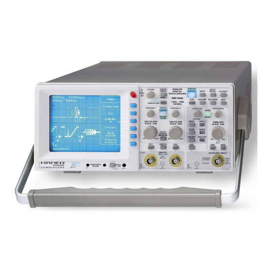
Summary of Contents for Hameg HM1008-2
- Page 1 99 Washington Street Melrose, MA 02176 Fax 781-665-0780 TestEquipmentDepot.com ® 1 0 0 M H z C o m b i S c o p e H M 1 0 0 8 - 2 Manual English...
-
Page 2: General Information Regarding The Ce Marking
HAMEG instruments fulfi ll the regulations of the EMC directive. The conformity test made by HAMEG is based on the actual generic- and 4. RF immunity of oscilloscopes. product standards. In cases where different limit values are applicable, HAMEG applies the severer standard. -
Page 3: Table Of Contents
C o n t e n t s General information regarding the CE marking AUTOSET ® 100 MHz CombiScope HM1008-2 Component tester Specifi cations CombiScope Digital operation Important hints Digital operating modes List of symbols used: Memory resolution Positioning the instrument... - Page 4 H M 1 0 0 8 - 2 ® 1 0 0 M H z C o m b i S c o p e H M 1 0 0 8 - 2 1 GSa/s Real Time Sampling, 10 GSa/s Random Sampling Either PAL or NTSC: Line triggering with line counter 1 MPt memory per channel Memory...
-
Page 5: 100 Mhz Combiscope Hm1008-2
Variable time base A/B: cont. 1:2.5 Hold Off time: var. 1:10 (LED-Indication) ® 100 MHz CombiScope HM1008-2 Bandwidth X-Amplifier: 0 - 3 MHz (-3 dB) Valid at 23 °C after a 30 minute warm-up period X Y phase shift ‹ 3°: ‹ 220 kHz... -
Page 6: Important Hints
PUOPF INPUTS PUkTKl 15pF PUkTKl 15pF 400 Vp HAMEG 400 Vp PUOPFGkT C O M B I S C O P E PUkT Important hints Please check the instrument for mechanical damage or loose parts immediately after unpacking. In case of damage we advise to contact the sender. -
Page 7: Proper Operation
Warranty and repair conforming to the minimum standards of post, rail or trans- port fi rm) HAMEG instruments are subjected to a rigorous quality control. Proper operation Prior to shipment each instrument will be burnt in for 10 hours. Intermittent operation will produce nearly all early failures. -
Page 8: Front Panel Elements - Brief Description
F r o n t P a n e l E l e m e n t s – B r i e f D e s c r i p t i o n VOLTS/DIV-SCALE-VAR (knob) Front Panel Elements – Brief Description Channel 2 Y defl... - Page 9 ANALOG ANALOG SAVE/ FOCUS INTENS POWER POWER DIGITAL MATH RECALL AUTOSET TRACE DIGITAL OSCILLOSCOPE MENU HM1008-2 RUN / STOP ACQUIRE SETTINGS HELP · CURSOR 1 GSa 1 MB MEASURE 100 MHz CH 1/2 HORIZONTAL POSITION 1 POSITION 2 LEVEL A/B...
-
Page 10: Basic Signal Measurement
Values of a sine wave signal should be kept in mind. The oscilloscope HM1008-2 can display all repetitive signals with a fundamental repetition frequency of at least 100 MHz. The frequency response is 0 to 100 MHz (-3 dB). The vertical amplifi... -
Page 11: Dc And Ac Components Of An Input Signal
(3.5 ns with the HM1008-2), t is the rise time of the probe, e.g. peak 2 ns. If the signal’s rise time is > 34 ns, the rise times of scope and probe may be neglected. -
Page 12: First Time Operation And Initial Adjustments
At the scope input a feed through 50 Ω-termination Use the red POWER pushbutton to turn the scope on. Several will be required. HAMEG offers a HZ22 termination. If proper displays will light up. The scope will then assume the set up terminations are not used, sizeable pulse aberrations will re- selected before it was turned off. -
Page 13: Mhz Adjustment
Remark: Any reference to ”both channels“ always refers to channels 1 and 2. The HAMEG probes feature additional adjustments in the compensation box which allow you to optimise their hf be- Usually oscilloscopes are used in the Yt mode. In analog mode haviour. -
Page 14: Xy Operation
O p e r a t i n g m o d e s o f t h e v e r t i c a l a m p l i f i e r sin ϕ = — may result as the input range of one or both amplifi... -
Page 15: Measurement Of Amplitude Modulation
T r i g g e r i n g a n d t i m e b a s e centre, thus overdriving the inputs resulting in sharper zero Reading a and b off the screen the modulation degree will crossings. -
Page 16: Normal Trigger Mode (See Menu Mode)
T r i g g e r i n g a n d t i m e b a s e circuit will wait for a new trigger, consequently the auto trigger coupling will be used unless ac coupling was selected before. circuit will start the time base irrespective of the signal. -
Page 17: Line Sync Pulse Triggering
T r i g g e r i n g a n d t i m e b a s e mode should be chosen. It may also be necessary to turn the an arrow pointing upwards will indicate the trigger time posi- readout off. -
Page 18: Time Base B (2Nd Time Base). Delaying, Delayed Sweep. Analog Mode
T r i g g e r i n g a n d t i m e b a s e of 10:1. Manipulation of the hold off time and thus of the time for mode the signal itself will be seen on the screen in real time, a complete sweep period from start to start can be useful e.g. -
Page 19: Autoset
C o m p o n e n t T e s t e r AUTOSET Component Tester For specific information consult ”Controls and Readout“ Specifi c information can be found in ”Controls and Readout“ un- AUTOSET der COMPONENT/PROBE and COMPONENT TESTER The following description is valid for both analog and digital The scope has a built in component tester. - Page 20 C o m p o n e n t T e s t e r component is not legible at least it is possible to see whether it is a npn or pnp transistor or which end of a diode is the cathode. Please note that reversing the test leads will also invert the picture, i.e.
-
Page 21: Combiscope
Gaussian curve, this means in practice that also process and display the signals. The HM1008-2 is a 150 MHz frequencies far beyond the –3 dB frequency will be shown, ®... -
Page 22: Digital Operation
Signals with a repetition rate lower than the rep The foregoing explains why it is HAMEG policy to offer Combi- rate of the automatic triggering can not properly trigger so the scopes rather than pure digital oscilloscopes which combine resulting display will be untriggered. -
Page 23: Memory Depth
C o m b i S c o b e Display of aliases Horizontal resolution: A maximum of 4 simultaneous signal displays may be shown on the screen. Each signal display will consist of 2048 points As explained the maximum sampling rate must be reduced for (bytes). -
Page 24: Data Transfer
STOP If the safety rules are disregarded any damage to HAMEG products will void the warranty. Neither will HAMEG take any responsibility for damages to people or equipment of other makes. -
Page 25: General Information Concerning Menu
G e n e r a l i n f o r m a t i o n c o n c e r n i n g M E N U POWER POWER Pushbutton CH I MENU Menu Title AC/DC/50 Ω... -
Page 26: Controls And Readout
B-Int.: Intensity of the signal as displayed by time base B heater has elapsed, the HAMEG logo, the instrument type and Zoom-Int.: Intensity of the signal expanded by Zoom the version number are displayed. If prior to switching off the RO Int.:... - Page 27 C o n t r o l s a n d R e a d o u t CURSOR MEASURE (pushbutton) 4.2.1.3 ” ° ” (degree), measurement of degrees The distance between the long CURSOR lines is equal to 360 On condition the cursors have been switched off, pressing the degrees and must be exactly as long as a signal period.
- Page 28 FOCUS INTENS POWER POWER DIGITAL MATH RECALL AUTOSET TRACE DIGITAL OSCILLOSCOPE MENU HM1008-2 RUN / STOP ACQUIRE SETTINGS HELP · CURSOR 1 GSa 1 MB MEASURE 100 MHz selected. The time base speeds selected will not be affected processing of current channel 1 and 2 signals. The results may...
- Page 29 C o n t r o l s a n d R e a d o u t After MA the next step causes an arrow symbol to be displayed A trigger will start a new acquisition which will overwrite the in the “Mathematics Edit“...
- Page 30 FOCUS INTENS POWER POWER DIGITAL MATH RECALL AUTOSET TRACE DIGITAL OSCILLOSCOPE MENU HM1008-2 RUN / STOP ACQUIRE SETTINGS HELP · CURSOR 1 GSa 1 MB MEASURE 100 MHz averaging will take. Averaging is a means to increase the ac- The maximum gap size is 0.25 s between the samples at a time curacy in spite of the 8 bit converters, it is an exchange of time base setting of 50 s/cm.
- Page 31 9.2.1 Reference Save 10.2.3 Quick Start On Off leads to the following 3 submenus: In off, the HAMEG logo, the type and the version number will not be shown, the instrument will be ready immediately. 9.2.1.1 Source (Reference) The “Source“ from which the signal - to be stored in a reference 10.2.4 Menu Off time...
- Page 32 SAVE/ FOCUS INTENS POWER POWER DIGITAL MATH RECALL AUTOSET TRACE DIGITAL OSCILLOSCOPE MENU HM1008-2 RUN / STOP ACQUIRE SETTINGS HELP · CURSOR 1 GSa 1 MB MEASURE 100 MHz HELP 10.4.3 Optimum display In this display mode, so called “Alias“ signal displays can be avoided.
- Page 33 C o n t r o l s a n d R e a d o u t and in the lower sector in the “Mathematics“ menu a signal SOR–MA/REF–ZOOM-pushbutton and the menu item acti- source is selected instead of “Display Off“. vated.
- Page 34 C o n t r o l s a n d R e a d o u t Note: between 5 mm (0.5 div.) and 8 cm (8 div.). Signal display heights The function Cur. Track (cursor tracking) is only >...
- Page 35 C o n t r o l s a n d R e a d o u t setting (sampling rate) must enable the display of minimum Dependent on the mode, different measurements are offered one signal period; in case of complex signals this is regarding in this menu, all relating to the trigger signal.
- Page 36 C o n t r o l s a n d R e a d o u t 18.2 Respect sing ”Slope“ will allow trigger on any signal shape. For video signals select ”Video“ and press the FILTER pushbutton 18.2.1 “Respect Tr“ indicates that the trigger signal is used for order to find a choice of special trigger modes for composite measurement.
- Page 37 C o n t r o l s a n d R e a d o u t FILTER pushbutton was depressed. For further information 21.2.1 Frame, Line. see ”Trigger coupling“ (Menu ”FILTER“) under the heading Depending on the setting chosen, triggering will be on frame ”Triggering and time bases“...
- Page 38 C o n t r o l s a n d R e a d o u t X-POS DELAY (pushbutton) 22.1 Edge/VideoTrigger no function in FFT mode 22.1.1 CH1 Conditions: Analog or digital mode, ”Edge“ or ”Video“ selected. This pushbutton allows you to change the function of the HO- CH1 will then be the trigger source, no matter whether it is RIZONTAL knob displayed or not.
- Page 39 POWER C o n t r o l s a n d R e a d o u t CH 1/2 HORIZONTAL POSITION 1 POSITION 2 LEVEL A/B X-POS CURSOR FFT- Marker MA/REF DELAY ZOOM TRIGGER MODE TRIG ’d VOLTS / DIV VOLTS / DIV TIME / DIV ·...
- Page 40 C o n t r o l s a n d R e a d o u t displays will be visible. With ”Zoom only“ only the expanded displayable frequency (f ) results. In accordance with the display will show up. Nyquist-Shannon sampling theorem, the highest frequency to displayed must be 2 * f .
- Page 41 POWER C o n t r o l s a n d R e a d o u t CH 1/2 HORIZONTAL POSITION 1 POSITION 2 LEVEL A/B X-POS CURSOR FFT- Marker MA/REF DELAY ZOOM TRIGGER MODE TRIG ’d VOLTS / DIV VOLTS / DIV TIME / DIV ·...
- Page 42 This pushbutton opens the ”CH1“ menu which contains the following options referring to CH1 and the signal on CH1. 31.4.1 If a HAMEG probe with automatic identifi cation is connec- ted, the readout shows “Probe“ in normal intensity and below 31.1. AC DC the dividing factor (e.g.
- Page 43 C o n t r o l s a n d R e a d o u t VOLTS/DIV–SCALE–VAR knob CH1 serves as variable control both are measured simultaneously. Hence no channel switching that allowes change of the defl ection coeffi cient continuously over is necessary and no information pertaining to it is shown.
- Page 44 Yt mode. In XY analog mode the limi- tation affects only CH2. 33.4.1 If a HAMEG probe with automatic identifi cation is connec- ted, the readout shows “Probe“ in normal intensity and below the dividing factor (e.g. *10).
- Page 45 C o n t r o l s a n d R e a d o u t INPUT CH2 (BNC connector) After pressing the function key, the required “window“ function (Hamming, Hanning, Blackman, Rectangle) can be determined This is the CH2 signal input connector. It is a Y input in Yt and by the INTENS knob .
- Page 46 C o n t r o l s a n d R e a d o u t CH 1 CH 2 VERT/XY CH 1 CH 2 INPUTS AUXILIARY INPUT 1MΩII15pF X-INP TRIGGER 1MΩ II 400 Vp EXTERN 15pF Z-INPUT 100 Vp CAT I CAT I...
- Page 47 C o n t r o l s a n d R e a d o u t 1 : 1 / 10 / 100 CH I: 500 mV PROBE COMP . Stick TESTER C O M B I S C O P E are displayed.
Need help?
Do you have a question about the HM1008-2 and is the answer not in the manual?
Questions and answers