
Related Manuals for Elba C 96 DF


Summary of Contents for Elba C 96 DF
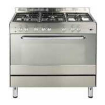
- Page 1 DUAL FUEL COOKER C 96 DF Instruction for the use - Installation advice KEEP IN A SAFE PLACE...
- Page 2 Dear Customer, IMPORTANT INSTRUCTIONS AND ADVICE FOR THE USE OF Thank you for having purchased and ELECTRICAL APPLIANCES given your preference to our product. The safety precautions and The use of any electrical appliance recommendations reported below are requires the compliance with some basic for your own safety and that of others.
-
Page 3: Important Precautions And Recommendations
IMPORTANT PRECAUTIONS WARNING When correctly installed, your product AND RECOMMENDATIONS meets all safety requirements laid down for this type of product category. After having unpacked the appliance, However special care should be taken check to ensure that it is not damaged around the rear or the underneath of and that the oven door closes correctly. -
Page 4: Cooking Hob
1 - COOKING HOB Fig. 1.1 1. Auxiliary burner (A) 1,00 kW 2. Semi-rapid burner (SR) 1,90 kW 3. Rapid burner (R) 3,15 kW 4. Double-ring burner (DR) 3,45 kW... -
Page 5: Control Panel
2 - CONTROL PANEL Fig. 2.1 CONTROL PANEL - Controls description 1. Conventional oven switch knob 2. Conventional oven temperature knob 3. 120’ cut-off timer control knob 4. Front left burner control knob 5. Rear left burner control knob 6. Central burner control knob 7. -
Page 6: Use Of Cooking Hob
3 - USE OF COOKING HOB GAS BURNERS Each burner is controlled by a gas tap assuring the opening and the closing of the gas supply. Make the lever of the knob match with the symbol printed on the control panel to obtain: - symbol : off... -
Page 7: Choice Of The Burner
CHOICE OF THE BURNER ELECTRIC SPARK IGNITION On the control panel, near every knob, To light the burner you have to rotate there is a diagram that indicates which the knob (fig. 3.2) corresponding to the burner is controlled by that knob. specific burner to the maximum flame The suitable burner must be chosen position (large flame symbol) and press... - Page 8 SPECIAL GRIDS FOR WOKS (fig. 3.5a - 3.5b) The special grid for woks rests on the grid of the double-crown burner. Warning: – Using woks without this special grid could seriously damage the burner. 3.5a - 3.5b – Do not use this grid with flat bottomed pans (Figs. IMPORTANT: The special grille for wok pans (fig.
-
Page 9: General Features
4 - ELECTRICAL CONVECTION OVEN NOTE: Attention: the oven door becomes Upon first use, it is advisable to operate very hot during operation. the oven at the maximum temperature Keep children away. (thermostat knob on position 250°C) for 60 minutes in the position and for another 15 minutes in the mode in... -
Page 10: Thermostat Knob
THERMOSTAT KNOB (Fig. 4.2) LOWER HEATING ELEMENT This only sets the cooking temperature and does not switch the oven on. In this position only the lower element is Rotate clockwise until the required switched on. Heat is distributed by nat- temperature is reached (from 50 to 250°... -
Page 11: Use Of The Grill
USE OF THE GRILL COOKING EXAMPLES Temperatures times Leave to warm up for approximately 5 approximate as they vary depending on minutes with the door closed. the quality and amount of food. Place the food inside positioning the rack as near as possible to the grill. Remember to use ovenproof dishes and Insert the drip pan under the rack to col- to adjust the oven temperature during... - Page 12 5 - 120’ CUT-OFF TIMER TIMER (Fig. 5.1) The timer runs the electric oven for a preset time. 1) Starting up. After setting the electric oven selector knob rotate the timer knob clockwise until you reach the required cooking time (max 120 minutes). Once this time has elapsed, the timer will return to the “0”...
-
Page 13: Cleaning And Maintenance
6 - CLEANING AND MAINTENANCE IMPORTANT NOTES Installation, and any demonstration, information or adjustments are not included in the warranty. The cooker must be installed by a qualified person in accordance with the Gas Safety (Installation and Use) (Amendment) Regulations 1990 and the relevant building/l.E.E Regulations. -
Page 14: Enamelled Parts
ENAMELLED PARTS BURNERS They can be removed and washed with All the enamelled parts must be cleaned soapy water only. with a sponge and soapy water or other They will remain always perfect if cleaned non-abrasive products. with products used for silverware. Dry preferably with a soft cloth. -
Page 15: Replacing The Oven Light Bulb
FLEXIBLE TUBE ASSEMBLY AND DISMANTLING OF THE SIDE RUNNER FRAMES From time to time, check the flexible tube connecting the gas supply to the – Fit the side runner frames into the cooker. holes on the side walls inside the It must be always in perfect condition;... -
Page 16: Oven Floor
Fig. 6.4 OVEN FLOOR OVEN DOOR The oven floor “F” (fig. 6.5) can be easily The internal glass panel can be easily removed to facilitate cleaning. removed for cleaning by unscrewing the Remember to replace the floor correctly 4 retaining screws (Fig. 6.4) afterwards. -
Page 17: Removing The Oven Door
REMOVING THE OVEN DOOR The oven door can easily be removed as Fig. 6.6A follows: – Open the door to the full extent (fig. 6.6A). – Attach the retaining rings to the hooks on the left and right hinges (fig. 6.6B). –... -
Page 18: Advice For The Installer
Advice for the installer IMPORTANT – Cooker installation, regulation and conversion to other gas types must only be carried out by QUALIFIED TECHNICIANS. Failure to observe this rule will invalidate the war- ranty. – The electrical mains outlet, if located behind the cooker, must not be higher than 18 cm above the floor level. -
Page 19: Installation
7 - INSTALLATION This cooker has type X overheating protection so that it can be installed next to a cabinet. If the cooker is installed adjacent to furniture which is higher than the gas hob cooktop, a gap of at least 200 mm must be left between the side of the cooker and the furniture. The furniture walls adjacent to the cooker must be made of material resistant to heat. -
Page 20: Fitting The Adjustable Feet
Fig. 7.3 Fig. 7.2 FITTING THE ADJUSTABLE FEET The adjustable feet must be fitted to the base of the cooker before use. Rest the rear of the cooker an a piece of the polystyrene packaging exposing the base for the fitting of the feet. LEVELLING THE COOKER The cooker may be levelled by screwing the lower ends of the... -
Page 21: Moving The Cooker
MOVING THE COOKER WARNING When raising cooker to upright posi- tion always ensure two people carry out this manoeuvre to prevent dam- age to the adjustable feet (fig. 7.5). WARNING Be carefull: do not lift the cooker by the door handle when raising to the upright position (fig. -
Page 22: Provision For Ventilation
PROVISION FOR VENTILATION The room containing the cooker should have an air supply in accordance with BS.5540: Part 2: 1989. All rooms require an openable window or equivalent while some rooms require a permanent vent in addition to the openable window. The cooker should not be installed in a bed-sitting room, of volume less than 21 m Where a DOMESTIC COOKER is installed in a room or internal space, that room or internal space shall be provided with a permanent opening which communicates directly... -
Page 23: Gas Section
8 - GAS SECTION GAS INSTALLATION GAS CONNECTION IMPORTANT NOTE The installation of the cooker to Natural Gas or LP Gas must be carried out by a This appliance is supplied for use on qualified gas engineer. Installers shall NATURAL GAS only and cannot be take due account of the provisions of the used on any other gas without modifica- relevant British Standards Code of... - Page 24 GAS CONNECTION The gas supply must use the nearest gas inlet pipe which is located at the left or the right hand side at the rear of the appliance (fig. 8.1). The unused end inlet pipe must be closed with the plug interposing the gasket. Flexible hoses can be used where the sited ambient temperature of the hose does not exceed 70°C.
- Page 25 To avoid damage to the appliance gas rail inlet pipe the fittings should be tightened using two suitable spanners (fig. 8.2). After connection to the mains gas supply the couplings should be checked for gas soundness/tightness as per current regulations for the gas type being used.
-
Page 26: Conversion To Lpg
CONVERSION TO LPG 1 - Injectors replacement of top burners The injectors can be obtained from the “Service Centre”. To replace the injectors it is necessary to lift the hobtop and proceed as follows: – Remove pan-supports and burners from the hobtop. –... - Page 27 2 - Adjusting of primary air of the top burners By releasing the screw “M”, reset the air adjuster “K” according to the instructions see “Table for the choice of the injectors”, where the distance between injector and air adjuster is recommended (in mm).
-
Page 28: Lubrication Of The Gas Taps
TABLE FOR THE CHOICE OF THE INJECTORS Cat: 2H3+ G 30 - 28-30 mbar G 20 Reduced Nominal BURNERS G 31 - 37 mbar 20 mbar Power Power Ø injector Ø injector Ring opening Ring opening [kW] [kW] [mm] [mm] [1/100 mm] [1/100 mm] 1,00... -
Page 29: Electrical Section
9 - ELECTRICAL SECTION N.B. For connection to the mains, do not use adapters, reducers or IMPORTANT: The cooker must be branching devices as they can cause installed in accordance with the overheating and burning. manufacturer’s instructions. Incorrect installation, for which the If the installation requires alterations to manufacturer accepts no responsi- the domestic electrical system or if the... - Page 30 ELECTRICAL FEEDER CABLE FEEDER CABLE SECTION CONNECTION TYPE H05RR-F To connect the supply cable: - Remove the screws securing the 230 V 3 x 1,5 mm cover “A” on the rear of the cooker (fig. 9.1). - Feed the supply cable through the cable clamp “D”.
-
Page 31: After Sales Service
AFTER SALES SERVICE If you require After Sales Service contact the MASTERCARE Domestic Appliance Helpline Telephone 08701 565550. Ser. Nr. IMPORTANT INFORMATION FOR CORRECT DISPOSAL OF THE PRODUCT IN ACCORDANCE WITH EC DIRECTIVE 2002/96/EC. At the end of its working life, the product must not be disposed of as urban waste. It must be taken to a special local authority differentiated waste collection centre or to a dealer providing this service. - Page 32 Cod. 1102463 - ß5...
Need help?
Do you have a question about the C 96 DF and is the answer not in the manual?
Questions and answers