Table of Contents
Advertisement
Advertisement
Table of Contents

Related Manuals for First Alert DVRA0405


Summary of Contents for First Alert DVRA0405
-
Page 1: Security System
SECURITY SYSTEM USER’S MANUAL Model DVRA0405/DVRA0805/DVRA0810/DVRA1610... -
Page 2: Introduction
© 2012 BRK Brands, Inc. All rights reserved. Distributed by BRK Brands, Inc., Aurora, Illinois 60504. BRK Brands, Inc. is a subsidiary of Jarden Corporation (NYSE: JAH). First Alert® and SmartBridge™ are registered trademarks of the First Alert Trust. Due to continuing product develop- ment, the product inside the packaging may look slightly different than the one on the package. - Page 3 INTRODUCTION KEY PRODUCT FEATURES Main Description Eight channel H.264 digital video recorder with Internet remote surveillance, motion detection, PTZ and alarm control suitable for applications such as high-end residential - new or remodel, light commercial, small business/retail, small warehouse or small grocery. Product Features • Auto IP connection capability • H.264 Compression &...
-
Page 4: Table Of Contents
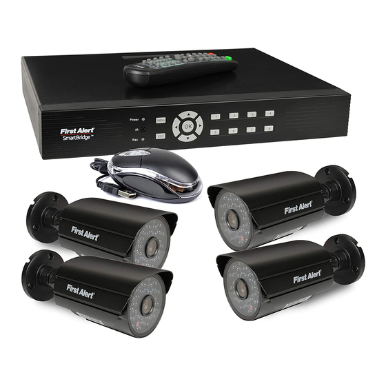
INTRODUCTION TABLE OF CONTENTS ection eScription Introduction Safety Product Overview What is in the Box DVR Controls Front Panel Back Panel Remote Control Mouse and Virtual Keypad Camera Power Connections Connecting Devices Initial Setup - System Operation System Start Up Power On/Off Main Menu Access (Quick Access Menu) Password Setup and User Permissions... -
Page 5: Introduction
INTRODUCTION TABLE OF CONTENTS ection eScription Advanced Operation Alarm 22-23 Alarm In Setup 22-23 System Info and System Update System Maintain Upgrade Firmware PTZ Setup and Control 25-26 Step 1: Connect your PTZ Camera to this DVR Step 2: Configure PTZ Communication Settings Step 3: Configure the Operation and Control of your PTZ Camera(s) Step 4: Configure the CRUISE SETTING of your PTZ Camera Remote Access... -
Page 6: Safety
FCC Declaration of Conformity for devices with the FCC logo. Responsible Party: First Alert / BRK Brands, Inc., 3901 Liberty Street Rd., Aurora, IL. 60504- 8122. Telephone: (630) 851 - 7330. Product / Model: DVRA0405, DVRA0805, DVRA0810, and DVRA1610. We, First Alert / BRK Brands, Inc. declare under our sole responsibility that the device to which this declaration relates: Complies with Part 15 of the FCC Rules. -
Page 7: Product Overview
© 2012 BRK Brands, Inc. All rights reserved. Distributed by BRK Brands, Inc., Aurora, Illinois 60504. BRK Brands, Inc. is a subsidiary of Jarden Corporation (NYSE: JAH). First Alert® is a registered trademark of the First Alert Trust. Due to continuing product development, the product inside the packaging may look slightly different than the one on the package. -
Page 8: Dvr Controls
PRODUCT OVERVIEW DVR CONTROLS Front Panel unction ontrol eScription (1) IR remote receiver Direct remote towards this position when using DVR Power indicator light A green light indicates power is on Record indicator light A green flashing light indicates recording Buttons 1-4(8)(16) Camera Selection Press for camera selection of channels 10-16... -
Page 9: Back Panel
PRODUCT OVERVIEW DVR CONTROLS Back Panel unction eScription Alarm 4 alarm inputs; 1 alarm output VGA Output For connecting to VGA monitor Use Lower USB port for mouse connection; Use Upper USB port for USB USB/Mouse flashdrive or backup For connecting RJ45 ethernet cable to PC or router RS485 For connecting PTZ cameras Power Switch... -
Page 10: Remote Control
PRODUCT OVERVIEW REMOTE CONTROL Remote Control Remote Control Operation The remote control is the secondary input device for navigating the system’s interface. In device operation, the MENU key has the same function as “left click” of the mouse. unction eScription Power Click power for about 3-5 seconds to shut down the DVR. -
Page 11: Mouse And Virtual Keypad
PRODUCT OVERVIEW MOUSE AND VIRTUAL KEYPAD Mouse Controls Mouse Operation with this DVR The mouse is the primary input device for navigating system menus. NOTE: Unless otherwise noted, all system functions described in this manual are achieved through mouse input. To use a mouse with the system: Connect a USB mouse to the USB MOUSE port on back panel of the system. -
Page 12: Camera Power Connections
Select the position for the camera and secure the camera stand. Screw the camera onto the stand. Adjust camera to the proper view angle. Make sure the lens is upright relative to the subject. Tighten the thumb bolt. First Alert cameras can be either ceiling or wall mounted by simply reversing the camera stand mounting. -
Page 13: Initial Setup System Operation
INITIAL SETUP SYSTEM OPERATION System Start Up Power On/Off To power the system On/Off, connect the power cable to the DC 12V port on the rear panel. Flip the toggle switch on in the back of the DVR. At startup, the system performs a basic system check and runs an initial loading sequence. -
Page 14: Main Menu Access (Quick Access Menu)
• For security reasons, it is highly recommended to enable pass- words on your system. If you enable passwords, select a 1-10 alpha-numeric USER password. • If you forgot your password, please contact First Alert Consumer Affairs @ 1-800-323-9005. A notarized letter will be needed for any password override. -
Page 15: Language
INITIAL SETUP SYSTEM OPERATION To Add a LOCAL or NeTWORK USeR To add or edit a new Local or Network User, from the Setup Menu, choose SYSTEM and then USER. Click ok to access this menu. 1. Choose Local or Network User Group. 2. -
Page 16: Camera Display Setup
INITIAL SETUP SYSTEM OPERATION Video Display Live View Set Up To customize the video display on your monitor, use the DISPLAY screen. Access the DISPLAY screen from the SETUP menu, by selecting SETTING from the drop down menu, and then Display. The following screen appears. Channel: Select the channel for setup. -
Page 17: Date And Time
INITIAL SETUP SYSTEM OPERATION system settings. The settings range from 100 (clear) to 255 (opaque) Video Layout The Video Layout screen allows you to customize layout of the channels to view on the monitor. Right click on home screen to select layout. Split Screen Options: Full Screen - Allows current channel to be displayed at full screen. -
Page 18: Basic Operation
BASIC OPERATION RECORDING Recording Manual Record There are multiple ways to set a channel to Record. The most simple way is to record all the time. Right click the mouse to reach the drop down menu. From there select RECORD by highlighting and clicking the mouse. -
Page 19: Motion Detection Setup
BASIC OPERATION RECORDING CCTV Resolution CCTV Resolutions CCTV resolution is measured in vertical and horizontal pixel dimensions and typically D1: 704 x 480 limited by the capabilities of both the camera and the recorder that you are using for your CCTV surveillance installation. -
Page 20: Playback
BASIC OPERATION PLAYBACK SnapShot Picture Management Live SnapShot Executing a snapshot is easy. To take a snapshot 1. Double click in camera view to see a full screen view of the camera channel. 2. Right click the mouse to access the quick menu drop down 3. -
Page 21: Playback And Record Search
BASIC OPERATION PLAYBACK flash drives, with capacities from 256 MB to 4 GB. Video Playback Recorded video is accessed through the Search Recording screen. To access the recordings, right click the mouse to access the quick menu drop down. Select PLAYBACK. The SEARCH RECORDING screen will appear on screen. -
Page 22: Advanced Operation
ADVANCED OPERATION ALARM Alarm Alarm In: Software Setting: Main menu <Setting> <Device> <Alarm In> Use the Alarm In feature to configure alarm settings. To access the Alarm In feature, right click the mouse to access the quick access menu under setting. - Page 23 ADVANCED OPERATION ALARM Alarm Inputs: Alarm inputs are devices or switches that activate when a door, window, cabinet etc. is opened or accessed. For example, you might want to only have the camera record when someone opens a tool cabinet or when a door opens vs. recording when motion occurs around those areas.
-
Page 24: System Info And System Update
Update Firmware updates may be available periodically. They will be made available for download onto a USB disk from the First Alert as needed. Please see FirstAlert.com/ Home Security/Security Cameras. Place a USB device into the slot on the rear panel of the DVR. Make sure it is formatted and has enough space to accommodate the firmware. -
Page 25: Ptz Setup And Control
ADVANCED OPERATION Pan tilt zoom...PTZ Pan/Tilt/Zoom (PTZ) Setup: Note: Consult the instruction manual of your PTZ camera for complete information about your camera, including protocol, baud rate and parity settings before beginning setup. Enter these settings in the DVR. STEP 1: Connect your PTZ Camera to this DVR Connect a PTZ camera to the BNC and DC power cables. -
Page 26: Step 4: Configure The Cruise Setting Of Your Ptz Camera
ADVANCED OPERATIONS PTZ SETUP Step 3: Configure the operation & control of your PTZ camera(s): In live view, double click on the channel with the connected PTZ camera to open to full screen view. This selects the channel to configure and control. 1. -
Page 27: Remote Access
REMOTE ACCESS NETWORK SETUP Network Setup for Remote Access Network Setup for Remote Access Your Auto ID system is capable of connecting to a local area network (LAN) to view remotely, without the use of port forwarding. Please follow the steps below. Right click and select setting. - Page 28 REMOTE ACCESS NETWORK SETUP wizard is finished. Double click the icon to run the Smartbridge Software. Page 28...
- Page 29 REMOTE ACCESS NETWORK SETUP The connect tab is for connecting to one SmartBridge DVR only. Use the advanced Tab when connecting to multiple Smartbridge DVR’s at once. (Group). See adding groups section. • Click Port to enter the port settings. This is to assign a router port that is open.
- Page 30 REMOTE ACCESS NETWORK SETUP You are now connected to the SmartBridge DVR remotely. All cameras that are connected to your SmartBridge system should now be shown on the Smartbridge software screen. Page 30...
- Page 31 REMOTE ACCESS NETWORK SETUP Press this button to connect all cameras connected to the Auto ID system. Also, Right click on a camera source screen and select connect. Press this button to disconnect all cameras connected to the Auto ID system. Also, Right click on a camera source screen and select disconnect.
-
Page 32: Record External
REMOTE ACCESS RECORD EXTERNAL RECORD EXTERNAL You are able to record using the remote software simultaneously to recording on the Smartbridge DVR system. In order to record using the Smartbridge remote software, you will need an 80 GB minimum external hard drive formatted to FAT32. Plug an external hard drive into your computer. -
Page 33: Playback External
REMOTE ACCESS PLAYBACK EXTERNAL Select a Channel, Click to capture a still image of a camera in view. This image will be saved to the external hard drive. PLAYBACK EXTERNAL Select Playback external to play back recorded files. 16:9 All files available on the External hard drive can be played back on the Smartbridge Software. - Page 34 REMOTE ACCESS PLAYBACK EXTERNAL Opens a saved .sv5 file to play. Shows One Screen Plays a recorded video Shows four channels in four screens Stops a recorded video during playback Click repeatedly to Fast Forward at different Shows nine channels in nine screens speeds of a recorded video Click repeatedly to play a Slow forward speed of a recording.
-
Page 35: Settings
REMOTE ACCESS SETTINGS Settings Select to adjust specific settings for your Smartbridge DVR. (See recording external for Storage Tab information) Select the Advanced Tab. Check the Place system always on top box to place the Smartbridge on top of all other software within the operating system. Check the Disabled Ctrl-Alt-Del when system is locked box to disable the use of Ctrl-Alt- Del when you lock the system. -
Page 36: Advanced Settings
REMOTE ACCESS ADVANCED SETTINGS Advanced Settings Select to open the advanced settings options for your Smartbridge DVR • Switch User (Feature enabled in advanced mode only): Switches between users (see setting up groups) • TV Mode: Select TV mode to place all connected channels to share the full screen. -
Page 37: Pan Tilt Zoom
REMOTE ACCESS PAN TILT ZOOM Pan Tilt Zoom If you have pan tilt zoom cameras installed, you are able to control the pan tilt zoom cameras remotely with the Smartbridge Software. Press to move PTZ camera up Press to move PTZ camera left Press to move PTZ camera down Press to move PTZ camera right Iris... -
Page 38: Setting Up Groups
REMOTE ACCESS SETTING UP GROUPS To add a group, Select settings To add a group, select the Video Source/group Tab • Select add group. • Type the name of the group in the current group box. • Select Modify to save the new group. o Enter the username and password o Enter an Alias name for the group. -
Page 39: Remote Configuration
REMOTE CONFIGURATION CAMERA SETTINGS Web service - currently not function Mobile service - to enable mobile browsing Port - this is the web port which should always be at 80 Quality- selects the quality of the streaming video Channel - select channel you would like to apply settings to Device ID - shows your DVR ID number FPS - frames per second. -
Page 40: Remote Configuration
REMOTE CONFIGURATION CAMERA SETTINGS Device Logs Screen PTZ Options Screen Page 40... -
Page 41: Appendix
APPENDIX HARD DRIVE Hard Drive Removal and Installation HDD Installation To replace the hard drive in the DVR: CAUTION: TO REDUCE THE RISK OF ELECTRIC SHOCK. UNPLUG ALL POWER SOURCES, INCLUDING CAMERAS FROM THE DVR BEFORE REMOVING COVER. FAILURE TO DO SO CAN RESULT IN DAMAGE TO THE DVR OR ITS COMPONENTS AS WELL AS INJURY OR DEATH Remove screws securing the cover of the DVR and remove cover. -
Page 42: Specifications
APPENDIX SPECIFICATIONS Technical Specifications Item Device Parameter Specification Language English/ Spanish/ French System 16 Bit Graphic menu (OSD Menu) Password User password, Administrator password Video in 4/8/16 channel composite video input 1.0Vp-p, impedance 75Ω, BNC Video out 1 VGA, 1 BNC (CVBS) Video Video display 4/8/16 channel: 1/4/8/9... - Page 43 APPENDIX Tech Services: 800-323-9005 If your problem is not listed below, please call our toll-free number for more support. Question: Why does DVR not work after starting? Why did the DVR stop working? Answer: • Check that the power adapter is plugged into the DVR properly •...
- Page 44 APPENDIX Question: Why is there no audio when playing back? Answer: • Check to see that the audio settings for the channels are correct. • Audio is off in record menu Question: Why is my system time not correct? Answer: •...
-
Page 45: Troubleshooting
APPENDIX TROUBLESHOOTING Troubleshooting Error Possible Cause Solutions • Confirm that all cables are connected correctly • Confirm that the power adapter is securely connected to the back Cable from power adapter is loose or is unplugged of the unit • Confirm that the system is powered on (LED indicators on the System is not receiving front should be ON) power or is not powering up... -
Page 46: Warranty
PRODUCT LIMITeD WARRANTY BRK Brands, Inc., (“BRK”) the maker of First Alert® brand products warrants that for a period of one year from the date of purchase (the “Warranty Period”), this product will be free from defects in material and workmanship. BRK, at its sole option, will repair or replace this product or any component of the product found to be defective during the Warranty Period. - Page 47 BRK Brands, Inc. ©2012 a Jarden Corporation Company (NYSE:JAH) 3901 Liberty Street Road, Aurora, IL 60504-8122 Phone: 630-851-7330 Tech Services: 800-323-9005 www.brkelectronics.com M08-0448-000...
Need help?
Do you have a question about the DVRA0405 and is the answer not in the manual?
Questions and answers