Table of Contents
Advertisement
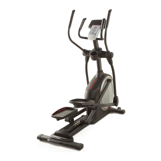
Model No. PFEVEL49716.0
Serial No.
Write the serial number in the space
above for reference.
Serial
Number
Decal
CUSTOMER SERVICE
UNITED KINGDOM
Call: 0330 123 1045
From Ireland: 053 92 36102
Website: www.iconsupport.eu
E-mail: csuk@iconeurope.com
Write:
ICON Health & Fitness, Ltd.
Unit 1D, The Gateway
Fryers Way, Silkwood Park
OSSETT
WF5 9TJ
UNITED KINGDOM
AUSTRALIA
Call: 1800 993 770
E-mail: australiacc@iconfitness.com
Write:
ICON Health & Fitness
PO Box 635
WINSTON HILLS NSW 2153
AUSTRALIA
CAUTION
Read all precautions and instruc-
tions in this manual before using
this equipment. Keep this manual
for future reference.
USER'S MANUAL
www.iconeurope.com
Advertisement
Table of Contents

Related Manuals for Pro-Form ENDURANCE 420 E


Summary of Contents for Pro-Form ENDURANCE 420 E
- Page 1 Model No. PFEVEL49716.0 Serial No. USER’S MANUAL Write the serial number in the space above for reference. Serial Number Decal CUSTOMER SERVICE UNITED KINGDOM Call: 0330 123 1045 From Ireland: 053 92 36102 Website: www.iconsupport.eu E-mail: csuk@iconeurope.com Write: ICON Health & Fitness, Ltd. Unit 1D, The Gateway Fryers Way, Silkwood Park OSSETT...
-
Page 2: Table Of Contents
TABLE OF CONTENTS WARNING DECAL PLACEMENT ............. . .2 IMPORTANT PRECAUTIONS . -
Page 3: Important Precautions
IMPORTANT PRECAUTIONS WARNING: To reduce the risk of serious injury, read all important precautions and instructions in this manual and all warnings on your elliptical before using your elliptical. ICON assumes no responsibility for personal injury or property damage sustained by or through the use of this product. -
Page 4: Before You Begin
Thank you for selecting the revolutionary PROFORM reading this manual, please see the front cover of this ® ENDURANCE 420 E elliptical. The ENDURANCE 420 manual. To help us assist you, note the product model E elliptical provides an impressive selection of features number and serial number before contacting us. -
Page 5: Part Identification Chart
PART IDENTIFICATION CHART Use the drawings below to identify the small parts needed for assembly. The number in parentheses below each drawing is the key number of the part, from the PART LIST near the end of this manual. The number following the key number is the quantity needed for assembly. -
Page 6: Assembly
ASSEMBLY • Assembly requires two persons. • In addition to the included tool(s), assembly requires the following tools: • Place all parts in a cleared area and remove the one Phillips screwdriver packing materials. Do not dispose of the packing materials until you finish all assembly steps. - Page 7 3. Press the Cover Mounts (106) on the underside of the Rear Stabilizer Cover (15) into the Rear Stabilizer (2). 4. With the help of a second person, place some of the packing materials (not shown) under the front of the Frame (1). Have the second per- son hold the Frame to prevent it from tipping while you complete this step.
- Page 8 5. Orient the Upright (4) as shown. Have a second Wire person hold the Upright near the Frame (1). See the inset drawing. Locate the wire tie in the lower end of the Upright (4). Tie the wire tie to the Main Wire (48).
- Page 9 7. Using a plastic bag to keep your fingers clean, apply some of the included grease to the Pivot Axle (35) and to two 16mm Wave Washers (54). Insert the Pivot Axle (35) through the Upright (4) and center it. Tip: It may be helpful to use a rubber mallet.
- Page 10 9. The Console (7) requires four D batteries (not included); alkaline batteries are recommended. Do not use old and new batteries together or alkaline, standard, and rechargeable batter- ies together. IMPORTANT: If the Console has been exposed to cold temperatures, allow it to warm to room temperature before insert- ing batteries.
- Page 11 11. Tip: Avoid pinching the wires. Attach the Console (7) to the Upright (4) with four M4 x 16mm Screws (101); start all the Screws, Avoid pinching and then tighten them. the wires 12. Orient the Right Pedal Arm (58) as shown. Apply grease to the axle on the Right Pedal Arm (58).
- Page 12 13. Apply a small amount of grease to one of the Pedal Arm Axles (64). Next, slide an M8 Washer (97) and an Axle Spacer (77) onto an M8 x 13mm Screw (82), and tighten the Screw a few turns into the Pedal Arm Axle (64).
- Page 13 15. Identify the Right Arm Front Cover (65) and ori- ent it as shown. Attach the Right Arm Front Cover (65) to the Right Upper Body Leg (60) with two M4 x 16mm Screws (101). Next, identify the Right Arm Rear Cover (66) and orient it as shown.
- Page 14 17. Orient the Shield Cover Cap (11) and the Shield Cover (75) as shown. First, press the tabs on the Shield Cover Cap (11) into the Left and Right Shields (73, 74). Then, press the tabs on the Shield Cover (75) into the Left and Right Shields (73, 74).
-
Page 15: How To Use The Elliptical
HOW TO USE THE ELLIPTICAL HOW TO MOVE THE ELLIPTICAL HOW TO LEVEL THE ELLIPTICAL Due to the size and weight of the elliptical, moving If the elliptical rocks it requires two persons. Stand in front of the elliptical, slightly on your hold the upright, and place one foot against one of the floor during use, wheels. - Page 16 HOW TO EXERCISE ON THE ELLIPTICAL To mount the elliptical, hold the handlebars or the Upper upper body arms and step onto the pedal that is in the Body Arms lower position. Then, step onto the other pedal. Push the pedals until they begin to move with a continuous motion.
- Page 17 CONSOLE DIAGRAM FEATURES OF THE CONSOLE The advanced console offers an array of features designed to make your workouts more effective and enjoyable. When you use the manual mode of the console, you can change the resistance of the pedals with the touch of a button.
- Page 18 HOW TO USE THE MANUAL MODE The upper display—This display will show your pedal- 1. Turn on the console. ing speed in revolutions per minute (RPM) and your Press any button or begin pedaling to turn on the power output in watts. The console.
- Page 19 To pause the console, stop pedaling. When the When your pulse is detected, your heart rate will be console is paused, the displays will pause. To shown in the upper display. For the most accurate continue your workout, simply resume pedaling. heart rate reading, hold the contacts for at least 15 seconds.
- Page 20 HOW TO USE A PRESET WORKOUT As you exercise, keep your pedaling speed within the target speed zone for the current segment by 1. Turn on the console. increasing or decreasing your pedaling speed or by increasing or decreasing the resistance of the Press any button or begin pedaling to turn on the pedals.
- Page 21 THE OPTIONAL CHEST HEART RATE MONITOR 2. Connect your smart device to the console. Whether your Follow the instructions in the iFit app to connect goal is to your smart device to the console. burn fat or to strengthen your When a connection is established, the LED on the cardiovascular console will flash blue.
- Page 22 HOW TO CONNECT YOUR HEART RATE MONITOR THE SETTINGS MODE TO THE CONSOLE The console features a settings mode that allows you The console is compatible with all BLUETOOTH Smart to select a unit of measurement for the console and to heart rate monitors.
-
Page 23: Maintenance And Troubleshooting
MAINTENANCE AND TROUBLESHOOTING MAINTENANCE Next, locate the Reed Switch (38). Turn the Pulley (19) until a Magnet (43) is aligned with the Reed Switch. Regular maintenance is important for optimal performance and to reduce wear. Inspect and properly tighten all parts each time the elliptical is used. Replace any worn parts immediately. - Page 24 HOW TO ADJUST THE DRIVE BELT See EXPLODED DRAWING C on page 31. Remove the M4 x 25mm Screws (3), the M4 x 19mm If the pedals slip while you are pedaling, even while Screws (5), and the M4 x 48mm Screw (107) from the Left and Right Shields (73, 74);...
-
Page 25: Exercise Guidelines
EXERCISE GUIDELINES Burning Fat—To burn fat effectively, you must exer- WARNING: cise at a low intensity level for a sustained period of Before beginning this time. During the first few minutes of exercise, your or any exercise program, consult your physi- body uses carbohydrate calories for energy. - Page 26 SUGGESTED STRETCHES The correct form for several basic stretches is shown at the right. Move slowly as you stretch; never bounce. 1. Toe Touch Stretch Stand with your knees bent slightly and slowly bend forward from your hips. Allow your back and shoulders to relax as you reach down toward your toes as far as possible.
-
Page 27: Part List
PART LIST Model No. PFEVEL49716.0 R0116A Key No. Qty. Description Key No. Qty. Description Frame Roller Rear Stabilizer Pedal Arm Rear Cap M4 x 25mm Screw Large Axle Cover Upright 16mm Wave Washer M4 x 19mm Screw Small Axle Cover Front Stabilizer Roller Arm Bushing Console... - Page 28 Key No. Qty. Description Key No. Qty. Description M4 x 16mm Screw Cover Mount M8 Locknut M4 x 48mm Screw M6 x 12mm Screw – Assembly Tool M10 x 122mm Screw – Grease Packet M10 Split Washer – User’s Manual Note: Specifications are subject to change without notice.
-
Page 29: Exploded Drawing
EXPLODED DRAWING A Model No. PFEVEL49716.0 R0116A... - Page 30 EXPLODED DRAWING B Model No. PFEVEL49716.0 R0116A...
- Page 31 EXPLODED DRAWING C Model No. PFEVEL49716.0 R0116A...
-
Page 32: Ordering Replacement Parts
ORDERING REPLACEMENT PARTS To order replacement parts, please see the front cover of this manual. To help us assist you, be prepared to provide the following information when contacting us: • the model number and serial number of the product (see the front cover of this manual) •...
Need help?
Do you have a question about the ENDURANCE 420 E and is the answer not in the manual?
Questions and answers