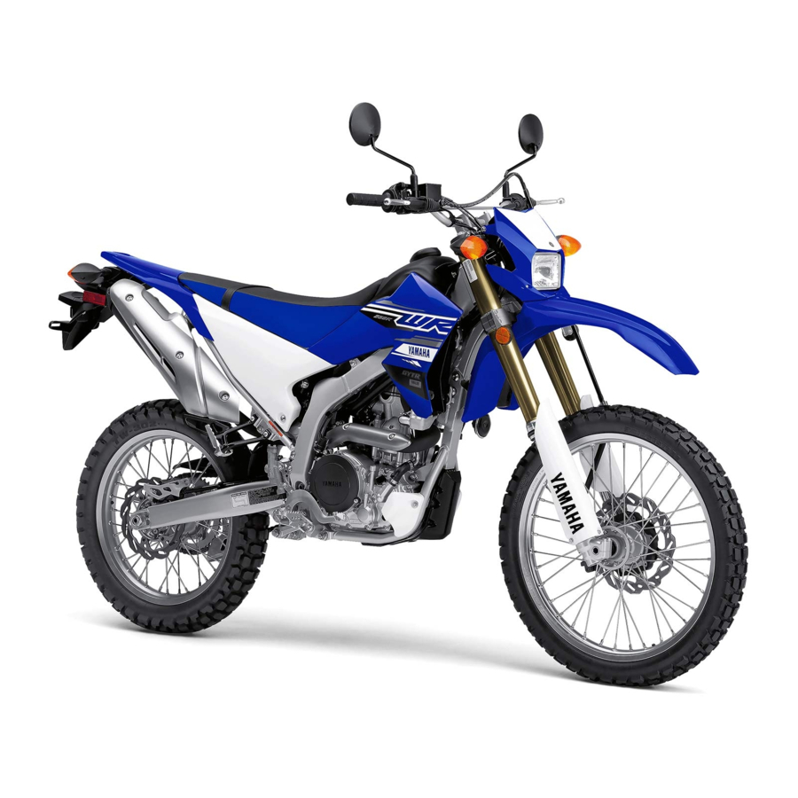
Yamaha WR250R Owner's Manual
Hide thumbs
Also See for WR250R:
- Service manual (364 pages) ,
- Owner's manual (98 pages) ,
- Owner's manual (112 pages)

Related Manuals for Yamaha WR250R


Summary of Contents for Yamaha WR250R
- Page 1 Read this manual carefully before operating this vehicle. OWNER’S MANUAL WR250R BN3-28199-E0...
- Page 2 EAU46091 Read this manual carefully before operating this vehicle. This manual should stay with this vehicle if it is sold.
- Page 3 Yamaha a reputation for dependability. Please take the time to read this manual thoroughly, so as to enjoy all advantages of your WR250R. The Owner’s Manual does not only instruct you in how to operate, inspect and maintain your motorcycle, but also in how to safeguard yourself and others from trouble and injury.
-
Page 4: Important Manual Information
Important manual information EAU10134 Particularly important information is distinguished in this manual by the following notations: This is the safety alert symbol. It is used to alert you to potential personal injury hazards. Obey all safety messages that follow this symbol to avoid possible injury or death. - Page 5 Important manual information EAU10201 WR250R OWNER’S MANUAL ©2015 by Yamaha Motor Co., Ltd. 1st edition, June 2015 All rights reserved. Any reprinting or unauthorized use without the written permission of Yamaha Motor Co., Ltd. is expressly prohibited. Printed in Japan.
-
Page 6: Table Of Contents
Table of contents Safety information ......1-1 Operation and important riding Adjusting the brake lever free points..........5-1 play..........6-23 Description ........2-1 Starting the engine ......5-1 Checking the shift pedal ....6-24 Left view .......... 2-1 Shifting ..........5-2 Brake light switches ....... - Page 7 Table of contents Replacing a turn signal light bulb ..........6-37 Replacing the license plate light bulb ..........6-37 Supporting the motorcycle..... 6-38 Front wheel........6-39 Rear wheel ........6-40 Troubleshooting......6-42 Troubleshooting charts ....6-43 Motorcycle care and storage ... 7-1 Matte color caution ......
-
Page 8: Safety Information
Safety information EAU1031C Take a training course. Beginners • Use extra caution when you are should receive training from a cer- approaching passing tified instructor. Contact an autho- through intersections, since in- Be a Responsible Owner rized motorcycle dealer to find out tersections are the most likely As the vehicle’s owner, you are respon- about the training courses nearest... - Page 9 Safety information tice riding your motorcycle with both hands and keep both that covers your legs, ankles, and where there is no traffic until you feet on the passenger footrests. feet. The engine or exhaust sys- have become thoroughly famil- Never carry a passenger unless tem become very hot during or af- iar with the motorcycle and all of...
- Page 10 Yamaha accessories, which are avail- to minimize imbalance or instabili- of the motorcycle is changed. To avoid able only from a Yamaha dealer, have the possibility of an accident, use ex- been designed, tested, and approved ...
-
Page 11: Specifications
Safety information mended by Yamaha, even if sold and limit suspension travel, steering not recommended. installed by a Yamaha dealer. travel or control operation, or ob- Use caution when adding electri- scure lights or reflectors. cal accessories. If electrical acces- Aftermarket Parts, Accessories, •... - Page 12 Safety information Point the front wheel straight ahead on the trailer or in the truck bed, and choke it in a rail to pre- vent movement. Shift the transmission in gear (for models with a manual transmis- sion). ...
-
Page 13: Description
Description EAU10411 Left view 2, 3 1. Front fork rebound damping force adjusting screw (page 3-14) 8. Helmet holder (page 3-14) 2. Fuse box (page 6-34) 9. Shift pedal (page 3-10) 3. Coolant reservoir (page 6-14) 10.Front fork compression damping force adjusting screw (page 3-14) 4. -
Page 14: Right View
Description EAU10421 Right view 1. Rear brake fluid reservoir (page 6-26) 9. Shock absorber assembly rebound damping force adjusting knob (page 3-17) 2. Air filter element (page 6-17) 3. Rear brake light switch (page 6-25) 4. Fuel tank cap (page 3-11) 5. -
Page 15: Controls And Instruments
Description EAU10431 Controls and instruments 1. Clutch lever (page 3-9) 2. Left handlebar switches (page 3-8) 3. Main switch/steering lock (page 3-1) 4. Multi-function display (page 3-3) 5. Front brake fluid reservoir (page 6-26) 6. Right handlebar switches (page 3-8) 7. -
Page 16: Instrument And Control Functions
Instrument and control functions EAU10462 the engine stalls. To lock the steering Main switch/steering lock EAU10662 All electrical systems are off. The key can be removed. EWA10062 WARNING Never turn the key to “OFF” or “LOCK” while the vehicle is moving. Otherwise the electrical systems will 1. -
Page 17: Indicator Lights And Warning Lights
“ON”, 5. High beam indicator light “ ” or if the warning light remains on, have 6. Engine trouble warning light “ ” a Yamaha dealer check the electrical circuit. EAU11022 Turn signal indicator light “ ” EAU11447... -
Page 18: Multi-Function Display
Engine trouble warning light “ ” 4. Clock/stopwatch 5. Speedometer This warning light comes on or flashes 6. Odometer/tripmeter/fuel reserve tripmeter if a problem is detected in the electrical circuit monitoring the engine. If this oc- curs, have a Yamaha dealer check the... - Page 19 Instrument and control functions Basic mode a clock a self-diagnosis device Odometer and tripmeter modes Measurement mode: The odometer shows the total distance a speedometer traveled by the vehicle. a distance-compensation tripme- The tripmeters (A and B) show the dis- tance traveled since they last reset and ...
- Page 20 Instrument and control functions (see page 3-2), the display will auto- ter must be stopped. matically change to the fuel reserve tripmeter mode “F” and start counting the distance traveled from that point. In this case, push the “SELECT 2” button to switch the display between the vari- ous tripmeter and odometer modes in the following order:...
-
Page 21: To Set The Clock
Instrument and control functions Measurement mode (for the stop- The clock displays when the key is If the “RESET” button is not watch) turned to “ON”. pushed within 30 seconds, the clock will not be set and will return When the measurement mode is se- To set the clock to the prior time. - Page 22 3. 2. When the vehicle starts moving, cerning the use of this meter, please the stopwatch will start counting. consult your nearby Yamaha dealer. 3. Push the “SELECT 1” button and Calibrate the distance-compensation Auto start “SELECT 2” button together to tripmeter as follows.
-
Page 23: Handlebar Switches
If the display indicates any error codes, combination with the stopwatch. note the code number, and then have a Yamaha dealer check the vehicle. Resetting the distance-compensation tripmeter 1. Check that the stopwatch mea- 1. Dimmer switch “... -
Page 24: Clutch Lever
Instrument and control functions EAU12401 with the starter. See page 5-1 for start- EAU12822 Clutch lever Dimmer switch “ ” ing instructions prior to starting the en- Set this switch to “ ” for the high gine. beam and to “ ”... -
Page 25: Shift Pedal
Instrument and control functions EAU12872 EAU12892 EAU12944 Shift pedal Brake lever Brake pedal 1. Shift pedal 1. Brake lever 1. Brake pedal The shift pedal is located on the left The brake lever is located on the right The brake pedal is located on the right side of the motorcycle and is used in side of the handlebar. -
Page 26: Fuel Tank Cap
Instrument and control functions EAU44364 EAU13222 Fuel tank cap Fuel Make sure there is sufficient gasoline in To remove the fuel tank cap the tank. 1. Insert the key into the lock and turn EWA10882 WARNING it counterclockwise as shown. Gasoline and gasoline vapors are extremely flammable. - Page 27 Gasoline is poisonous and can as well as to the exhaust system. cause injury or death. Handle gaso- Your Yamaha engine has been de- line with care. Never siphon gaso- signed to use premium unleaded gaso- line by mouth. If you should swallow...
-
Page 28: Catalytic Converter
Instrument and control functions pairable damage to the catalytic EAU13434 EAU46283 Catalytic converter Seat converter. This model is equipped with a catalytic To remove the seat converter in the exhaust system. EWA10863 Remove the bolts, and then slide the WARNING seat to the rear and pull upward. -
Page 29: Helmet Holder
Instrument and control functions EAU14283 EAU45203 Helmet holder Adjusting the front fork EWA10181 WARNING Always adjust both fork legs equal- ly, otherwise poor handling and loss of stability may result. This front fork is equipped with rebound damping force adjusting screws and compression damping force adjusting 1. - Page 30 Instrument and control functions 1. Rebound damping force adjusting screw 1. Rubber cap 1. Compression damping force adjusting screw 2. To increase the compression Rebound damping setting: Compression damping setting: damping force and thereby harden Minimum (soft): Minimum (soft): 17 click(s) in direction (b)* the compression damping, turn the 19 click(s) in direction (b)* Standard:...
-
Page 31: Front Fork Bleeding
Instrument and control functions always represents the entire adjusting EAU14794 Front fork bleeding range. To obtain a precise adjustment, EWA10201 it would be advisable to check the num- WARNING ber of clicks of each damping force ad- Always bleed both fork legs, other- justing mechanism and to modify the wise poor handling and loss of sta- specifications as necessary. -
Page 32: Adjusting The Shock Absorber Assembly
12 click(s) in direction (b)* Spring preload adjustment should be Maximum (hard): Maximum (hard): made by a Yamaha dealer, since this Distance A = 206.0 mm (8.11 in) 3 click(s) in direction (b)* * With the adjusting knob fully turned in... -
Page 33: Exup System
Instrument and control functions in production. EAU41942 EXUP system EWA10222 This model is equipped with Yamaha’s WARNING EXUP (EXhaust Ultimate Power valve) This shock absorber assembly con- system. This system boosts engine tains highly pressurized nitrogen power by means of a valve that regu- gas. -
Page 34: Sidestand
Instrument and control functions Yamaha dealer repair it if it does not EAU15306 EAU44893 Sidestand Ignition circuit cut-off system function properly. The sidestand is located on the left side The ignition circuit cut-off system (com- of the frame. Raise the sidestand or... - Page 35 Instrument and control functions WARNING With the engine turned off: If a malfunction is noted, have a Yamaha 1. Move the sidestand down. dealer check the system before riding. 2. Make sure that the engine stop switch is set to “...
-
Page 36: For Your Safety - Pre-Operation Checks
• If necessary, add recommended coolant to specified level. 6-14 • Check cooling system for leakage. • Check operation. • If soft or spongy, have Yamaha dealer bleed hydraulic system. • Check lever free play. • Adjust if necessary. Front brake •... - Page 37 • Make sure that operation is smooth. • Check throttle grip free play. Throttle grip 6-19, 6-29 • If necessary, have Yamaha dealer adjust throttle grip free play and lubricate cable and grip housing. • Make sure that operation is smooth. Control cables 6-29 •...
- Page 38 • Tighten if necessary. Instruments, lights, signals • Check operation. — and switches • Correct if necessary. • Check operation of ignition circuit cut-off system. Sidestand switch 3-19 • If system is not working correctly, have Yamaha dealer check vehicle.
-
Page 39: Operation And Important Riding Points
a lean angle sensor to stop the en- understand, ask your Yamaha dealer. The transmission is in the neutral gine in case of a turnover. In this EWA10272 position. -
Page 40: Shifting
If not, ask a coast for long periods of time Yamaha dealer to check the elec- with the engine off, and do not trical circuit. tow the motorcycle for long dis- 3. -
Page 41: Tips For Reducing Fuel Consumption
during the engine break-in period, Do not rev the engine while shifting 1600 km (1000 mi). The various parts in immediately have a Yamaha dealer down, and avoid high engine the engine wear and polish themselves check the vehicle. -
Page 42: Parking
Operation and important riding points EAU17214 Parking When parking, stop the engine, and then remove the key from the main switch. EWA10312 WARNING Since the engine and exhaust system can become very hot, park in a place where pedestri- ans or children are not likely to touch them and be burned. -
Page 43: Periodic Maintenance And Adjustment
– possibly leading to any repair establishment or individual pending on the weather, terrain, geo- that is certified (if applicable). Yamaha death. See page 1-2 for more in- graphical location, and individual use, dealers are trained and equipped to... -
Page 44: Owner's Tool Kit
If you do not have the tools or experi- ence required for a particular job, have a Yamaha dealer perform it for you. -
Page 45: Periodic Maintenance Chart For The Emission Control System
From 50000 km (30000 mi), repeat the maintenance intervals starting from 10000 km (6000 mi). Items marked with an asterisk should be performed by a Yamaha dealer as they require special tools, data and technical skills. EAU46911 Periodic maintenance chart for the emission control system... -
Page 46: General Maintenance And Lubrication Chart
Periodic maintenance and adjustment EAU1770M General maintenance and lubrication chart ODOMETER READING ANNUAL ITEM CHECK OR MAINTENANCE JOB 1000 km 10000 km 20000 km 30000 km 40000 km CHECK (600 mi) (6000 mi) (12000 mi) (18000 mi) (24000 mi) ... - Page 47 Periodic maintenance and adjustment ODOMETER READING ANNUAL ITEM CHECK OR MAINTENANCE JOB 1000 km 10000 km 20000 km 30000 km 40000 km CHECK (600 mi) (6000 mi) (12000 mi) (18000 mi) (24000 mi) • Check operation and for ...
- Page 48 Periodic maintenance and adjustment ODOMETER READING ANNUAL ITEM CHECK OR MAINTENANCE JOB 1000 km 10000 km 20000 km 30000 km 40000 km CHECK (600 mi) (6000 mi) (12000 mi) (18000 mi) (24000 mi) Rear suspension relay arm and 21 * ...
- Page 49 Periodic maintenance and adjustment EAU18671 The air filter needs more frequent service if you are riding in unusually wet or dusty areas. Hydraulic brake service • Regularly check and, if necessary, correct the brake fluid level. • Every two years replace the internal components of the brake master cylinders and calipers, and change the brake fluid.
-
Page 50: Removing And Installing Panels
Periodic maintenance and adjustment EAU18773 EAU45132 Removing and installing panels Panel A The panels shown need to be removed to perform some of the maintenance To remove the panel jobs described in this chapter. Refer to 1. Remove seat. (See this section each time a panel needs to page 3-13.) be removed and installed. - Page 51 Periodic maintenance and adjustment 2. Install the seat. 1. Bolt 1. Bolt 2. Panel B 2. Collar Panel B 3. Panel A To install the panel 3. Pull the front part of the panel out- To remove the panel 1. Place the panel in the original posi- ward, and then remove the panel 1.
- Page 52 Periodic maintenance and adjustment Panel C To remove the panel 1. Remove the bolts. 1. Bolt Panel D 2. Washer 3. Panel D To remove the panel 1. Remove seat. (See To install the panel 1. Panel C page 3-13.) 1.
-
Page 53: Checking The Spark Plug
Do not attempt to diagnose wipe off any grime from the spark plug such problems yourself. Instead, have threads. a Yamaha dealer check the vehicle. Tightening torque: If the spark plug shows signs of elec- Spark plug: trode erosion and excessive carbon or 13 Nm (1.3 m·kgf, 9.4 ft·lbf) -
Page 54: Engine Oil And Oil Filter Element
Periodic maintenance and adjustment EAU45145 to collect the used oil. Engine oil and oil filter 4. Remove the engine oil filler cap, element the engine oil drain bolt and its The engine oil level should be checked gasket to drain the oil from the before each ride. - Page 55 Periodic maintenance and adjustment Make sure that the O-rings are properly Be sure to wipe off spilled oil on any seated. parts after the engine and exhaust sys- tem have cooled down. 8. Install the oil filter element cover by installing the bolts, then tightening ECA11621 NOTICE...
-
Page 56: Coolant
1. Place the vehicle on a level sur- so it will not seize. If this occurs, face and hold it in an upright posi- have a Yamaha dealer repair the tion. vehicle. After checking the oil pressure, ... - Page 57 3. Place a container under the engine added to the coolant, have a to collect the used coolant. Yamaha dealer check the anti- 4. Remove the radiator cap retaining freeze content of the coolant as bolt and radiator cap. WARNING!
- Page 58 Periodic maintenance and adjustment and then installing the bolts. diator and reservoir. 9. Remove the coolant drain bolt and Antifreeze/water mixture ratio: its gasket to drain the cooling sys- tem. Recommended antifreeze: High-quality ethylene glycol anti- freeze containing corrosion inhibitors for aluminum engines Coolant quantity: Radiator (including all routes):...
-
Page 59: Cleaning The Air Filter Element And Check Hose
Periodic maintenance and adjustment the vehicle for coolant leakage. If EAU44324 Cleaning the air filter element coolant is leaking, have a Yamaha and check hose dealer check the cooling system. 19. Install the panels. The air filter element should be cleaned... - Page 60 The sponge material should be wet but not dripping. Recommended oil: Yamaha foam air filter oil or other quality foam air filter oil 1. Sponge material 2. Air filter element frame 6. Pull the sponge material over the air filter element frame.
-
Page 61: Adjusting The Engine Idling Speed
Yamaha dealer make the adjustment. rection (a). To decrease the en- and, if necessary, have a Yamaha gine idling speed, turn the screw in dealer adjust it. direction (b). -
Page 62: Valve Clearance
Therefore, it tires): Up to 90 kg (198 lb) load: must be adjusted by a Yamaha dealer is essential to maintain the tires in good Front: at the intervals specified in the periodic condition at all times and replace them 125 kPa (1.25 kgf/cm... - Page 63 After extensive tests, only the tires list- able, however, patch the tube glass fragments in it, or if the sidewall is ed below have been approved for this very carefully and replace it as cracked, have a Yamaha dealer re- model by Yamaha. soon possible with place the tire immediately.
-
Page 64: Spoke Wheels
2. Locknut (clutch lever) ride. If any damage is found, have 3. Clutch lever free play adjusting bolt a Yamaha dealer replace the 4. Rubber cover wheel. Do not attempt even the smallest repair to the wheel. A de-... -
Page 65: Adjusting The Brake Lever Free Play
Periodic maintenance and adjustment play, turn the clutch lever free play EAU48444 Adjusting the brake lever free adjusting bolt in direction (a). To play decrease the clutch lever free play, turn the adjusting bolt in direction Measure the brake lever free play as (b). -
Page 66: Checking The Shift Pedal
The operation of the shift pedal should ish the braking performance, be checked before each ride. If opera- which may result in loss of con- tion is not smooth, have a Yamaha trol and an accident. dealer check the vehicle. 1. Locknut 2. -
Page 67: Brake Light Switches
Periodic maintenance and adjustment EAU22274 EAU22393 peared, have a Yamaha dealer replace Brake light switches Checking the front and rear the brake pads as a set. brake pads The front and rear brake pads must be EAU48071 Rear brake pads... -
Page 68: Checking The Brake Fluid Level
If the brake moving. Use only DOT 4 brake fluid level goes down suddenly, have a fluid from a sealed container. Yamaha dealer check the cause before Use only the specified brake flu- further riding. -
Page 69: Changing The Brake Fluid
Periodic maintenance and adjustment EAU22733 EAU22762 Changing the brake fluid Drive chain slack Have a Yamaha dealer change the The drive chain slack should be brake fluid at the intervals specified in checked before each ride and adjusted the periodic maintenance and lubrica- if necessary. -
Page 70: Cleaning And Lubricating The Drive Chain
Periodic maintenance and adjustment ward. NOTICE: Improper drive 3. Tighten the axle nut, then the lock- EAU23026 Cleaning and lubricating the chain slack will overload the en- nuts to their specified torques. drive chain gine as well as other vital parts Tightening torques: of the motorcycle and can lead The drive chain must be cleaned and... -
Page 71: Checking And Lubricating The Cables
Yamaha dealer at the intervals speci- ed if necessary. If a cable is damaged fied in the periodic maintenance chart. -
Page 72: Checking And Lubricating The Brake And Clutch Levers
Periodic maintenance and adjustment Clutch lever EAU23144 EAU23185 Checking and lubricating the Checking and lubricating the brake and clutch levers brake pedal The operation of the brake and clutch The operation of the brake pedal levers should be checked before each should be checked before each ride, ride, and the lever pivots should be lu- and the pedal pivot should be lubricat-... -
Page 73: Checking And Lubricating The Sidestand
The swingarm pivots must be lubricat- intervals specified in the periodic main- ed by a Yamaha dealer at the intervals tenance and lubrication chart. specified in the periodic maintenance and lubrication chart. -
Page 74: Checking The Steering
[EWA10752] have a Yamaha dealer check or re- the periodic maintenance and lubrica- 2. Hold the lower ends of the front pair it. tion chart. If there is play in the wheel... -
Page 75: Battery
To charge the battery once a month and fully charge it if Electrolyte is poisonous and Have a Yamaha dealer charge the bat- necessary. dangerous since it contains sul- tery as soon as possible if it seems to 3. Fully charge the battery before in-... -
Page 76: Replacing The Fuses
Periodic maintenance and adjustment stallation. NOTICE: When install- EAU23544 Replacing the fuses ing the battery, be sure the key is turned to “OFF”, then con- The main fuse is located behind panel nect the positive lead before D. (See page 6-8.) connecting negative lead. -
Page 77: Replacing The Headlight Bulb
4. If a fuse immediately blows again, have a Yamaha dealer check the electrical system. 1. Do not touch the glass part of the bulb. 1. Headlight coupler 1. -
Page 78: Replacing The Auxiliary Light Bulb
3. Remove the burnt-out bulb by pull- and then installing the bolts. ing it out. 7. Have a Yamaha dealer adjust the 4. Insert a new bulb into the socket. headlight beam if necessary. 5. Install the socket (together with the bulb) by pushing it in. -
Page 79: Replacing A Turn Signal Light Bulb
Periodic maintenance and adjustment EAU24205 EAU24314 Replacing a turn signal light Replacing the license plate bulb light bulb 1. Remove the turn signal light lens 1. Remove the license plate light unit by removing the screw. by removing the screws. 1. -
Page 80: Supporting The Motorcycle
Periodic maintenance and adjustment EAU24351 frame in front of the rear wheel or under Supporting the motorcycle each side of the swingarm. Since this model is not equipped with a centerstand, follow these precautions when removing the front and rear wheel or performing other maintenance requiring the motorcycle to stand up- right. -
Page 81: Front Wheel
Periodic maintenance and adjustment installing the spacers, be sure EAU24361 Front wheel to install them on the correct side. [ECA17701] EAU56322 2. Lift the wheel up between the fork legs. To remove the front wheel EWA10822 Make sure that there is enough space WARNING between the brake pads before install- To avoid injury, securely support the... -
Page 82: Rear Wheel
Periodic maintenance and adjustment 8. Push down hard on the handlebar EAU25081 3. Remove the axle nut and washer. Rear wheel several times to check for proper 4. Loosen the locknut on each side of fork operation. the swingarm. EAU56691 To remove the rear wheel EWA10822 WARNING... - Page 83 Periodic maintenance and adjustment 7. Tighten the axle nut, and then the locknuts to their specified torques. Make sure that the retainer on the brake caliper bracket is inserted Tightening torques: into the slot in the swingarm. Axle nut: ...
-
Page 84: Troubleshooting
The following troubleshooting charts represent quick and easy procedures for checking these vital systems your- self. However, should your motorcycle require any repair, take it to a Yamaha dealer, whose skilled technicians have the necessary tools, experience, and know-how to service the motorcycle properly. -
Page 85: Troubleshooting Charts
Remove the spark plug and check the electrodes. The engine does not start. Have a Yamaha dealer check the vehicle. Check the compression. 4. Compression The engine does not start. There is compression. - Page 86 Start the engine. If the engine overheats again, have a The coolant level Yamaha dealer check and repair the cooling system. is OK. If coolant is not available, tap water can be temporarily used instead, provided that it is changed to the recommended coolant as soon as possible.
-
Page 87: Motorcycle Care And Storage
Be Cleaning ble. Rust and corrosion can develop sure to consult a Yamaha dealer for even if high-quality components are ECA10773 NOTICE advice on what products to use be- used. - Page 88 Motorcycle care and storage off any detergent residue using Test the product on a small hid- remain well into spring. plenty of water, as it is harmful den part of the windshield to 1. Clean the motorcycle with cold wa- to plastic parts.
-
Page 89: Storage
EWA11132 WARNING ECA10811 Consult a Yamaha dealer for ad- NOTICE Contaminants on the brakes or tires vice on what products to use. Storing the motorcycle in a can cause loss of control. - Page 90 Motorcycle care and storage 2. Fill up the fuel tank and add fuel spark plug cap. stabilizer (if available) to prevent 4. Lubricate all control cables and the the fuel tank from rusting and the pivoting points of all levers and fuel from deteriorating.
-
Page 91: Specifications
Specifications Dimensions: Fuel injection: EAU69993 Starting system: Electric starter Overall length: Throttle body: Lubrication system: 2180 mm (85.8 in) ID mark: Wet sump Overall width: 3D71 10 Engine oil: Spark plug(s): 810 mm (31.9 in) Overall height: Recommended brand: Manufacturer/model: 1230 mm (48.4 in) YAMALUBE NGK/CR9EK... - Page 92 Specifications Chassis: Rear suspension: 90 kg (198 lb) load - maximum load: Front: Frame type: Type: 150 kPa (1.50 kgf/cm , 22 psi) Semi double cradle Swingarm (link suspension) Rear: Caster angle: Spring: 26.67 200 kPa (2.00 kgf/cm , 29 psi) Coil spring Front wheel: Trail:...
- Page 93 Specifications License plate light: 5.0 W 1 Meter lighting: Meter lighting (fuel meter): Turn signal indicator light: Fuel level warning light: Coolant temperature warning light: Engine trouble warning light: Fuse(s): Main fuse: 30.0 A Headlight fuse: 15.0 A Signaling system fuse: 10.0 A Ignition fuse: 7.5 A...
-
Page 94: Consumer Information
These identification numbers are needed when registering the vehicle with the authorities in your area and when ordering spare parts from a Yamaha dealer. VEHICLE IDENTIFICATION 1. Vehicle identification number 1. Engine serial number NUMBER:... - Page 95 EAU26461 Model label 1. Model label The model label is affixed to the loca- tion shown. Record the information on this label in the space provided. This in- formation will be needed when ordering spare parts from a Yamaha dealer.
-
Page 96: Index
Index EXUP system .......... 3-18 Parking ............5-4 Part locations ..........2-1 Air filter element and check hose, cleaning ..........6-17 Front and rear brake pads, checking..6-25 Auxiliary light bulb, replacing ....6-36 Front fork, adjusting......... 3-14 Safety information ........1-1 Front fork, bleeding........ - Page 97 Index Wheel bearings, checking .......6-32 Wheel (front)..........6-39 Wheel (rear)..........6-40 Wheels.............6-22 10-2...
- Page 100 Original instructions PRINTED ON RECYCLED PAPER PRINTED IN JAPAN 2015.08-0.1×1 !
Need help?
Do you have a question about the WR250R and is the answer not in the manual?
Questions and answers