Table of Contents
Advertisement
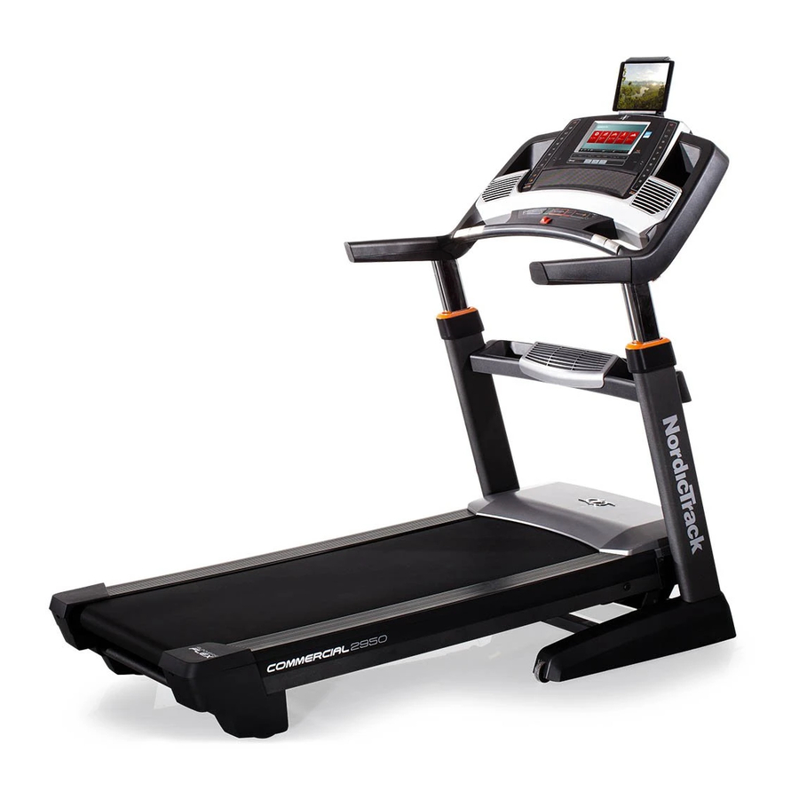
Model No. NETL29716.0
Serial No.
Write the serial number in the space
above for reference.
Serial Number
Decal
CUSTOMER SERVICE
UNITED KINGDOM
Call: 0330 123 1045
From Ireland: 053 92 36102
Website: www.iconsupport.eu
E-mail: csuk@iconeurope.com
Write:
ICON Health & Fitness, Ltd.
Unit 1D, The Gateway
Fryers Way, Silkwood Park
OSSETT
WF5 9TJ
UNITED KINGDOM
AUSTRALIA
Call: 1800 993 770
E-mail: australiacc@iconfitness.com
Write:
ICON Health & Fitness
PO Box 635
WINSTON HILLS NSW 2153
AUSTRALIA
CAUTION
Read all precautions and instruc-
tions in this manual before using
this equipment. Save this manual
for future reference.
USER'S MANUAL
www.iconeurope.com
Advertisement
Table of Contents

Related Manuals for NordicTrack NETL29716.0


Summary of Contents for NordicTrack NETL29716.0
- Page 1 Model No. NETL29716.0 Serial No. USER’S MANUAL Write the serial number in the space above for reference. Serial Number Decal CUSTOMER SERVICE UNITED KINGDOM Call: 0330 123 1045 From Ireland: 053 92 36102 Website: www.iconsupport.eu E-mail: csuk@iconeurope.com Write: ICON Health & Fitness, Ltd.
-
Page 2: Table Of Contents
Note: The decals may not be shown at actual size. 305284 The BLUETOOTH word mark and logos are registered trademarks of Bluetooth SIG, Inc. ® and are used under license. Google Maps is a trademark of Google Inc. NORDICTRACK is a registered trademark of ICON Health & Fitness, Inc. -
Page 3: Important Precautions
IMPORTANT PRECAUTIONS WARNING: To reduce the risk of burns, fire, electric shock, or injury to persons, read all important precautions and instructions in this manual and all warnings on your treadmill before using your treadmill. ICON assumes no responsibility for personal injury or property damage sus- tained by or through the use of this product. - Page 4 19. Keep fingers, hair, and clothing away from 24. When folding or moving the treadmill, make the moving walking belt. sure that the storage latch is holding the frame securely in the storage position. 20. The treadmill is capable of high speeds. Adjust the speed in small increments to 25.
-
Page 5: Before You Begin
BEFORE YOU BEGIN Thank you for selecting the revolutionary reading this manual, please see the front cover of this NORDICTRACK COMMERCIAL 2950 treadmill. The manual. To help us assist you, please note the product ® COMMERCIAL 2950 treadmill offers an impressive model number and serial number before contacting us. -
Page 6: Part Identification Chart
PART IDENTIFICATION CHART Use the drawings below to identify small parts used for assembly. The number in parentheses below each draw- ing is the key number of the part, from the PART LIST near the end of this manual. The number following the key number is the quantity used for assembly. -
Page 7: Assembly
ASSEMBLY • Assembly requires two persons. • To identify small parts, see page 6. • Place all parts in a cleared area and remove the • Assembly requires the following tools: packing materials. Do not dispose of the packing materials until you finish all assembly steps. the included hex key •... - Page 8 3. Insert the fan wire (A) into the left Upright (84). 88, 8 Next, slide the Left Base Cover (89) onto the left Upright (84), and slide the Right Base Cover (90) onto the right Upright. Tip: You may need to use a standard screwdriver to pull the Left Base Cover away from the left Upright so that the Left Base Cover will slide over the welded...
-
Page 9: Tighten Them
5. Attach the Tray (79) to the left and right Tray Brackets (76) with four #8 x 3/4" Truss Head Screw (24); start all four Truss Head Screws, and then tighten them. Make sure that no wires are pinched. Front View 6. -
Page 10: 3/4" Screws (6); Start All Four Screws, And Then
8. Set the console assembly (F) face down on a soft surface to avoid scratching the console assembly. Remove and discard the four indicated screws (G). Then, remove the Pulse Crossbar (80). 9. IMPORTANT: To avoid damaging the Pulse Crossbar (80), do not use power tools, and do not overtighten the #10 x 3/4"... -
Page 11: Tighten Them
10. With the help of a second person, hold the con- sole assembly (F) near the Handrails (74). Connect the ground wire (L) from the console assembly (F) to the Console Ground Wire (152) on the Pulse Crossbar (80). See the inset drawing. Connect the Upright Wire (83) to the console wire (H). -
Page 12: Tighten Them
12. Start four #8 x 3/4" Truss Head Screw (24) into the Pulse Crossbar (80), and then tighten them; do not overtighten the Truss Head Screws. 13. Set the Left Handrail Top Cover (73) on the left Handrail (74). Start four #8 x 3/4" Truss Head Screws (24) into the Left Handrail Bottom Cover (75), the left Handrail, and the Left Handrail Top Cover. - Page 13 14. Raise the Frame (52) to the position shown. Have a second person hold the Frame until step 15 is completed. Remove the 5/16" Nut (9) and the 5/16" x 1 3/4" Bolt (3) from the bracket on the Uprights (84). Next, orient the Storage Latch (56) as shown.
- Page 14 16. Press the two tabs on the Tablet Holder (16) into the slots (K) in the console assembly (F). Attach the Tablet Holder (16) with four #8 x 5/8" Machine Screws (108). Note: Start the two top Start First Machine Screws first, and then start the two bottom Machine Screws.
-
Page 15: The Chest Heart Rate Monitor
THE CHEST HEART RATE MONITOR HOW TO PUT ON THE HEART RATE MONITOR • Store the heart rate monitor in a warm, dry place. Do not store the heart rate monitor in a plastic bag or If the heart rate monitor looks like the one shown other container that may trap moisture. -
Page 16: How To Use The Treadmill
HOW TO USE THE TREADMILL HOW TO PLUG IN THE POWER CORD Follow the steps below to plug in the power cord. This product must be earthed. If it should malfunc- 1. Plug the indicated end of the power cord into the tion or break down, earthing provides a path of least socket on the treadmill. -
Page 17: How To Upgrade The Console
HOW TO UPGRADE THE CONSOLE The treadmill console has been preconfigured to operate with a digital TV (see the drawings below). To learn about the features of the console, see page 18. To learn about the features of the digital TV, see the user’s manual included with the digital TV. - Page 18 CONSOLE DIAGRAM MAKE YOUR FITNESS GOALS A REALITY WITH FEATURES OF THE CONSOLE IFIT.COM The advanced treadmill console offers an array of fea- With your new iFit-compatible fitness equipment, you tures designed to make your workouts more effective can use an array of features on iFit.com to make your and enjoyable.
- Page 19 HOW TO TURN ON THE POWER Note: The console can display speed and distance in either miles or kilometers. To find which unit of IMPORTANT: If the treadmill has been exposed to measurement is selected, see step 4 on page 26. cold temperatures, allow it to warm to room tem- For simplicity, all instructions in this section refer to perature before you turn on the power.
- Page 20 HOW TO SET UP THE CONSOLE To use the equipment settings mode, see page 26. To use the sound system, see page 27. To Before using the treadmill for the first time, set up the use the Internet browser, see page 28. To use the maintenance mode, see page 28.
- Page 21 The walking belt will begin to move at 2 Km/H. As As you walk or run on the treadmill, the screen can you exercise, change the speed of the walking belt show the following workout information: as desired by pressing the Speed increase and decrease buttons.
- Page 22 To measure your heart rate, stand on the foot HOW TO USE AN ONBOARD WORKOUT rails and hold the contacts with your palms for approximately ten seconds; avoid moving your 1. Insert the key into the console. hands. When your pulse is detected, your heart rate will be shown.
- Page 23 HOW TO USE A SET-A-GOAL WORKOUT The workout will continue in this way until the last segment ends. The walking belt will then slow to a stop and a workout summary will appear on the 1. Insert the key into the console. screen.
- Page 24 HOW TO USE AN IFIT WORKOUT The workout will continue until you reach the goal that you set. The walking belt will then slow to a stop, and a workout summary will appear on the Note: To use an iFit workout, you must have access screen.
- Page 25 6. Monitor your progress with the displays. To compete in a race that you have previously scheduled, touch the Compete button. To view your Workout History, touch the Track button. To use a See step 5 on page 21. The screen may also set-a-goal workout, touch the Set A Goal button show a map of the trail you are walking or running.
- Page 26 HOW TO USE THE EQUIPMENT SETTINGS MODE 6. Select an update time. 1. Select the settings main menu. To select a time for automatic firmware updates, touch the Update Time button and select the Insert the key into the console desired time.
- Page 27 9. Enable or disable the street view. 12. Set a safety screen timeout. During some workouts, the screen may show a The console features an automatic screen reset; if map. To enable or disable the street view feature of no buttons are touched or pressed and the walking the maps, first touch the Street View button.
- Page 28 HOW TO USE THE INTERNET BROWSER 3. Update the console firmware. Note: To use the browser, you must have access to a For the best results, regularly check for firm- ware updates. wireless network including an 802.11b/g/n router with SSID broadcast enabled (hidden networks are not supported).
- Page 29 IMPORTANT: Keep pets, feet, and other objects 3. Enable Wi-Fi. away from the treadmill while the incline sys- tem is calibrating. In an emergency, pull the key Make sure that the Wi-Fi checkbox is marked with from the console to stop the incline calibration. a green checkmark.
- Page 30 HOW TO ADJUST THE CUSHIONING SYSTEM To disconnect from a wireless network, select the wireless network and then touch the Forget button. The treadmill features a cushioning system that If you are having problems connecting to an reduces the impact as you walk or run on the treadmill. encrypted network, make sure that your password is correct.
-
Page 31: How To Fold And Move The Treadmill
HOW TO FOLD AND MOVE THE TREADMILL HOW TO FOLD THE TREADMILL HOW TO MOVE THE TREADMILL To avoid damaging the treadmill, adjust the incline Before moving the treadmill, fold it as described at the to zero before you fold the treadmill. Then, remove left. -
Page 32: Maintenance And Troubleshooting
MAINTENANCE AND TROUBLESHOOTING MAINTENANCE SYMPTOM: The power turns off during use Regular maintenance is important for optimal perfor- a. Check the power switch (see drawing c at the left). mance and to reduce wear. Inspect and properly tighten If the switch has tripped, wait for five minutes and all parts each time the treadmill is used. - Page 33 Locate the Reed Switch (146) and the Magnet b. If the walking belt is overtightened, treadmill per- (145) on the left side of the Pulley (51). Turn the formance may decrease and the walking belt may Pulley until the Magnet is aligned with the Reed become damaged.
- Page 34 SYMPTOM: The walking belt is not centered SYMPTOM: The tablet holder does not stay in place between the foot rails a. Rotate the tablet holder backwards. Then, tighten a. IMPORTANT: If the walking belt rubs against the the indicated screw slightly until the tablet holder foot rails, the walking belt may become dam- stays in place when it is rotated to the desired aged.
-
Page 35: Exercise Guidelines
EXERCISE GUIDELINES Burning Fat—To burn fat effectively, you must exer- WARNING: cise at a low intensity level for a sustained period of Before beginning this time. During the first few minutes of exercise, your or any exercise program, consult your physi- body uses carbohydrate calories for energy. - Page 36 SUGGESTED STRETCHES The correct form for several basic stretches is shown at the right. Move slowly as you stretch —never bounce. 1. Toe Touch Stretch Stand with your knees bent slightly and slowly bend forward from your hips. Allow your back and shoulders to relax as you reach down toward your toes as far as possible.
- Page 37 NOTES...
-
Page 38: Part List
PART LIST Model No. NETL29716.0 R0616A Key No. Qty. Description Key No. Qty. Description 5/16" x 3/4" Screw Drive Roller/Pulley 5/16" x 2" Screw Frame 5/16" x 1 3/4" Bolt 5/16" x 2 1/4" Bolt Drive Motor #8 x 3/4" Screw Motor Belt #10 x 3/4"... - Page 39 Key No. Qty. Description Key No. Qty. Description Right Tray Standoff 1/2" Thrust Washer Power Supply Plate Controller Clamp Upright Motor Spacer Key/Clip 1/4" x 3/4" Screw Console Frame Cap 1/4" x 1 1/2" Screw Console Frame 1/4" x 1 5/8" Screw Wire Tie 1/4"...
-
Page 40: Exploded Drawing
EXPLODED DRAWING A Model No. NETL29716.0 R0616A... - Page 41 EXPLODED DRAWING B Model No. NETL29716.0 R0616A 149 112 115 30...
- Page 42 EXPLODED DRAWING C Model No. NETL29716.0 R0616A...
- Page 43 EXPLODED DRAWING D Model No. NETL29716.0 R0616A...
-
Page 44: Ordering Replacement Parts
ORDERING REPLACEMENT PARTS To order replacement parts, please see the front cover of this manual. To help us assist you, be prepared to provide the following information when contacting us: • the model number and serial number of the product (see the front cover of this manual) •...
Need help?
Do you have a question about the NETL29716.0 and is the answer not in the manual?
Questions and answers