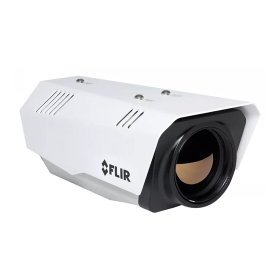
FLIR FC-Series Quick Connect Manual
Id camera
Hide thumbs
Also See for FC-Series:
- Quick connect manual (4 pages) ,
- Quick connect manual (2 pages) ,
- Installation manual (72 pages)
Advertisement
Quick Links
3 mm hex
Caution!
Except as described in this guide, do not disassemble the FC-Series ID camera.
Damage to the camera can occur as the result of careless handling or
electrostatic discharge (ESD).
Before installing the FC-Series ID camera you should read and understand the
following documents which provide details regarding mechanical dimensions
and installation safety.
•
FLIR FC-Series ID Installation Manual (427-0089-00-12)
•
FLIR FC-Series ID Interconnect Document (427-00XX-YY-41)
Power: Power Over Ethernet Plus (PoE+) or 11 - 32 Vdc or 18 - 32 Vac
Power terminal blocks: wire size from 16 AWG to 20 AWG
Analog Video Cable: BNC-terminated RG-59/U solid-center coax cable
Ethernet Cable: Cat5e or Cat6
Accessory I/O plugs: conductor size 22 - 24 AWG, stranded, 1.6 mm max
diameter including insulation for IDC fast connect. Otherwise, 20 - 24 AWG for
push-in spring connect, strip ends 6 mm. GPIO accessory cable.
FLIR Systems, Inc.
6769 Hollister Avenue
Goleta, CA 93117
USA
Support:
http://www.flir.com/security/display/?id=71083
427-0089-00-28 Rev 120
key
Items Included in Kit
FC-Series ID Camera
Quick Connect Guide
Corporate Headquarters
27700 SW Parkway Ave.
Wilsonville, OR 97070
USA
Slotted
screwdriver
July 2016
Advertisement

Summary of Contents for FLIR FC-Series
- Page 1 3 mm hex Items Included in Kit Caution! Except as described in this guide, do not disassemble the FC-Series ID camera. Damage to the camera can occur as the result of careless handling or electrostatic discharge (ESD). Before installing the FC-Series ID camera you should read and understand the following documents which provide details regarding mechanical dimensions and installation safety.
- Page 2 Step 1 Remove cover: Using 3 mm hex key, loosen four captive screws. Access screws through slots in sunshield. Removing the sunshield is not necessary. Step 2 Install cables through sealing gland: Fill any unused hole with orange plug. Re-tighten Gland nut gland nut after installation is completed.
- Page 3 Step 7 Discover camera: Power the camera. With a PC connected to the camera network, use the DNA utility to discover and display the camera’s current IP address. a. Download the DNA utility (2.1.2.7 or later) from the FLIR Firmware & Software Downloads page at: http://www.flir.com/security/display/?id=73533.
- Page 4 d. To create an Area, Tripwire, or Masking Area, click the icon and select from the Type drop-down list. e. Define the Area, Tripwire, or Masking Area by clicking vertex locations on the screen. Click Finish. g. In the Regions pane select the tripwire.


Need help?
Do you have a question about the FC-Series and is the answer not in the manual?
Questions and answers