Table of Contents
Advertisement
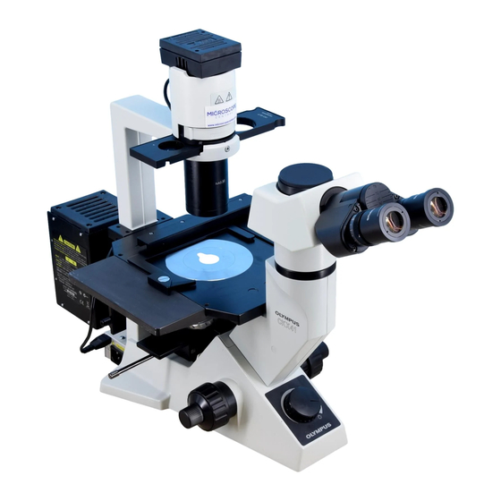
This instruction manual is for the Olympus Culture Microscopes Models CKX41 and CKX31. To
ensure the safety, obtain optimum performance and to familiarize yourself fully with the use of this
microscope, we recommend that you study this manual thoroughly before operating the microscope.
Retain this instruction manual in an easily accessible place near the work desk for future reference.
CKX41 /CKX31
CULTURE MICROSCOPES
INSTRUCTIONS
Ryf AG
Bettlachstrasse 2
2540 Grenchen
tel 032 654 21 00
fax 032 654 21 09
www.ryfag.ch
A X 7 3 5 1
Advertisement
Table of Contents

Related Manuals for Olimpus CKX41

Summary of Contents for Olimpus CKX41
- Page 1 CKX41 /CKX31 CULTURE MICROSCOPES This instruction manual is for the Olympus Culture Microscopes Models CKX41 and CKX31. To ensure the safety, obtain optimum performance and to familiarize yourself fully with the use of this microscope, we recommend that you study this manual thoroughly before operating the microscope.
-
Page 3: Table Of Contents
CKX41/CKX31 CONTENTS IMPORTANT — Be sure to read this section for safe use of the equipment. — NOMENCLATURE CONTROLS SUMMARY OF OBSERVATION PROCEDURE USING THE CONTROLS 9-15 4-1 Microscope Frame ....................................9 Turning On the Light Source Adjusting the Brightness Adjusting the Tension of the Coarse Adjustment Knob 4-2 Stage............................................. -
Page 5: Safety Precautions
CKX41/CKX31 IMPORTANT The difference between the CKX31 and CKX41 microscopes lie in the following basis systems. CKX31 CKX41 Replaceable * Observation tube Binocular tube fixed Replaceable ** Stage center plate – Reflected fluorescence system Not mountable Mountable * The U-CBI30-2/U-BI30-2/U-CTBI/CKX-TBI binocular tube or U-CTR30-2/U-TR30-2 trinocular tube can be mounted. - Page 6 9. The microscope system is unstable when the large camera back is attached. When pulling out the film, be sure to hold the micro- scope with one hand. 10. Always turn the light intensity control knob 5 gently. Do not at- tempt to turn it beyond the stop position.
-
Page 7: Maintenance And Storage
CKX41/CKX31 Maintenance and Storage 1. To clean the lenses and other glass components, simply blow dirty away using a commercially available blower and wipe gently using a piece of cleaning paper (or clean gauze). If a lens is stained with fingerprints or oil smudges, wipe it gauze slightly moistened with commercially available absolute alcohol. -
Page 8: Nomenclature
NOMENCLATURE CKX31 Lamp Socket Phase Contrast Slider U-LS30-3 · Pre-centered Ph slider: IX2-SLP · Ph centering slider: IX2-SL Objectives For brightfield observation: PlanCN 4X PlanCN 10X PlanCN 20X PlanCN 40X PlanCN 60X PlanCN 100XO Illumination #Dedicated objectives are required Column (Fixed) for phase contrast observations (see page 17). - Page 9 CKX41/CKX31 CKX41 Lamp Socket Phase Contrast Slider U-LS30-3 · Pre-centered Ph slider: IX2-SLP · Ph centering slider: IX2-SL Objectives Illumination Column (Fixed) For brightfield observation: PlanCN 4X PlanCN 10X PlanCN 20X PlanCN 40X PlanCN 60X PlanCN 100XO #Dedicated objectives are required for phase contrast observations (see page 17).
-
Page 10: Controls
CONTROLS CKX31 }If you have not yet assembled the microscope, read chapter 9, “ASSEMBLY” (pages 25 to 29). Filter holder (Page 29) Phase contrast slider (Page 16) Aperture iris diaphragm lever (Page 15) Interpupillary distance scale (Page 11) Slider centering knob storage holes Diopter adjustment ring (Page 12) -
Page 11: Controls
CKX41/CKX31 CKX41 }If you have not yet assembled the microscope, read chapter 9, “ASSEMBLY” (pages 25 to 29). Filter holder (Page 29) Phase contrast slider Interpupillary distance (Page 16) scale (Page 11) Aperture iris diaphragm lever (Page 15) Diopter adjustment ring... -
Page 12: Summary Of Observation Procedure
SUMMARY OF OBSERVATION PROCEDURE 1. Set the main switch 1 to “ I ” (ON) and turn the light intensity control knob 2 to obtain appropriate brightness. (Page 9) ² 2. When using the U-TR30-2 trinocular tube, push in the light path selector knob 3 to set the light path at 100% for binocular observation. -
Page 13: Using The Controls
CKX41/CKX31 USING THE CONTROLS 4-1 Microscope Frame Turning On the Light Source (Fig. 3) Set the main switch 1 on the side panel of the microscope frame to “ I ” (ON). Fig. 3 Adjusting the Brightness (Fig. 4) Turn the light intensity control 1 clockwise to raise the voltage and increase the brightness. -
Page 14: Stage
When Using a 35 mm Petri Dish }With the CKX41, a 35 mm petri dish can be mounted directly on the stage provided that the standard stage center plate is in use. 1. With the CKX31, put the provided 35 mm petri dish holder 1 on the stage and mount the 35 mm petri dish on the opening in the center. -
Page 15: Observation Tube
(Fig. 9) }Note your interpupillary distance so that it can be quickly duplicated. Fig. 9 With the CKX41 }When the observation tube is the U-CBI30-2, U-CTR30-2 or U-CTBI, fol- low the procedure in "With the CKX31". -
Page 16: Adjusting The Diopter
2. While looking through the right eyepiece with your right eye, turn only the diopter adjustment ring 1 to focus on the specimen. (Fig. 11) Fig. 11 With the CKX41 ² }When the U-CTBI is used, align the white dot · with the index line on the scale of the right eyepiece’s diopter adjustment ring. - Page 17 CKX41/CKX31 Using the Eyepiece Micrometer Disk (Figs. 15) }When the WHN10X-H (or WHN10X) eyepieces are used, an eyepiece micrometer disk can be inserted in one of them. When the eyepiece does not have a diopter adjustment mechanism, however, it is hard to focus on the micrometer disk if the operator has poor eyesight.
-
Page 18: Selecting The Light Path (U-Tr30-2 Only)
Selecting the Light Path (U-TR30-2 Only) (Fig. 16) Slide the light path selector knob 1 to select the desired light path. Light Path Symbol Intensity Ratio Applications Selector Knob Pushed in 100% for binocular Observation of dark eyepieces specimens Middle position 20% for binocular Observation of eyepieces, 80% for... -
Page 19: Illumination Column
CKX41/CKX31 4-4 Illumination Column Using the Filters }Using appropriate filters according to the purposes allows you to observe and photograph specimens more effectively. Particularly, the use of the LBD filter is recommended in observation and photomicrography because it renders more neutral colors. -
Page 20: Objective Correction Collars
4-5 Objective Correction Collars Correction Collar (Fig. 20) }A culture microscope is designed to observe specimens contained in vessels of various bottom thickness values. In order to achieve optimum objective performance of the culture microscope, the LUCPlanFLN20X, 40X, 60X, etc. are provided with a correction collar @. The correction is possible according to the vessel thickness. -
Page 21: Phase Contrast Observation
CKX41/CKX31 PHASE CONTRAST OBSERVATION The following two slider units are available for phase contrast observation. Mount a slider onto the microscope and replace the objectives with phase contrast compatible objectives. Model Name Description Applicable Objectives (Note) Ph precentering slider · The light annuli are precentered, so no adjustment... -
Page 22: Phase Contrast Observation
Mounting the Optical Element (Fig. 21) ³ }When the IX2-SL phase contrast slider is used, it is required to attach an optical element matching the phase objective in use. 1. Hold the IX2-SLPH2 optical element 1 so that engraving faces upward and drop in the optical element in the empty position 2. - Page 23 CKX41/CKX31 Centering the Light Annulus (Figs. 23 & 24) ² # The IX2-SLP does not need to be centered. However, as the phase contrast effect near the vessel edge tends to drop because the light annulus image may be deformed due to the liquid surface curvature (surface tension).
-
Page 24: Photomicrography & Tv Observation
PHOTOMICROGRAPHY & TV OBSERVATION C-mount TV camera TV camera Photomicrographic system PM10 PM20 TV camera mount adapter PM30, etc. U-BMAD (Note) The system U-IMAD becomes U-CMAD3, etc. unstable when a large TV adapter camera back U-PMTVC TV adapter is used. U-TV0.5X U-TV1X-2 (The U-TV1X cannot be attached to the U-CTR30-2.) -
Page 25: Troubleshooting Guide
CKX41/CKX31 TROUBLESHOOTING GUIDE Under certain conditions, performance of the unit may be adversely affected by factors other than defects. If problems occur, please review the following list and take remedial action as needed. If you cannot solve the problem after checking the entire list, please contact Olympus for assistance. - Page 26 Trouble Cause Remedy Page f ) One side of image is blurred. The revolving nosepiece is not correctly Make sure that the revolving nosepiece engaged. clicks properly into place. The specimen is not correctly mounted Place it correctly on the stage. on the stage.
-
Page 27: Specifications
CKX41/CKX31 SPECIFICATIONS Specification Item CKX31 CKX41 1. Optical system UIS2/UIS (Universal Infinity System) optical system 2. Illumination Built-in transmitted Koehler illumination High-intensity halogen bulb 6V30WHAL (PHILIPS 5761) (Average life time: Approx. 100 hr. when used as directed) Output rating: 6 V... - Page 28 Specification Item CKX31 CKX41 7. UIS2 Objectives Brightfield PlanCN4X N.A. 0.10, W.D. 18.5 mm, resolution 3.36 μm (UIS series PlanCN10X N.A. 0.25, W.D. 10.5 mm, resolution 1.30 μm PlanCN20X N.A. 0.40, W.D. 1.2 mm, resolution 0.84 μm objectives can PlanCN40X N.A.
-
Page 29: Assembly
CKX41/CKX31 ASSEMBLY 9-1 Assembly Diagram The diagram below shows the sequence of assembly of the various modules. The numbers indicate the order of assembly. # When assembling the microscope, make sure that all parts are free of dust and dirt, and avoid scratching any parts or touching glass surfaces. - Page 30 9-2 Detailed Assembly Procedures Installing/Replacing the Halogen Bulb (Fig. 25) }Use only the designated high-intensity halogen bulb 6V30WHAL (PHILIPS ² 5761). To prevent reduced bulb life or cracking, do not touch the bulb with bare hands. If fingerprints are accidentally left on the bulb, wipe the bulb with a soft cloth.
- Page 31 Fig. 28 low to high. }Mounting the objectives this way makes it easier to change magnification. }With the CKX41, the objectives can be mounted through the opening on the stage. ² # Clean the objectives periodically. The objective tips on a culture mi- croscope are susceptible to dust.
- Page 32 Mounting the Stage Center Plate (CKX41 Only) (Fig. 31) ² Fit the standard stage center plate 1 into the opening on the stage. }Turn the center plate so that the notch 2 faces to the front for easy confirmation of the objective tip.
- Page 33 CKX41/CKX31 Mounting the Filters (Figs. 34 & 35) ² Let the filters cool down sufficiently before replacing them. Take out the filter holder 1 and insert the required filters 2. # Push the filter down to the bottom as shown in Fig. 35 so that it does not tilt.
-
Page 34: Proper Selection Of The Power Supply Cord
PROPER SELECTION OF THE POWER SUPPLY CORD If no power supply cord is provided, please select the proper power supply cord for the equipment by referring to “ Specifications ” and “ Certified Cord ” below: CAUTION: In case you use a non-approved power supply cord for Olympus products, Olympus can no longer warrant the electrical safety of the equipment. - Page 35 CKX41/CKX31 Table 2 HAR Flexible Cord APPROVAL ORGANIZATIONS AND CORDAGE HARMONIZATION MARKING METHODS Alternative Marking Utilizing Printed or Embossed Harmoniza- Black-Red-Yellow Thread (Length tion Marking (May be located on Approval Organization of color section in mm) jacket or insulation of internal wir-...
-
Page 36: Lamp Socket Inspection Sheet
LAMP SOCKET INSPECTION SHEET {Study the instruction manual for the lamp socket before inspection. {For safe use of the lamp socket, we recommend performing the following inspection periodically (every time you replace the lamp bulb and at least every 6 months). {The table below identified the check items to be observed. - Page 37 MEMO...
- Page 38 MEMO...
- Page 40 Shinjuku Monolith, 3-1, Nishi Shinjuku 2-chome, Shinjuku-ku, Tokyo, Japan Postfach 10 49 08, 20034, Hamburg, Germany 3500 Corporate Parkway, P.O. Box 610, Center Valley, PA 18034-0610, U.S.A. 491B River Valley Road, #12-01/04 Valley Point Office Tower, Singapore 248373 31 Gilby Road, Mount Waverley, VIC., 3149, Australia 5301 Blue Lagoon Drive, Suite 290 Miami, FL 33126, U.S.A.
Need help?
Do you have a question about the CKX41 and is the answer not in the manual?
Questions and answers