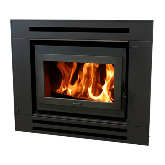
Masport I9000 Installation Instructions Manual
Inbuilt
Hide thumbs
Also See for I9000:
- Installation instructions manual (6 pages) ,
- Installation instructions manual (15 pages) ,
- Installation insrtuctions (7 pages)
Advertisement
Quick Links
MASPORT I9000 INBUILT FIRE
INSTALLATION INSTRUCTIONS
Manufactured in New Zealand by:
GLEN DIMPLEX AUSTRALASIA LIMITED
38 Harris Road, East Tamaki
Auckland
Ph: 0800 666 2824
Fax: 09274 8472
Email: sales@glendimplex.co.nz
Web: www.glendimplex.co.nz
12.01.2011
Part. No. 593359
Distributed in Australia by:
GLEN DIMPLEX AUSTRALIA PTY LIMITED
Unit 2, 205 Abbotts Road, Dandenong South
Victoria, 3175
Ph: 1 300 566 816
Fax: 1 800 058 900
Email: sales@glendimplex.com.au
Web: www.glendimplex.com.au
1
Advertisement

Subscribe to Our Youtube Channel
Summary of Contents for Masport I9000
- Page 1 MASPORT I9000 INBUILT FIRE INSTALLATION INSTRUCTIONS Manufactured in New Zealand by: Distributed in Australia by: GLEN DIMPLEX AUSTRALASIA LIMITED GLEN DIMPLEX AUSTRALIA PTY LIMITED 38 Harris Road, East Tamaki Unit 2, 205 Abbotts Road, Dandenong South Auckland Victoria, 3175 Ph: 0800 666 2824...
- Page 2 CONTENTS ZERO CLEARANCE BOX (SHIELDING BOX) KIT PART NO. DESCRIPTION 523031 WASHER DIA 6 521635 SCREW HEX. 10G X 10mm 521637 SCREW HEX. 12G X 25mm 521643 SCREW HEX. 8G X 13mm 521076 SCREW HEX. M6 X 16mm 593374 ADAPTOR SPIGOT RING 993390 L/H SIDE PANEL ASSEMBLY 993391...
- Page 3 The model I9000 has been tested to demonstrate compliance with current general emission re- quirements in Australia and New Zealand, but some areas have stricter limits. So check before...
- Page 4 CAUTION: CRACKED OR BROKEN COMPONENTS, E.G. GLASS PANELS, MAY RENDER THE INSTALLATION UNSAFE. NOTE The following instructions cover the installation of the model I9000 Inbuilt Fire complete with a ‘zero clearance’ metal shielding box, ‘zero clearance’ fascia and special ‘zero clearance’ flue kit.
- Page 5 Wall surfaces directly above the heater may reach 85 degrees C, so materials such as wallpaper and water based paint may be adversely affected. For durability of finishes and surfaces you should contact the relevant manufacturers for their specifications. Masport Heating accepts no responsibility for the deterioration of surfaces of finishes.
- Page 6 It is usually convenient to carry the same material right up to the ceiling level. At the lower edge, drill (4.5mm diameter) holes into the metal support angle through the holes in the top flange of the shielding box and fasten with the self threading screws provided. The side clad- ding of the enclosure may be Gib board or any other wall cladding material.
- Page 7 ward and outwards. Use two screws provided for each bracket. Slide the firebox cabinet into the shielding box. Centralize it and secure the restraint brackets to the shielding box flanges. Complete the seismic restraint of the fire by screwing the base plate of the fire to the bottom of the shielding box with two M6 screws.
- Page 8 Fig. 4 INSTALLATION ON COMBUSTIBLE FLOOR Fig. 5 INSTALLATION ON CONCRETE FLOOR...
- Page 9 Fig. 6 INSTALLATION- ELEVATED Fig. 7 INSTALLATION– BOX ENCLOSURE ON COMBUSTIBLE FLOOR...
- Page 10 HEIGHTS OF FLUE PIPE & CASINGS FOR Fig. 8 SFP COMBINATION COWEL ( Fixed Bracket) Fig. 9 HEIGHTS OF FLUE PIPE & CASINGS FOR SFP STANDARD CASING COVER & SFP TOP FLUE PIPE SPACER BRACKET NOTE: It is very important that the space between the flue pipe and the inner casing and the space between the inner casing and the outer casing are ventilated at the top.
-
Page 11: External Installations
NOTES FOR VARIATIONS CONCRETE FLOORS The above instructions assume that the heater is being installed on a heat sensitive floor such as timber or particle board. Where the floor is not heat sensitive (e.g. concrete), the insulating floor pro- tector may be omitted. However, if heat sensitive floor coverings (e.g.carpet) are fitted it will be nec- essary to keep them at a safe distance. -
Page 12: Installing The Fascia
INSTALLING THE FASCIA Unpack fascia and lay flat on floor front face up, carful not to scratch the paintwork. Remove the vent cover panel (item 1) which will be just above the door on the final installation. It is secured with two screws. - Page 13 Position the power cord with the three pin plug at the end through the slot at the bottom end of the left hand fascia panel. Make sure the small rubber grommet is inserted into the slot to protect the mains lead against possible damage.. Move fascia to the front of fire, slide it in and lift it up about 15mm above its final position.


Need help?
Do you have a question about the I9000 and is the answer not in the manual?
Questions and answers