
Related Manuals for Meteor Manuale Compact 400 Plus

Summary of Contents for Meteor Manuale Compact 400 Plus
- Page 1 MANUALE COMPACT 400 PLUS (R-400 PLUS) MANUALE COMPACT 600 (R-600) STAMPANTI DI CODICI A BARRE COMMERCIALI www.meteorbarcode.it - info@meteorbarcode.it...
-
Page 2: Table Of Contents
13. Caring for Your Printer……………….………. 54 CONTENTS 13.1 Cleaning the print head (THP) 13.2 Cleaning the roller Page 13.3 Cleaning the media compartment Checking Your Box…………………………….. 1 14. Reference Technical Information……………... 55 Power Supply…………………………………… 2 14.1 General Specifications Parts and Features……………………………... 3 14.2 Fonts, Bar Codes and Graphics Specification Loading the Ribbon……………………………. -
Page 3: Checking Your Box
1. Checking Your Box 2. Power Supply Receiving the box of your printer, you are advised to check first for WARNING: the possible shipping damage. There are two ways you can do it: NEVER OPERATE THE PRINTER AND POWER SUPPLY IN AN AREA WHERE THEY CAN GET WET. -
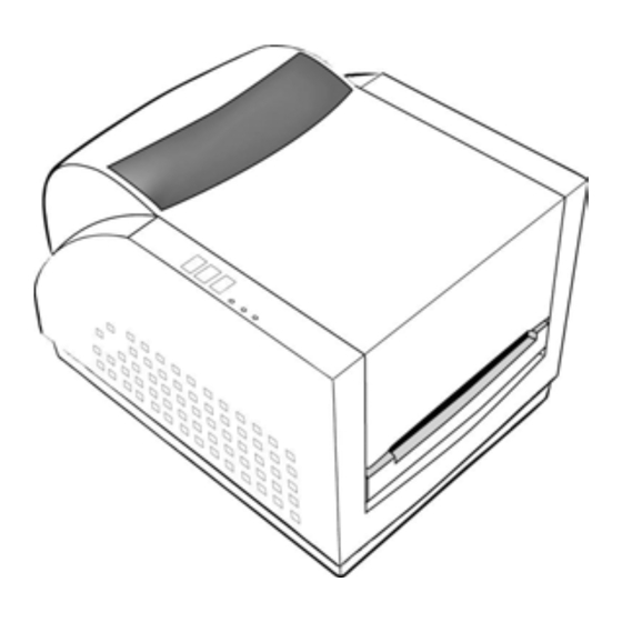
Page 4: Parts And Features
3. Parts and Features Media Hanger Top Cover Release Levers Ribbon Pick-up Holder Thermal Printhead Power Switch Cover Lock Ribbon Supply Holder Cover Lock Power Switch Platen Roller www.meteorbarcode.it - info@meteorbarcode.it... -
Page 5: Loading The Ribbon
4. Loading the Ribbon Unlatch the print head module by pushing the two green release levers on the sides toward the rear. This allows print head module to rotate upward Note: automatically and expose the ribbon supply holder. This section is not applicable to the direct thermal printing. Press the cover locks on both sides to open the top cover Print Head Module Release Lever... - Page 6 Unwrap the ribbon roll pack and separate the ribbon roll Turn back the print head module and then insert the bare and the bare core. core into the pick-up holder. (First snap in the right side, Attach the edge of the ribbon on the bare core and wind it then the left side.) a little bit onto the core.
-
Page 7: Loading The Media
Turn the wheel of the print head module to ensure the 5. Loading the Media ribbon is tightly wound. Press down the print head module firmly on both sides till R-Series printers can be operated in three different options: you hear a snap. standard, peel-off, or with a cutter. -
Page 8: Standard Mode
5.1 Standard Mode 5.1.4 Unlatch the print head module. 5.1.5 Hold the print head module upright with one hand to 5.1.1 Press the cover locks on both sides to swing the top allow the media pass under it. Lead the media cover toward the rear and expose the media through the media guides with the other hand. - Page 9 5.1.8 Turn back the print head module and then press it 5.1.9 Close the top cover and turn on the printer or press down firmly on both sides till you hear a snap. feed button if the printer is already on. Feed Button Print Head Module Note:...
-
Page 10: Peel Off Mode
5.2 Peel Off Mode 5.2.2 Trim the edge of label backing paper with scissors or knife. 5.2.3 Push down peeler-switch to ease the access packing (Installing the dispenser kit, please refer to the Appendix C.) paper. Follow the common procedure of "Loading the Media "of 5.2.4 Lead the backing paper over the plate, then thread it back Standard Mode from step 5.1.1 to step 5.1.9. -
Page 11: Cutter Mode
5.2.6 Latch print head module 5.3 Cutter Mode 5.2.7 Turn on the printer and press feed button. (Installing the cutter, please refer to Appendix D ) 5.2.8 Labels will be separated from backing paper and fed out Follow the same procedure as "Loading the Media" from on H cover, while backing paper will come out from the step 5.1.1 to step 5.1.9. -
Page 12: Operator Controls
5.3.3 Press down the print head module firmly. 6. Operator Controls 6.1 Power Switch Controls printer power On-normal operation Off-the power should be turned off before connect or disconnect the communication cables and power cables Cutter 6.2 Buttons There are three buttons, each has two basic functions BUTTON Pressed at normal status Pressed during power-on... -
Page 13: Led Indicators
6.3 LED Indicators 3. Before calibration, the media and ribbon must be loaded properly and move the label sensor to correct position. There are three LED indicators on the front panel, “READY”, 4. After self-test, the printer is at dump mode, If you need “MEDIA”... -
Page 14: Performing Calibration
7. Performing Calibration 8. Printing Configuration Report After the media loaded, it is necessary to do the calibration for 8.1 Performing the Self Test the label size detection. 8.1.1 Turn off the printer. Press and hold the feed button. 8.1.2 Turn on the power. 7.1 Press and hold the pause button. -
Page 15: Default Settings
9. Resetting the Printer to Factory Note: 1. After self-test the printer will enter character dump mode. For Default Settings normal operation press the cancel button to exit from dump mode. If you would like to reset the printer to its factory defaults after 2. -
Page 16: Communicate With The Printer
10. Hooking up the Printer & Computer 11. Communicate with the Printer 10.1 Connecting the Printer to Your Host The bundled printer driver can be applied to all the applications under Windows XP/2000/98/95, and Windows NT. Through this 10.1 You can connect the printer with any standard Centronics driver you may run any popular software applications such as cable to the parallel port of the host computer. - Page 17 3. Select a driver for your 5. After the related files printer and click "Next". are copied to your For 203 dpi modes with 4 system, click “Next”. inches print width, you should select Label Dr.200 (4 inch model). 4. Select the port of the 6.
-
Page 18: Installing The Usb Driver (Plug And Play)
11.3 Installing the USB Driver (Plug and Play) Note: 1. If you are updating the driver, previous driver files are overwritten automatically. Note: 2. If you install new bar code application software such as The printer driver needs to install version 1.4.00 or later and ArgoBar, LabelView or CodeSoft, you may activate the support “USB Plug and Play”... - Page 19 5. Select “Search for the best driver in these locations” and choose 6. Select “Continue Anyway”. “Include this location in the search”. Input the location of printer driver, click “Next”. www.meteorbarcode.it - info@meteorbarcode.it...
- Page 20 7. Click “Finish”. 10. The system assigns the USB port for Label Dr200 (4 inch model) printer The Label Dr200 (4 inch model) printer is added in “Printers and Faxes”. 9. Reboot the system. www.meteorbarcode.it - info@meteorbarcode.it...
-
Page 21: For Win
11.4 Setting Parameters 11.4.1Parameters for Win 98 Ports After installing the driver, follow the path below to set parameters: In the Properties menu: Start → Settings→ Printers→ Label Dr.→ Properties → Click "Details" → Select the IO port. Parameters include: →... - Page 22 Create a custom size Output bin In the Properties menu: (Accessory setting) → Click "Paper" → Select "Custom" In the Properties menu: → User-Defined Size → Click "Paper" → Set a custom size → Click "More Options" → Click "OK" →...
- Page 23 11.4.2 Parameters for Win 2000 Orientation Page order In Printing Preferences: Ports → Click "Layout" → Select "Portrait" or In the Properties menu: "Landscape" → Click "Ports" → Click "Page order”" → Select the IO port → Select "Front to Back" →...
- Page 24 Paper size setup Create a custom size In Printing Preferences: In the Printers menu: → Click tag "Layout" → Right click → Click button "Advanced" → Select "Server → Click "button Customize”" Properties" → Select "paper size" or → Enter a form name for add new paper size.
- Page 25 11.4.3 For NT 4.0 Paper/Output (Speed) Print quality Ports (Darkness) In the Properties menu: In Default Document: → Click "Ports" → Click "Advanced" → Select IO port → Click item to select → Click "OK" desired parameters → Click "OK" Paper size Create a custom size Orientation...
-
Page 26: For Win Xp
11.4.4 For Win XP Orientation Page order Ports In Printing Preferences: → Click "Layout" In the Properties menu: → Select "Portrait" or → Click "Ports" "Landscape" → Select the IO port → Click "Page order”" → Click "OK" → Select "Front to Back" or "Back to Front"... - Page 27 Paper size setup Create a custom size In Printing Preferences: In the Printers menu: → Click tag "Layout" → Right click → Click button "Advanced" → Select "Server → Click button "Customize”" Properties" → Select "paper size" or → Enter a “Form name” Add new paper size.
-
Page 28: Troubleshooting
12. Troubleshooting 12.2 Problems on ribbon Generally, when a malfunction or an abnormal condition occurs, Possible Problems Solutions Remarks the “READY” LED will keep blinking and printing and Ribbon has run out Supply the ribbon roll. Does not apply to direct communication between the host and printer will stop. -
Page 29: Recovery
13. Caring for your Printer 12.3.3 Vertical streaks in the printout usually indicate a dirty or faulty print head. Clean the print head first, if they still persist, replace the print head. Before maintenance be sure to turn off the printer power. 13.1 Cleaning the print head (TPH) Turn off the printer, open the cover, print head module and remove the ribbon. -
Page 30: Reference Technical Information
14. Reference Technical Information Media Roll-feed, die-cut, continuous, fan-fold, tags, ticket in thermal paper or plain paper and fabric label Max width 4.3” (110 mm) 14.1 General Specifications Min width 1” (15 mm) Specifications R-400Zip R-400plus R-400 R-600 Thickness .0025”~. 01” (.0635mm ~. 254mm) Printing method Direct thermal &... -
Page 31: Fonts, Bar Codes And Graphics Specification
14.2 Fonts, Bar Codes and Graphics 14.2.2 Printer Programming Language B, PPLB Specification Specification R-400/ R-400plus / R-600 General fonts 5 fonts with different point sizes The specifications of fonts, bar codes and graphics depend on Symbol sets 8 bits: code page 437, 850, 852, 860, 863 and the printer emulation. -
Page 32: Interface Specifications
14.3 Interface Specifications Soft fonts Downloadable soft fonts Font expandability 2 to 10 times 14.3.1 Introduction Bar code types Code 39 (checksum), Code 93, Code 128/subset A,B,C, Codabar, Interleave 2 of 5 This appendix presents the interface specifications of I/O ports for the (checksum), Industrial 2 of 5, Standard 2 of 5, printer. -
Page 33: Usb
14.3.3 USB Alternatively you can just connect the 3 wires in the following way. Host 25S Printer 9P Host 9S Printer 9P (PC or compatible) (PC or compatible) TX 2 …… 2 RX TX 3 …… 2 RX RX 3 ……... -
Page 34: Parallel (Centronics)
14.4 ASCII TABLE If you run an application with the bundled printer driver under Windows and use the serial port, you should check the above parameters and set the flow control to “Xon/Xoff” or “hardware”. 0 NUL 1 SOH 14.3.5 Parallel (Centronics) 2 STX “... -
Page 35: Appendix
15. Appendix 15.2 Appendix B: Stand-Alone Operation Stand-Alone operation for keyboard and barcode reader 15.1 Appendix A: Printer Status Apart from related hardware devices and PPLB emulation, in order to use keyboards and barcode readers (scanner) you Blinking Description should follow apply with ArgoKee. 15.3 Appendix C: MEDIA The printer is at pause state. - Page 36 Remove gear (27) and (31). 11. Put back gear (27) and gear (31). Plug spring–peeler (83) into the right hole on chassis 2 and Mount the cable into chassis 2 and plug the other side lock screw (F) up. into the label on the main board. Put shaft-peeler (86) and peeler-switch (88) into 13.
-
Page 37: Appendix D : Cutter Installation
15.4 Appendix D : Cutter Installation Remove the E- ring(I), gear(27) and release the screw(F). Remove the bracket-peeler(71) from the module. 1. Turn off the power switch. 2. Remove the top cover and middle cover Top Cover H Cover Secure two attached screws (B) for the cable connector. Add a baby board to JP29 on the main board. - Page 38 Environmentally sensible disposal of electrical and electronic equipment Electrical and electronic equipment contains valuable materials that should be supplied to recycling or recovery. Please dispose of electrical and electronic equipment at qualified collecting points separate from municipal waste. www.meteorbarcode.it - info@meteorbarcode.it...
- Page 39 www.meteorbarcode.it - info@meteorbarcode.it...
Need help?
Do you have a question about the Manuale Compact 400 Plus and is the answer not in the manual?
Questions and answers