
Subscribe to Our Youtube Channel
Related Manuals for Toro 30659 LT-F3000


Summary of Contents for Toro 30659 LT-F3000
-
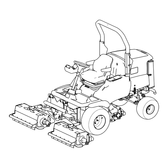
Page 1: Flail Mower
Form No. 3401-570 Rev A LT-F3000 Heavy-Duty Triple Turf Flail Mower Model No. 30659—Serial No. 316000001 and Up *3401-570* A Register at www.Toro.com. Original Instructions (EN) - Page 2 You may contact Toro for product safety and operation training materials, accessory information, help finding a dealer, or to register your product directly at www.Toro.com or Toro Commercial Products Service Department, Spellbrook, Bishops Stortford, CM23 4BU, England, +44(0)1279 603019, Email: uk.service@toro.com.
-
Page 3: Table Of Contents
Checking the Battery Condition........42 Safety ................4 Servicing the Battery..........43 Safe Operating Practices........... 4 Drive System Maintenance .........43 Toro Riding Mower Safety ........6 Changing the Transmission Oil Filter ......43 Sound Power Level ..........7 Changing the Hydraulic-Return Filter......44 Sound Pressure Level..........7 Checking the Rear-Wheel Alignment ......44... -
Page 4: Safety
Safety • Thoroughly inspect the area where the equipment is to be used and remove all objects which may be thrown by the machine. This machine has been designed in accordance with EN ISO • Replace damaged or worn silencers/mufflers. 5395:2013. - Page 5 Use care when loading or unloading the machine into a trailer or truck. • Do not remove the ROPS. • • Use care when approaching blind corners, shrubs, trees, Any alterations to a ROPS must be approved by The or other objects that may obscure vision. Toro® Company.
-
Page 6: Toro Riding Mower Safety
Make sure that all hydraulic-line connectors are tight and all hydraulic hoses and lines are in good condition before The following list contains safety information specific to Toro applying pressure to the system. products or other safety information that you must know that is not included in the safety standards. -
Page 7: Sound Power Level
This unit has a sound pressure level at the operator’s ear of 91 dB(A), which includes an Uncertainty Value (K) of 3 dBA. • To ensure safety and accuracy, have an Authorized Toro Distributor check the maximum engine speed with a Sound pressure level was determined according to the tachometer. -
Page 8: Safety And Instructional Decals
Safety and Instructional Decals Safety decals and instructions are easily visible to the operator and are located near any area of potential danger. Replace any decal that is damaged or lost. 40-13–010 1. Cutting hazard of hand 2. Cutting hazard of foot 70-13-072 1. - Page 9 111-3658 Re v B 111-3562 1. Press pedal to adjust steering wheel tilt. 111-3658 1. Cutterhead 3. Unlatch 2. Latch 111-3566 111-3901 1. Falling, crushing hazard—ensure that the operator-platform latch is engaged before operating. 1. Transmission oil—read the Operator's Manual for more information.
- Page 10 111-9648 1. Warning—read the Operator's Manual; torque the nuts to 45 N∙m (33 ft-lb). 111-9382 1. Height-of-cut chart 117-3276 1. Engine coolant under 3. Warning—do not touch the pressure hot surface. 2. Explosion hazard—read 4. Warning—read the the Operator's Manual. Operator's Manual.
- Page 11 111-5007 1. Tipping hazard—slow machine before turning. 2. Tipping hazard—operate on slopes less than 20 degrees, do not operate on slopes greater than 20 degrees. 3. Tipping hazard—always wear the seat belt when a roll over protection system (ROPS) is in use, do not wear a seat belt when the ROPS bar is lowered.
-
Page 12: Setup
Setup Media and Additional Parts Description Qty. Operator's Manual Read the manuals before operating the machine. Engine operator’s manual Parts Catalog Use the parts catalog to look up and order parts. The Declaration of Conformity serves as confirmation of Declaration of Conformity CE compliance. -
Page 13: Controls
Controls Control Panel Components g014419 Figure 4 1. Weight transfer control Figure 3 1. Ignition switch 11. Transmission-neutral indicator 2. Lighting switch (supplied 12. Parking-brake switch with lighting kit) 3. Limited-lift-in-reverse 13. Engine-preheat-indicator light switch g014420 4. Throttle-control lever 14. Direction-indicator switch Figure 5 (supplied with lighting kit) 1. -
Page 14: Throttle Control
Note: The engine speed dictates the speed of the other WARNING functions, i.e., travel, flail-rotor rotation speed, and cutting The parking brake operates on the front wheels unit lift speed. only and the machine could rollover and may cause ejection from the machine, paralysis, or even death. Do not park the machine on a slope. -
Page 15: Differential Lock
Differential Lock Cutting-Unit-Drive Switch To engage the cutting unit drive, refer to Engaging the WARNING Cutting Unit Drive (page 29). The turning radius increases when the differential Note: Always put the cutting-unit-drive switch in the O lock is engaged. Using the differential lock at high position when travelling between work areas. -
Page 16: Operator Seat
Operator Seat • Operator weight adjustment: Rotate the handle clockwise to increase suspension stiffness and counterclockwise to decrease the stiffness. The dial WARNING indicates when the optimum suspension adjustment has If the operator-platform latch is not fully engaged been set according to operator weight (kg); refer to Figure before operation the seat may fall and crush the operator. - Page 17 • • Height adjustment: Manually lift the seat for Backrest adjustment: Pull the handle outward to adjust incremental height adjustment. To lower the seat, lift it the seat backrest angle. Release the handle to lock the beyond the highest setting, then allow it to drop to the seat backrest in position (Figure 14).
-
Page 18: Warning Systems
Warning Systems Battery-Charge-Warning Light The battery-charge-warning light illuminates when the battery Engine-Coolant-Temperature-Warning Light is low of charge (Figure 17). The engine-coolant-temperature-warning light illuminates, the horn is actuated, and the cutting units stop when the engine becomes too hot (Figure 15). Figure 17 1. -
Page 19: Ignition Switch
Ignition Switch Fuel Gauge The fuel gauge shows the amount of fuel in the tank 0 = Engine off (Figure 22). I = Engine run/auxiliary on II = Engine preheat III = Engine start FUEL WARNING If you leave the key in the ignition switch, someone G014558 Figure 22 could accidentally start the engine and seriously... -
Page 20: Specifications
3,000 rpm Attachments/Accessories A selection of Toro approved attachments and accessories is available for use with the machine to enhance and expand its capabilities. Contact your Authorized Service Dealer or Distributor. To best protect your investment and maintain optimal performance of your Toro equipment, count on Toro genuine parts. -
Page 21: Operation
Operating on wet grass or steep slopes can cause • Alternate oil: SAE 10W-30 or 5W-30 (all temperatures) sliding and loss of control. Toro Premium Engine oil is available from your distributor in • Do not operate on slopes greater than 20 either 15W-40 or 10W-30 viscosity. degrees. -
Page 22: Checking The Cooling System
Checking the Cooling System Note: The oil level should be up to the F mark. 5. If the oil level is below the F mark, remove the fill Service Interval: Before each use or daily (Figure 28) and add oil until level reaches the F mark on dipstick. -
Page 23: Adding Fuel
• Store fuel in an approved container and keep it in 19 L (5 US gallon) containers or 208 L (55 US gallon) out of the reach of children. Never buy more drums—see the Parts Catalog or your Toro distributor for part than a 180-day supply of fuel. numbers. -
Page 24: Checking The Tire Pressure
Tire pressures can be adjusted according to the This high-quality, synthetic, biodegradable fluid has been following table depending on operating conditions. tested and found compatible for this Toro model. Other brands of synthetic fluid may have seal compatibility problems Tires... -
Page 25: Using The Operator Platform Latching Mechanism
Understanding the WARNING Operator-Presence Controls Failure to maintain proper torque of the wheel nuts could result in personal injury. Note: The engine stops if the operator leaves the seat without engaging the parking brake. Ensure that the wheel nuts are torqued properly. Engine Start Lockout: The engine can only be started Using the Operator Platform when the forward/reverse travel pedal is in the N... -
Page 26: Stopping The Engine
Starting a Warm Engine WARNING 1. Sit on the seat, keep your foot off the traction pedal so Operating the machine in an unsafe manner could that it is in the N position, engage the parking EUTRAL result in personal injury. brake and set the throttle to the 70 percent full throttle. -
Page 27: Flail Cutting Unit General Information
Flail Cutting Unit General Information It is important to keep the flail blades sharp and in good condition to ensure good cutting performance, minimum power consumption, and a good quality of cut. The flail head is a fine cut flail and should only be used for maintaining grass. -
Page 28: Controlling The Position Of The Individual Cutting Units
Controlling the Position of the Using the Cutting Unit Individual Cutting Units Auto-Limited Lift in Reverse The cutting units may be raised or lowered independently To activate, press the auto-limited-lift switch to the O using the bank of 3 lift-control switches. position (Figure 38). -
Page 29: Engaging The Cutting Unit Drive
Engaging the Cutting Unit Drive Figure 39 1. On 2. Off g014435 Figure 40 The cutting unit drive can be engaged only when the 1. Lock wheel 2. Weight-transfer hand operator is seated correctly, refer to Checking the wheel Operator-Presence-Seat Switch (page 47). -
Page 30: Locating The Jacking Points
Important: The roll bar is an integral and effective safety device. Keep the roll bar in the raised position when operating the mower. Lower the roll bar temporarily only when absolutely necessary. Locating the Jacking Points Note: Use jack stands to support the machine when required. WARNING Mechanical or hydraulic jacks may fail to support the machine and cause serious injury. -
Page 31: Towing The Machine
Towing the Machine Ensure that the towing vehicle specification is suited to braking the combined vehicle weight and able to remain in complete control at all times. Ensure that the parking brake of the towing vehicle is applied. Chock the mower front wheels to prevent the mower from rolling away. - Page 32 8. The mower is now in a freewheel condition and can be towed for a short distance at slow speed. Note: Remove the wheel chocks before towing. 9. After towing the mower: To return the mower to its normal working condition the following procedure must be done: A.
-
Page 33: Operating Tips
Operating Tips WARNING Take care when travelling over obstacles such as Becoming Familiar with the Machine roadside curbs as such obstacles may allow the machine to rollover which may cause severe injury. Before mowing grass, practice operating the machine in an open area. -
Page 34: Maintenance
Maintenance Note: Determine the left and right sides of the machine from the normal operating position. Note: To obtain an electrical schematic or a hydraulic schematic for your machine, visit www.Toro.com. Recommended Maintenance Schedule(s) Maintenance Service Maintenance Procedure Interval • Check the condition and tension of the alternator belt. -
Page 35: Daily Maintenance Checklist
Yearly • Flush and replace the cooling system fluid. • Replace all moving hoses. Every 2 years • Replace the transmission cable (contact your Authorized Toro Distributor). Daily Maintenance Checklist Duplicate this page for routine use. For the week of: Mon. - Page 36 Notation for Areas of Concern Inspection performed by: Item Date Information Important: Refer to your engine operator’s manual for additional maintenance procedures.
-
Page 37: Preparing The Machine For Maintenance
Important: Regular maintenance is essential for the continued safe operation of the machine. Correct servicing prolongs the working life of the machine and safeguard the Warranty. Always use genuine Toro service parts as these are accurately matched to the required duty. -
Page 38: Lubrication
Lubrication immediately after every washing, regardless of the interval listed. Replace any damaged grease fittings. Greasing the Bearings, Important: Use 1 pump of grease on the height-of-cut Bushings, and Pivots adjusters and 3 pumps of grease on all other grease fittings. -
Page 39: Engine Maintenance
Engine Maintenance Checking the Engine Overheat Warning System Service Interval: Every 500 hours G014565 Figure 50 2. Before removing the filter, use low pressure air (40 psi, clean and dry) to help remove large accumulations of debris packed between outside of the filter and the canister. -
Page 40: Servicing The Engine Oil And Filter
Servicing the Safety Filter The air filter has a secondary, safety filter element inside the primary air filter to prevent dislodged dust and other items from entering the engine while changing the main element. Replace the safety filter, never clean it. Important: Never attempt to clean the safety filter. -
Page 41: Fuel System Maintenance
Bleeding the Fuel System Fuel System Maintenance You must bleed the fuel system before starting the engine if any of the following situations have occurred: • Initial start-up of a new machine. DANGER • Engine has ceased running due to lack of fuel. Under certain conditions, diesel fuel and fuel vapors are highly flammable and explosive. -
Page 42: Replacing The Fuel Filter
Replacing the Fuel Filter Electrical System Maintenance Service Interval: Every 500 hours Before each use or daily—Drain water or other Important: Before welding on the machine, disconnect contaminants from the water separator. both cables from the battery, both wire harness plugs Important: Replace the fuel-filter canister periodically from the electronic control module, and the terminal to prevent wear of the fuel-injection-pump plunger or... -
Page 43: Servicing The Battery
Servicing the Battery Drive System Maintenance Service Interval: Every 250 hours DANGER Changing the Transmission Battery electrolyte contains sulfuric acid which is a Oil Filter deadly poison and causes severe burns. • Do not drink electrolyte and avoid contact with Service Interval: After the first 50 hours skin, eyes, or clothing. -
Page 44: Changing The Hydraulic-Return Filter
Changing the Checking the Rear-Wheel Hydraulic-Return Filter Alignment Service Interval: After the first 50 hours Service Interval: Every 500 hours Every 500 hours To prevent excessive tire wear and ensure safe machine operation, the rear wheels must be correctly aligned to 3 to 8 1. -
Page 45: Inspecting The Transmission Control Cable And Operating Mechanism
Inspecting the Transmission Cooling System Control Cable and Operating Maintenance Mechanism Removing Debris from the Service Interval: Every 250 hours Cooling System Check the condition and security of the cable and operating mechanism at the speed-control pedals and transmission Service Interval: Before each use or daily pump ends. -
Page 46: Belt Maintenance
Belt Maintenance Tensioning the Alternator Belt Service Interval: After the first 8 hours Every 100 hours 1. Open the hood. 2. Check the tension of the alternator belt by pressing (Figure 62) midway between the alternator and the crankshaft pulleys with 10 kg (22 lb) of force. Note: The belt should deflect 11 mm (7/16 inch). -
Page 47: Controls System Maintenance
Checking the Controls System Parking-Brake-Interlock Maintenance Switch Checking the Forward/Reverse 1. Shut off the engine. 2. Engage the parking brake. Travel Pedal Action 3. Turn the ignition key to position I. The parking brake With the engine shut off, operate the forward and reverse indicator light should illuminate. -
Page 48: Hydraulic System Maintenance
Hydraulic System Maintenance WARNING Hydraulic fluid escaping under pressure can penetrate skin and cause injury. • Make sure that all hydraulic-fluid hoses and lines are in good condition and all hydraulic connections and fittings are tight before applying pressure to the hydraulic system. •... -
Page 49: Checking The Hydraulic Lines And Hoses
Checking the Hydraulic Lines Cutting Unit System and Hoses Maintenance Daily, check hydraulic lines and hoses for leaks, kinked lines, loose mounting supports, wear, loose fittings, weather Inspecting the Blades deterioration, and chemical deterioration. Make all necessary repairs before operating. Service Interval: Every 50 hours—Inspect the blades for damage and excessive wear. -
Page 50: Replacing The Blades
5. Grip each blade and make sure that there is not more than a total of 3 mm (1/8 inch) of free movement in either direction from the rotor. If there is more than a total of 3 mm (1/8 inch) of free movement, replace the blade. -
Page 51: Checking The Back Guard
Checking the Back Guard 7. Using a suitable strong wooden instrument, remove the blockage. Make sure that the wooden instrument is Service Interval: Before each use or daily properly supported in the flail rotor and avoid the use of excessive force to prevent damage. Inspect the rear guard for wear or damage (Figure 68). -
Page 52: Checking The Rotor
Checking the Rotor Checking the Rear-Roller Bearing Adjustment Service Interval: Before each use or daily—Check for any unusual vibration of the rotor. Service Interval: Every 50 hours Every 50 hours—Check for excessive play in the rotor Important: It is essential that the cutting units’ roller bearings. -
Page 53: Checking Rear-Roller Scraper Wire Tension
Checking Rear-Roller Scraper Raising the Machine Off the Wire Tension Ground Service Interval: Every 50 hours WARNING It is important that the scraper wires are correctly tensioned If you go under the machine while the engine is so as to ensure that the correct operation and maximum running, you could be seriously injured or killed. -
Page 54: Storage
B. Clean the battery, terminals, and posts with a wire brush and baking soda solution. C. Coat the cable terminals and battery posts with Grafo 112X skin-over grease (Toro Part No. 505-47) or petroleum jelly to prevent corrosion. D. Slowly recharge the battery every 60 days for 24 hours to prevent lead sulfation of the battery. -
Page 55: Troubleshooting
Troubleshooting Problem Possible Cause Corrective Action There are areas of uncut grass at the 1. You are turning too tightly. 1. Increase the turning radius overlap between flail rotors. 2. The machine slides sideways when 2. Mow up/down the slope. travelling across the face of a slope. - Page 56 Problem Possible Cause Corrective Action The engine does not start with the ignition 1. The transmission-neutral-interlock 1. Remove your foot from the key. switch is not energized. forward/reverse pedals or check the setting of the transmission-neutral-interlock switch. 2. The parking-brake-interlock switch is 2.
- Page 57 Problem Possible Cause Corrective Action There is excessive noise in the hydraulic 1. A pump is malfunctioning. 1. Identify the noisy pump and service or system. replace it. 2. A motor is malfunctioning. 2. Identify the noisy motor and service or replace it.
- Page 58 Problem Possible Cause Corrective Action The cutting units fail to start-up when 1. The seat-sensor switch is 1. Check the mechanical and electrical lowered into work. malfunctioning. operation of the switch and ensure the operator weight has been set correctly. 2.
- Page 59 The Way Toro Uses Information Toro may use your personal information to process warranty claims, to contact you in the event of a product recall and for any other purpose which we tell you about. Toro may share your information with Toro's affiliates, dealers or other business partners in connection with any of these activities. We will not sell your personal information to any other company.
- Page 60 Countries Other than the United States or Canada Customers should contact their Toro Distributor (Dealer) to obtain guarantee policies for your country, province, or state. If for any reason you are dissatisfied with your Distributor's service or have difficulty obtaining guarantee information, contact the Toro importer. If all other remedies fail, you may contact us at Toro Warranty Company.
Need help?
Do you have a question about the 30659 LT-F3000 and is the answer not in the manual?
Questions and answers