Table of Contents
Advertisement
Quick Links
Advertisement
Table of Contents

Subscribe to Our Youtube Channel
Related Manuals for Toro 30682


Summary of Contents for Toro 30682
-
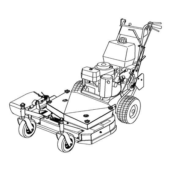
Page 1: Cutting Unit
Form No. 3353-989 Rev C Walk-Behind Mower Fixed Deck, Pistol Grip, Gear-Drive, with 32in Cutting Unit or 36in TURBO FORCE® Cutting Unit Model No. 30682—Serial No. 260000001 and Up Model No. 30684—Serial No. 260000001 and Up Register at www.Toro.com. Original Instructions (EN) -
Page 2: Table Of Contents
Important calls attention to special mechanical the product properly and safely. information and Note emphasizes general information worthy of special attention. You may contact Toro directly at www.Toro.com for product and accessory information, help finding a dealer, or to register your product. Contents... - Page 3 Adding Fuel ............13 Schematics ..............42 Think Safety First ..........14 Operating the Parking Brake and Neutral Locks ............. 14 Starting and Stopping the Engine ......15 Operating the Blade Control (PTO) Lever.............. 16 The Safety Interlock System........ 16 Driving Forward or Backward......
-
Page 4: Safety
Safety – Never remove gas cap or add fuel with engine running. Allow engine to cool before refueling. Do not smoke. Note: The addition of attachments made by – Never refuel or drain the machine indoors. other manufacturers that do not meet American National Standards Institute certification will cause •... -
Page 5: Toro Mower Safety
The following list contains safety information specific to Toro products and other safety information you must • Keep nuts and bolts tight, especially the blade know. - Page 6 • Use only genuine replacement parts to ensure that original standards are maintained. • Check brake operation frequently. Adjust and service as required.
-
Page 7: Slope Chart
Slope Chart... -
Page 8: Safety And Instructional Decals
Safety and Instructional Decals Safety decals and instructions are easily visible to the operator and are located near any area of potential danger. Replace any decal that is damaged or lost. 43-8480 95-5537 1. Read the Operator’s 3. Pull back to disengage Manual for instructions on operating the cutting blade 2. - Page 9 98-5130 1. Warning—read the Operator’s Manual for instructions on torquing the blade bolt/nut to 75-80 ft-lb (102-106 N⋅m). 106-2733 98-5954 1. Fast 3. Slow 2. Continuous variable setting 104-8569 105-4104 110-2067 1. Reverse 3. Transmission speeds 2. Neutral 36 inch Mowers Only 105-4111 110-2068 36 inch Mowers Only...
- Page 10 106-2737 1. Park 3. Neutral 5. Engine—run 2. Drive 4. Engine—stop 6. Warning—wear ear protection.
-
Page 11: Setup
• View the safety video. • Fill out the registration card and mail it in or register online at www.Toro.com. • Use the oil drain hose when changing the engine oil. Note: The cutting blades are set to a 3 inch (76mm) height-of-cut at initial purchase. -
Page 12: Product Overview
Throttle Control Product Overview The throttle control has two positions: Fast and Slow. Operator Presence Control (OPC) Levers When you squeeze the OPC levers against the handles, the OPC system senses that the operator is in the normal operating position. When you release the OPC levers, the OPC system senses that the operator has left the normal operating position, and the system will stop the engine if either the gear shift lever is not in the neutral... -
Page 13: Specifications
Authorized Service Dealer or Distributor or go to • Do not fill the fuel tank completely full. Add www.Toro.com for a list of all approved attachments gasoline to the fuel tank until the level is 1/4 and accessories. to 1/2 inch (6 to 13 mm) below the bottom of the filler neck. -
Page 14: Think Safety First
Important: Do not use fuel additives containing methanol or ethanol. In certain conditions during fueling, static Add the correct amount of gas electricity can be released causing a spark stabilizer/conditioner to the gas. which can ignite the gasoline vapors. A fire Note: A fuel stabilizer/conditioner is most or explosion from gasoline can burn you and effective when mixed with fresh gasoline. -
Page 15: Starting And Stopping The Engine
Releasing the Neutral Locks 1. Squeeze the drive levers back. Children or bystanders may be injured if they 2. Place your thumbs on the upper part of the locks move or attempt to operate the machine while and move them forward until they are in the drive it is unattended. -
Page 16: Operating The Blade Control (Pto) Lever
4. Disconnect the wire from the spark plug to prevent someone from accidentally starting the machine while transporting or storing it. 5. Close the fuel shut-off valve before transporting or storing the machine. Important: Close the fuel shut-off valve before transporting or the storing the machine to prevent fuel leakage. -
Page 17: Driving Forward Or Backward
Note: To go straight, release the drive levers • The machine is shifted into gear without holding the OPC levers. equally. To turn, squeeze the drive lever on the same side as the direction you want to turn. • The blade control (PTO) lever is engaged without holding the OPC levers. -
Page 18: Side Discharging Or Mulching The Grass
Side Discharging or Mulching the Grass This mower has a hinged grass deflector that disperses clippings to the side and down toward the turf. Without the grass deflector, discharge cover, or complete grass catcher assembly mounted in place, you and others are exposed to blade contact and thrown debris. - Page 19 2. Stop the engine and wait for all moving parts to stop before leaving the operating position. 3. Hold the blade bolt and remove the nut (Figure 10). Figure 11 1. Axle pivot bolt 2. Axle adjustment bolt 4. Place a jack under the rear center of the engine frame.
-
Page 20: Adjusting The Handle Height
3. Remove the lower bolts (3/8 x 1 inch) and flange nuts securing handle to rear frame (Figure 14). 4. Pivot the handle to the desired operating position and install the lower flange bolts (3/8 x 1 inch)and flange nuts into the mounting holes. Tighten all flange bolts. -
Page 21: Height Of Cut Chart
Height of Cut Chart Number of spacers Number of 1/4 inch blade spacers below spindle below caster 1/2 inch 3/16 inch (5 (13mm) Axle Position 1 inch (26 1–1/4 inch 1–1/2 inch 1–3/4 inch 2 inch (51 (32 mm) (38 mm) (45 mm) 1–1/8 inch 1–3/8 inch... -
Page 22: Maintenance
Maintenance Note: Determine the left and right sides of the machine from the normal operating position. Recommended Maintenance Schedule(s) Maintenance Service Maintenance Procedure Interval • Change the engine oil. After the first 8 hours • Check the mower belt tension. •... -
Page 23: Lubricating The Caster And Wheel Bearings
Greasing the Mower Belt Idler 3. Clean the grease fittings with a rag. Make sure to scrape any paint off the front of the fitting(s). Service Interval: Every 50 hours 4. Connect a grease gun to the fitting. Pump grease into the fittings until grease begins to ooze out of Grease the fitting on the mower belt idler arm pivot the bearings. -
Page 24: Engine Maintenance
Engine Maintenance Servicing the Air Cleaner Service Interval/Specification Foam element: Clean it after every 25 operating hours. Paper element: Check it after every 50 operating hours. Replace it after every 200 operating hours or yearly, which ever comes first. Inspect the foam and paper elements and replace them if they are damaged or excessively dirty. -
Page 25: Servicing The Engine Oil
Installing the Foam and Paper Elements 4. Clean around the oil dipstick (Figure 20) so that dirt cannot fall into the filler hole and damage the engine. Important: To prevent engine damage, always operate the engine with the complete foam and paper air cleaner assembly installed. -
Page 26: Servicing The Spark Plugs
Figure 22 1. Oil filter 2. Adapter 3. Apply a thin coat of new oil to the rubber gasket on the replacement filter (Figure 22). 4. Install the replacement oil filter to the filter adapter, Figure 21 turn the oil filter clockwise until the rubber gasket contacts the filter adapter, then tighten the filter an 1. -
Page 27: Installing The Spark Plugs
Important: Always replace the spark plugs when it has a black coating, worn electrodes, an oily film, or cracks. 3. Check the gap between the center and side electrodes (Figure 24). Bend the side electrode (Figure 24) if the gap is not correct. Installing the Spark Plugs 1. -
Page 28: Fuel System Maintenance
Fuel System Maintenance Servicing the Fuel Tank In certain conditions, gasoline is extremely flammable and highly explosive. A fire or explosion from gasoline can burn you and others and can damage property. Figure 25 • Drain gasoline from the fuel tank when the 1. -
Page 29: Drive System Maintenance
Drive System Maintenance Checking the Tire Pressure Service Interval: Every 50 hours Maintain the air pressure in the front and rear tires as specified. Check the pressure at the valve stem after every 50 operating hours or monthly, whichever occurs first (Figure 27). -
Page 30: Cooling System Maintenance
Cooling System Maintenance Cleaning the Air Intake Screen Service Interval: Before each use or daily Before each use remove any build-up of grass, dirt or other debris from the cylinder and cylinder head cooling fins, air intake screen on flywheel end, and carburetor-governor levers and linkage. -
Page 31: Brake Maintenance
Brake Maintenance Servicing the Brakes Before each use, check brakes on both a level surface and slope. Always set the parking brake when you stop the machine or leave it unattended. If the parking brake does not hold securely, an adjustment is required. Checking the Brakes Figure 29 Service Interval: Before each use or daily... -
Page 32: Belt Maintenance
Belt Maintenance 4. Remove the mower belt (Figure 31). Checking the Belts Service Interval: Every 50 hours Check all belts after every 50 operating hours or monthly, whichever occurs first. Look for dirt, wear, cracks and signs of overheating. Replacing the Traction Drive Belt 1. -
Page 33: Adjusting The Mower Belt Tension
Note: The proper mower belt tension is 10-15 lbf. 12. Disengage the blade control (PTO) lever. (44-67 N) with the belt deflected 1/2 inch (13 mm) Note: If the assist arm does not contact the front halfway between the pulleys (Figure 32). stop on the mower deck (Figure 34), adjust the clevis to bring the bell crank closer to the transmission output shaft (Figure 33). -
Page 34: Controls System Maintenance
Controls System Important: The belt must be tight enough to not slip during heavy loads while cutting grass. Over Maintenance tensioning the belt will reduce the bearing life of the belt and the spindle. 1. Disengage the blade control (PTO) lever and set the Adjusting the Control Rods parking brakes. -
Page 35: Mower Deck Maintenance
Mower Deck Maintenance Servicing the Cutting Blades To ensure a superior quality of cut, keep the blades sharp. For convenient sharpening and replacement, you may want to keep extra blades on hand. Figure 36 A worn or damaged blade can break, and a piece of the blade could be thrown into the 1. -
Page 36: Removing The Blades
To ensure optimum performance and continued safety conformance of Figure 38 the machine, use genuine Toro replacement blades. Replacement blades made by other manufacturers may result in non-conformance with safety standards. 2. Measure from a level surface to the cutting edge, position A, of the blades (Figure 39). -
Page 37: Adjusting The Blade Brake
the end of the sail area only (Figure 42). Repeat this procedure until the blade is balanced. Figure 42 1. Blade 2. Balancer Installing the Blades 1. Place the blade onto the bolt and over the curved washer. Select the proper number of spacer(s) for the height-of- cut, and slide the bolt into the spindle (Figure 40). -
Page 38: Replacing The Grass Deflector
Figure 43 1. Spring mounting bolts 3. 1/8-3/16 inch (3mm-5mm) 2. Blade brake pad Figure 44 Replacing the Grass Deflector 1. Bolt 5. Spring installed 2. Spacer 6. Grass Deflector 3. Locknut 7. L end of spring, place behind deck edge before installing bolt 4. -
Page 39: Storage
Storage 10. Check and tighten all bolts, nuts, and screws. Repair or replace any part that is damaged or defective. 11. Paint all scratched or bare metal surfaces. Paint is Cleaning and Storage available from your Authorized Service Dealer. 1. Disengage the power take off (PTO), set the parking 12. -
Page 40: Troubleshooting
Troubleshooting Problem Possible Cause Corrective Action Engine will not start, starts hard, or fails 1. Fuel tank is empty. 1. Fill the fuel tank with gasoline. to keep running. 2. Fuel shut off valve is closed. 2. Open the fuel shut off valve. 3. - Page 41 Problem Possible Cause Corrective Action Blades do not rotate. 1. Mower deck belt is worn or loose. 1. Check the belt tension. 2. Mower deck belt is broken. 2. Install a new deck belt. 3. Mower deck belt is off pulley. 3.
- Page 42 Schematics Electrical Schematic (Rev. -)
- Page 44 Countries Other than the United States or Canada Customers who have purchased Toro products exported from the United States or Canada should contact their Toro Distributor (Dealer) to obtain guarantee policies for your country, province, or state. If for any reason you are dissatised with your Distributor’s service or have difculty obtaining guarantee information, contact the Toro importer.
Need help?
Do you have a question about the 30682 and is the answer not in the manual?
Questions and answers