Toro Groundsmaster 4000 Operator's Manual
Hide thumbs
Also See for Groundsmaster 4000:
- Operator's manual (88 pages) ,
- Operator's manual (76 pages) ,
- Operator's manual (64 pages)

Related Manuals for Toro Groundsmaster 4000


Summary of Contents for Toro Groundsmaster 4000
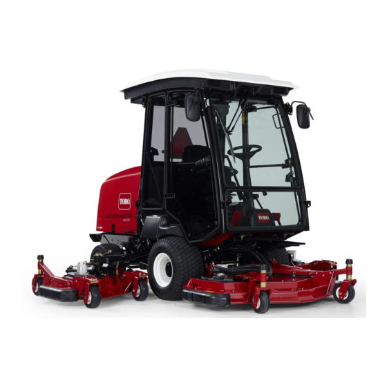
- Page 1 Form No. 3420-868 Rev A Groundsmaster ® 4000 or 4010 Rotary Mower Model No. 30605—Serial No. 401420001 and Up Model No. 30635—Serial No. 401420001 and Up *3420-868* A Register at www.Toro.com. Original Instructions (EN)
- Page 2 Whenever you need service, genuine Toro parts, or additional information, contact an Authorized Service Dealer or Toro Customer Service and have the model and serial numbers of your product ready. Figure 1 identifies the location of the model and serial numbers ©...
-
Page 3: Table Of Contents
Contents Recommended Maintenance Schedule(s) ... 43 Daily Maintenance Checklist......45 Pre-Maintenance Procedures ......46 Safety ............... 4 Maintenance Safety.......... 46 General Safety ........... 4 Removing the Hood .......... 46 Engine-Emission Certification......4 Lubrication ............47 Safety and Instructional Decals ......5 Greasing the Bearings and Bushings .... -
Page 4: Safety
Safety Cleaning the Cab Pre-Filter ......71 Cleaning the Air-Conditioning Assembly ..............71 This machine has been designed in accordance with Storage ..............72 EN ISO 5395:2013 and ANSI B71.4-2017 with the CE Preparing for Seasonal Storage......72 Kit installed, per the Declaration of Conformity. General Safety This product is capable of amputating hands and feet and of throwing objects. -
Page 5: Safety And Instructional Decals
Safety and Instructional Decals Safety decals and instructions are easily visible to the operator and are located near any area of potential danger. Replace any decal that is damaged or missing. decalbatterysymbols Battery Symbols decal100-5622 Some or all of these symbols are on your battery 100-5622 1. - Page 6 decal100-5693 decal104-3579 100-5693 104-3579 1. Height-of-cut adjustment 1. Low height-of-cut 2. High height-of-cut adjustment adjustment decal106-6754 decal100-5694 106-6754 100-5694 1. Warning—do not touch the hot surface. 1. Height-of-cut adjustment 2. Cutting/dismemberment hazard, fan and entanglement hazard, belt—stay away from moving parts. decal100-6578 100-6578 1.
- Page 7 decal114-0846 114-0846 1. Read the Operator’s Manual for information on starting the engine—1) Set to neutral; 2) Engage the brake; 3) Set the engine speed to slow; 4) Turn the key to preheat; 5) Turn the key to start the engine. 2.
- Page 8 decal117-4765 117-4765 1. Read the Operator's Manual. 2. Do not use starting aids. decal120-0250 120-0250 1. Slow-moving vehicle...
- Page 9 decal120-6604 120-6604 1. Thrown object hazard—keep bystanders away from the machine. 2. Cutting/dismemberment hazard of hand, mower blade—stay away from moving parts, keep all guards and shields in place. decal120-8947 3. Cutting/dismemberment hazard of foot, mower blade—stay 120-8947 away from moving parts, keep all guards and shields in place.
- Page 10 decal121-3887 121–3887 1. Read the Operator’s Manual. decal121-8378 121-8378 Model with Cab Only 1. Fan (off) 3. Cold air 5. External air 7. Air conditioner (off) 4. Hot air 6. Internal air 2. Fan (on full) 8. Air conditioner (on) decal125-9688 125-9688 Model with Cab Only...
- Page 11 decal130-0611 130-0611 Model with Cab Only 1. Warning—1) Remove the pin; 2) Raise the doors; 3) Exit the cab. decal127-3700 127-3700 1. Raise the left deck. 4. Lock the engine speed. decal130-5355 130-5355 2. Raise the center deck. 5. Unlock the engine speed. 3.
- Page 12 decal130-6043 130-6043 1. Read the Operator’s Manual.
- Page 13 decal130-6046 130-6046 1. Read the Operator’s Manual.
- Page 14 decal133-5618 133-5618 decal132-3600 132-3600 Model with Cab Only 1. Read the Operator's 5. Working light (20 A) Manual for more information on fuses. 2. Headlight (25 A) 6. Auxiliary power (15 A) 3. Condenser fan and A/C 7. Cab light (15 A) clutch (30 A) 4.
-
Page 15: Setup
Setup Loose Parts Use the chart below to verify that all parts have been shipped. Procedure Description Qty. – No parts required Grease the machine. Media and Additional Parts Description Qty. Operator's Manual Review before operating the machine. Engine owner’s manual Use to reference engine information. - Page 16 Traction Pedal To stop the machine, reduce your foot pressure on the traction pedal and allow it to return to the center position (Figure Brake Pedals There are 2 foot pedals that operate individual wheel brakes for turning assistance, parking, and to aid in better side-hill traction.
- Page 17 Note: The decks do not lower while in the high-speed range and they do not raise or lower if you are out of the seat while the engine is running. Also, the decks lower with the key in the O position and you are in the seat.
-
Page 18: Cab Controls
Cab Controls Windshield Latch Lift up the latches to open the windshield (Figure 8). Press in the latch to lock windshield to the O position. Pull out and down on the latch to close and secure the windshield. g032672 Figure 7 g196911 Figure 8 1. - Page 19 Using the InfoCenter Control InfoCenter Icon Description SERVICE DUE Indicates when scheduled service The InfoCenter LCD display shows information about should be performed your machine, such as the operating status, various diagnostics and other information about the machine Engine rpm/status—indicates the engine rpm (Figure 9).
- Page 20 InfoCenter Icon Description (cont'd.) InfoCenter Icon Description (cont'd.) Denied or not allowed Operator should change to the indicated state Engine Start Symbols are often combined to form sentences. Some PTO—indicates that the PTO is on examples are shown below Stop or shutdown Operator should put the machine in neutral Engine...
- Page 21 Controls the units used on the faults. Refer to the Service InfoCenter; the menu choices Manual or your Authorized are English or Metric Toro Distributor for more Language Controls the language used information on the Faults menu and the information on the InfoCenter* contained there.
- Page 22 The factory default PIN code for you machine is either 0000 or 1234. If you changed the PIN code and forgot the code, contact your authorized Toro distributor for assistance. From the M , use the center button to scroll down to the S...
- Page 23 Setting the Auto Idle In the Settings Menu, scroll down to Auto Idle. Press the right button to change the auto idle time between O , 8S, 10S, 15S, 20S, and 30S. Setting the Maximum Allowed Mow Speed • In the Settings Menu, Scroll down to Mow Speed and press the right button.
-
Page 24: Specifications
Specifications Note: Specifications and design are subject to change without notice. g197050 Figure 12... -
Page 25: Attachments/Accessories
Contact your Authorized Service Dealer or authorized Toro Before Operation distributor or go to www.Toro.com for a list of all approved attachments and accessories. To ensure optimum performance and continued safety Before Operation Safety certification of the machine, use only genuine Toro replacement parts and accessories. -
Page 26: Checking The Engine-Oil Level
• Before mowing, always inspect the machine to minimum cetane rating should be 40. Purchase fuel in ensure that the blades, blade bolts, and cutting quantities that can be used within 180 days to ensure assemblies are in good working condition. fuel freshness. -
Page 27: Checking The Tire Pressure
Adding Fuel g001055 Figure 14 Checking the Torque of the Wheel Lug Nuts Service Interval: After the first hour After the first 10 hours Every 200 hours Torque the wheel lug nuts to 115 to 136 N∙m (85 to 100 ft-lb) in the order shown in Figure 15 Figure... -
Page 28: Checking The Planetary-Gear-Drive Oil
Checking the Rear-Axle WARNING Lubricant Failing to maintain proper torque of the wheel lug nuts could result in personal injury. Service Interval: Every 400 hours Torque the wheel lug nuts to the proper torque The rear axle is filled with SAE 85W-140 gear lube. value. -
Page 29: Adjusting The Roll Bar
Lowering the Roll Bar Important: Lower the roll bar only when necessary. Important: Ensure that the seat is secured with the seat latch. g011488 Figure 19 1. Gearbox 2. Check/fill plug Adjusting the Roll Bar g221650 Figure 20 WARNING To avoid injury or death from rollover: keep Raising the Roll Bar the roll bar in the raised locked position and use the seat belt. - Page 30 Park the machine on a level surface. Start the engine and raise the mower decks to change height of cut. Shut off the engine, engage the parking brake, and remove the key from the ignition after the mower deck is raised. Position the caster-wheel axles in the same holes in all caster forks.
- Page 31 Note: When using 25 mm (1 inch), 38 mm (1-1/2 inches), or 51 mm (2 inches) heights of cut, move the skids and gauge wheels to the highest position. Side Mower Decks To adjust the height of cut on the side mower decks, add or remove an equal number of spacers from the caster forks, position the caster-wheel axles in the high or low height-of-cut holes in the caster forks, and...
-
Page 32: Adjusting The Skids
Adjusting the Skids Insert the clevis pins and install the hairpin cotters. Mount the skids in the lower position when operating Rotate the tension rod counterclockwise (finger at heights of cut greater than 64 mm (2-1/2 inches) tight) to put tension on adjustment. and in the higher position when operating at heights Remove the hairpin cotters and clevis pins of cut lower than 64 mm (2-1/2 inches). -
Page 33: Adjusting The Mower-Deck Rollers
Adjusting the Mower-Deck Lower the mower decks onto a flat surface and remove the covers from the top of the mower Rollers decks. Loosen the flange nut, securing the idler pulley, The mower-deck rollers should be mounted in the to release the belt tension on each mower deck. lower position when operating at height of cuts greater than 64 mm (2-1/2 inches), and in the higher position when operating in height of cuts lower than 64 mm... - Page 34 Setting Up the Side Mower Decks Rotate the blade of each spindle until the ends Note: It is best to use the Toro tool (Part No. face forward and backward. 121-3874) to tighten the tensioning cap. Measure from the floor to the front tip of the Rotate the blade on each spindle until the ends cutting edge.
-
Page 35: Checking The Safety-Interlock Switches
Checking the Note: If adjustments need to be made to match the cut between the front and side mower decks, Safety-Interlock Switches make the adjustments to the side mower decks only. Service Interval: Before each use or daily If the inside edge of the side mower deck is too high relative to the outside edge of the front The machine has interlock switches in the electrical mower deck, remove a shim from the bottom of... -
Page 36: Aiming The Headlights
80dBA with a K-factor of 1.0 dBA, when evaluated per EN ISO 5395:2013-1 Annex F. • Never leave a running machine unattended. Contact your authorized Toro distributor to set the • Before leaving the operating position (including machine software to activate Quiet Mode. -
Page 37: Starting The Engine
The machine could device. suddenly roll over if a wheel goes over the edge • A cab installed by Toro is a roll bar. or the edge caves in. Establish a safety area between the machine and any hazard. •... -
Page 38: Shutting Off The Engine
starter failure may result. If the engine fails the rear screen and lowers the engine-coolant and to start after 30 seconds, turn the key to hydraulic-fluid temperatures. the O position, check the controls and You can complete a manually-initiated reverse cycle procedures, wait 30 additional seconds, and by simultaneously pressing the right and left buttons repeat the starting procedure. -
Page 39: Adjusting The Transport Speed
Refer to Setting the Maximum Allowed Mow Speed With Toro Smart Power™, you do not need to (page 23) for the procedure to set the mow speed. listen to the engine speed in heavy load conditions. Smart Power prevents the engine from bogging... -
Page 40: Operating Tips
Operating Tips Resolving After-Cut Appearance Reference the After-cut Appearance Troubleshooting Operating the Machine Guide available at www.Toro.com. • Start the engine and run it at the position HALF IDLE Using Proper Mowing Techniques until it warms up. Move the engine-speed switch... -
Page 41: After Operation
Pushing or Towing the and damage to the seals and bearings caused by excessive water pressure. Ensure that the Machine radiator and oil cooler are kept free of dirt or grass clippings. After cleaning, inspect the machine for In an emergency, you can move the machine possible hydraulic-fluid leaks, damage, or wear to the forward by actuating the bypass valve in the hydraulic and mechanical components, and check the... -
Page 42: Locating The Jacking Points
between ports M8 and P2 on the rear traction manifold (located behind the front tire). The hose assembly includes 1 hose (Part No. 95-8843), 2 coupler fittings (Part No. 95-0985), and 2 hydraulic fittings (Part No. 340-77). Locating the Jacking Points DANGER Mechanical or hydraulic jacks may fail to support machine and cause a serious injury. -
Page 43: Maintenance
Important: Refer to your engine owner’s manual for additional maintenance procedures. Note: Download a free copy of the electrical or hydraulic schematic by visiting www.Toro.com and searching for your machine from the Manuals link on the home page. Note: Determine the left and right sides of the machine from the normal operating position. - Page 44 Maintenance Service Maintenance Procedure Interval • Drain and clean the fuel tank. (also if the fuel system is contaminated). • Change the front planetary-gear oil or yearly, whichever comes first. • Change the rear-axle oil. • Check the rear wheel toe-in. •...
-
Page 45: Daily Maintenance Checklist
Daily Maintenance Checklist Duplicate this page for routine use. For the week of: Maintenance Check Item Monday Tuesday Wednesday Thursday Friday Saturday Sunday Check the safety-interlock operation. Check the brake operation. Check the engine-oil level. Check the cooling-system-fluid level. Drain the water/fuel separator. -
Page 46: Pre-Maintenance Procedures
Pre-Maintenance Removing the Hood Procedures Unlatch and raise the hood. Remove the hairpin cotter securing the hood pivot to the mounting brackets (Figure 40). Maintenance Safety • Before adjusting, cleaning, repairing, or leaving the machine, do the following: – Park the machine on a level surface. –... -
Page 47: Lubrication
Lubrication Greasing the Bearings and Bushings Service Interval: Every 50 hours—Lubricate all of the bearings and bushings. Every 500 hours/Yearly (whichever comes first) The machine has grease fittings that you must lubricate regularly with No. 2 lithium grease. Also, lubricate the machine immediately after every washing. - Page 48 g017810 Figure 44 g011557 Front Lift Assemblies Figure 47 • 2 (each side) lift-arm-cylinder bushings (Figure • 2 lift-arm-ball joints (Figure Side Lift Assemblies • 6 main lift-arm bushings (Figure 48 Figure • 2 bell-crank-pivot bushings (Figure • 4 rear arm bushings (Figure •...
-
Page 49: Engine Maintenance
Alternate oil: SAE 10W-30 or 5W-30 (all g011555 Figure 51 temperatures) Toro Premium Engine Oil is available from your authorized Toro distributor in either 15W-40 or 10W-30 viscosity grades. See the Parts Catalog for part numbers. Checking the Engine-Oil Level Service Interval: Before each use or daily The engine is shipped with oil in the crankcase;... - Page 50 Check the engine-oil level; refer to Figure g033183 Figure 52 g033165 Figure 53 Note: When using different oil, drain all old oil from the crankcase before adding new oil. Add oil to the crankcase. Crankcase Oil Capacity Approximately 5.7 L (6 US qt) with the filter. Changing the Engine Oil and Filter Service Interval: After the first 50 hours Every 250 hours...
-
Page 51: Servicing The Air Cleaner
Servicing the Air Cleaner Service Interval: Before each use or daily—Check the air-cleaner indicator. Every 50 hours—Inspect the air cleaner. Every 400 hours—Service the air cleaner (earlier if the air cleaner indicator shows red, and more frequently in extremely dirty or dusty conditions). -
Page 52: Fuel System Maintenance
Fuel System Maintenance Servicing the Fuel System Draining the Fuel Tank Service Interval: Every 800 hours—Drain and clean g011505 the fuel tank. (also if the fuel system Figure 56 is contaminated). 1. Air-cleaner safety filter Drain and clean the tank also if the fuel system becomes contaminated or if you are storing the Reset the indicator (Figure... -
Page 53: Servicing The Fuel Filter
Servicing the Fuel Filter Service Interval: Every 400 hours Clean the area around the fuel-filter head (Figure 58). g021291 Figure 58 1. Fuel-filter head 2. Fuel filter Remove the filter and clean the filter head mounting surface (Figure 58). Lubricate the filter gasket with clean lubricating engine oil;... -
Page 54: Electrical System Maintenance
Rinse with clear water. Coat the battery posts and terminals to touch any metal parts of cable connectors with Grafo 112X (skin-over) grease the machine. (Toro Part No. 505-47) or petroleum jelly to prevent • Do not allow metal tools to short corrosion. between the battery terminals and Open the battery cover on the side of the shroud metal parts of the machine. -
Page 55: Locating The Fuses
Figure 65). Coat both battery connections with Grafo 112X Note: Cab model only (skin-over) grease, Toro Part No. 505-47, petroleum jelly, or light grease to prevent corrosion. Slide the rubber boot over the positive terminal. Close the battery cover. Locating the Fuses... -
Page 56: Drive System Maintenance
Drive System Maintenance Adjusting the Traction-Pedal Angle You can adjust the operating angle of the traction g008862 pedal for your comfort. Figure 67 Loosen the 2 nuts and bolts securing the left side 1. Check/drain plug of the traction pedal to the bracket (Figure 66). -
Page 57: Changing The Rear-Axle Oil
Changing the Rear-Axle Oil Add enough oil to bring the level up to the bottom of the check plug holes; refer to Changing the Planetary-Gear-Drive Oil (page 56). Service Interval: After the first 200 hours Install the plugs. Every 800 hours Position the machine on a level surface. -
Page 58: Cooling System Maintenance
Cooling System Important: Do not use water only or alcohol/methanol based coolants, as this Maintenance may cause damage. Install the radiator cap and expansion-tank cap. Cooling System Safety • Swallowing engine coolant can cause poisoning; keep out of reach from children and pets. •... -
Page 59: Servicing The Engine-Cooling System
Servicing the Brake Maintenance Engine-Cooling System Adjusting the Service Service Interval: Every 100 hours Brakes Every 2 years Remove debris from the oil radiator/oil cooler Adjust the service brakes when there is more than daily. Clean them more frequently in dirty conditions. 25 mm (1 inch) of free travel of the brake pedal, or when the brakes do not work effectively. -
Page 60: Belt Maintenance
Belt Maintenance Tensioning the Blade-Drive Belts Servicing the Alternator Service Interval: After the first 10 hours Belt Every 50 hours Service Interval: After the first 10 hours When properly tensioned, the inside measurement Every 100 hours of the extension spring (hook to hook) should be approximately 8.3 to 9.5 cm (3-1/4 to 3-3/4 inches). -
Page 61: Hydraulic System Maintenance
Toro distributor for part numbers). the motor to the mower deck with the bolts previously removed. Alternative fluids: If the Toro fluid is not available, Note: other conventional, petroleum-based fluids may be Ensure that the belt is positioned on the... - Page 62 (not an ashless-type fluid). Toro Synthetic Biodegradable Hydraulic Fluid (Available in 19 L (5 US gallon) pails or 208 L (55 US gallon) drums. See the Parts Catalog or your Toro Distributor for part numbers) This high quality synthetic, biodegradable fluid has been tested and found compatible for this Toro model.
- Page 63 Service Interval: After the first 200 hours Service Interval: Every 2 years Every 800 hours Inspect the hydraulic lines and hoses daily for Use the following Toro replacement filters: leaks, kinked lines, loose mounting supports, wear, loose fittings, weather deterioration, and chemical •...
-
Page 64: Cutting Unit Maintenance
Adjusting the Counterbalance Cutting Unit Maintenance Pressure Pivoting (Tilting) the Front The counterbalance test port is used to test the pressure in the counterbalance circuit (Figure 80). Mower Deck to the Upright The recommended counterbalance pressure is 2241 kPa (325 psi). To adjust the counterbalance Position pressure, loosen the locknut, rotate the adjusting screw... -
Page 65: Pivoting The Front Mower Deck Down
Pivoting the Front Mower Deck Down With the help of another person, hold the mower deck upright, remove the hairpin cotter securing the cable end, and remove the cable from the pin. Pivot (tilt) the mower deck downward. Store the cable under the operator's platform. Sit on the seat, start the engine, and lower the g011490 mower deck until it is slightly off the floor. -
Page 66: Servicing The Caster-Arm Bushings
Servicing the Caster-Arm Servicing the Caster Bushings Wheels and Bearings Service Interval: Every 800 hours Removing the Bushings Remove the locknut from the bolt holding the caster-wheel assembly between the caster fork The caster arms have bushings pressed into the (Figure 85) or the caster-pivot arm (Figure... -
Page 67: Blade Maintenance
Blade Maintenance To assemble the caster wheel, push the bearing into the wheel hub. Note: When installing the bearings, press on Blade Safety the outer face of the bearing. Slide the bearing spacer into the wheel hub and A worn or damaged blade can break, and a piece of push the other bearing into the open end of the the blade could be thrown toward you or bystanders, wheel hub to captivate the bearing spacer inside... -
Page 68: Removing And Installing The Mower Blade(S)
Replace the blade if it hits a solid object, is out of Both cutting edges and the sail, which is the turned-up balance, or if it is bent. Always use genuine Toro portion opposite of the cutting edge, contribute to replacement blades to ensure safety and optimum a good quality of cut. -
Page 69: Correcting A Mower-Deck Mismatch
Note: Remove the blades and sharpen them on a grinder. After sharpening the cutting edges, install the blade with the anti-scalp cup and blade bolt; refer to Removing and Installing the Mower Blade(s) (page 68). Correcting a Mower-Deck Mismatch When there is mismatch between the blades on a single mower deck, the grass appears streaked when it is cut. -
Page 70: Cab Maintenance
Cab Maintenance Cleaning the Cab Important: Use care around the cab seals and lights (Figure 91). If you are using a pressure washer, keep the washer wand at least 0.6 m (2 ft) away from the machine. Do not use the pressure washer directly on the cab seals and lights or under the rear overhang. - Page 71 Cleaning the Cab Pre-Filter The purpose of the cab pre-filter is to prevent large debris, such as grass and leaves, from entering the cab filters. Rotate the screen cover down. Clean the filter with water. Note: Do not use a pressure washer. Important: If the filter has a hole, tear, or other damage, replace the filter.
- Page 72 Clean the battery, terminals, and posts with a wire brush and baking soda solution. Coat the cable terminals and battery posts with Grafo 112X skin-over grease (Toro Part No. 505-47) or petroleum jelly to prevent corrosion. Slowly recharge the battery every 60 days for 24 hours to prevent lead sulfation of the battery.
- Page 73 Notes:...
- Page 74 While the exposure from Toro products may be negligible or well within the “no significant risk” range, out of an abundance of caution, Toro has elected to provide the Prop 65 warnings. Moreover, if Toro does not provide these warnings, it could be sued by the State of California or by private parties seeking to enforce Prop 65 and subject to substantial penalties.
- Page 75 The Way Toro Uses Information Toro may use your personal information to process warranty claims, to contact you in the event of a product recall and for any other purpose which we tell you about. Toro may share your information with Toro's affiliates, dealers or other business partners in connection with any of these activities. We will not sell your personal information to any other company.
- Page 76 Countries Other than the United States or Canada Customers who have purchased Toro products exported from the United States or Canada should contact their Toro Distributor (Dealer) to obtain guarantee policies for your country, province, or state. If for any reason you are dissatisfied with your Distributor's service or have difficulty obtaining guarantee information, contact the Toro importer.
Need help?
Do you have a question about the Groundsmaster 4000 and is the answer not in the manual?
Questions and answers