Toro LT3340 Operator's Manual
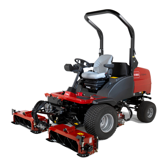
Heavy-duty triple turf mower traction unit
Hide thumbs
Also See for LT3340:
- Operator's manual (64 pages) ,
- Installation instructions manual (28 pages) ,
- Addendum (4 pages)

Subscribe to Our Youtube Channel
Related Manuals for Toro LT3340


Summary of Contents for Toro LT3340
- Page 1 Form No. 3410-813 Rev B LT3340 Heavy-Duty Triple Turf Mower Traction Unit Model No. 30657—Serial No. 400000000 and Up *3410-813* B Register at www.Toro.com. Original Instructions (EN)
- Page 2 Whenever you need service, genuine Toro parts, or additional information, contact an Authorized Service Dealer or Toro Customer Service and have the model and serial numbers of your product ready. Figure 1 identifies the location of the model and serial numbers on the product.
-
Page 3: Table Of Contents
Contents Checking the Fuel Lines and Connections..........36 Bleeding the Fuel System ......... 36 Safety ............... 4 Replacing the Fuel Filter ........36 General Safety........... 4 Electrical System Maintenance ......37 Safety and Instructional Decals ......4 Electrical System Safety ........37 Setup ................ -
Page 4: Safety
Safety • Do not operate the machine without all guards and other safety protective devices in place and functioning properly on the machine. This machine has been designed in accordance with • Keep children, bystanders, and pets out of the EN ISO 5395. - Page 5 decal111-3562 111-3562 1. Press the pedal to adjust the steering wheel angle. decal111-3277 111-3277 1. Horn 5. Fast decal111-3566 2. Cutting units—lower/float 6. Engine speed 111-3566 3. Cutting units—hold 7. Slow 1. Falling, crushing hazard—ensure that the operator platform 4. Cutting units—raise latch is engaged before operating.
- Page 6 decal111-7249 111-7249 1. Daily service interval 6. Check hydraulic fluid level 11. Check cutting unit setting 16. Lubrication points for daily interval 2. 50 hour service interval 7. Check fuel level 12. Check engine coolant level 17. Lubrication points for 50 hour interval 3.
- Page 7 decal111-5007 111-5007 Note: This machine complies with the industry standard stability test in the static lateral and longitudinal tests with the maximum recommended slope indicated on the decal. Review the instructions for operating the machine on slopes in the Operator’s Manual as well as the conditions in which you would operate the machine to determine whether you can operate the machine in the conditions on that day and at that site.
-
Page 8: Setup
Setup Media and Additional Parts Description Qty. Operator's Manual Read the manuals before operating the machine. Engine operator’s manual CE certificate The certificate indicates CE compliance. Product Overview Store all documentation in a safe place for future use. Note: Determine the left and right sides of the machine from the normal operating position. -
Page 9: Controls
Controls Control Panel Components g014419 Figure 5 1. Weight transfer control Braking System Parking Brake Move the parking brake switch to the forward position by pressing the smaller locking button and moving the switch forward to engage the parking brake (Figure Note: Do not operate the mower with the parking... - Page 10 Service Brake Travel Service braking is achieved by the hydraulic Forward travel: Press the forward travel pedal to transmission system. When the forward or reverse increase forward travel speed. Release the pedal to travel pedals are released or the engine speed is reduce speed (Figure reduced, service braking becomes effective and travel...
- Page 11 Differential Lock Adjustable Steering Column WARNING WARNING The turning radius increases when the Never operate the machine without first differential lock is engaged. Using the checking that the steering column adjuster differential lock at high speed may lead to loss mechanism is in good working order and that, of control and cause serious injury and/or once adjusted and locked, the steering wheel...
- Page 12 Operator Seat • Operator weight adjustment: Rotate the handle clockwise to increase suspension stiffness and counterclockwise to decrease the stiffness. The WARNING dial indicates when the optimum suspension Never operate the mower without first adjustment has been set according to operator checking that the operator seat mechanisms weight (kg);...
- Page 13 • • Height adjustment: Manually lift the seat for Backrest adjustment: Pull the handle outward to incremental height adjustment. To lower the seat, adjust the seat backrest angle. Release the handle lift it beyond the highest setting, then allow it to to lock the seat backrest in position (Figure 14).
- Page 14 Warning Systems Low Battery Charge Warning Light The battery charge warning light illuminates when low Engine Coolant Overheating Warning Light battery charge occurs (Figure 17). The engine coolant warning light illuminates, the horn is actuated and the cutting units stop (Figure 15).
- Page 15 g014558 g014555 Figure 22 Figure 19 1. Horn Hour Meter Key Switch The hour meter shows the total hours that the machine has been operated (Figure 23). 0 = Engine off I = Engine run/Auxiliary on II = Engine pre-heat III = Engine start g014559 Figure 23...
-
Page 16: Specifications
Contact your Authorized Service Dealer or authorized Toro distributor or go to www.Toro.com for a list of all approved attachments and accessories. To ensure optimum performance and continued safety certification of the machine, use only genuine Toro replacement parts and accessories. -
Page 17: Before Operation
Performing Daily Operation Maintenance Before Operation Service Interval: Before each use or daily Before starting the machine each day, perform the Each Use/Daily procedures listed in Maintenance Before Operation Safety (page 29). General Safety Filling the Fuel Tank • Never allow children or untrained people to operate or service the machine. -
Page 18: During Operation
Install fuel-tank cap tightly after filling tank. – Park the machine on a level surface. – Disengage the cutting unit(s) and lower the Note: If possible, fill the fuel tank after each use. attachments. This minimizes possible buildup of condensation inside the fuel tank. -
Page 19: Using The Operator Platform Latching Mechanism
Releasing the Platform • Review the slope instructions listed below for operating the machine on slopes and review the Move the locking latch handle towards the front conditions in which you will operate the machine of the mower until the latch hooks clear the to determine whether you can operate it in the locking bar. -
Page 20: Understanding The Operator Presence Controls
Securing the Platform to the cutting units is automatically disengaged. To engage the drive to the cutting units, the operator Lower the platform carefully. must return to the seat, then operate the cutting unit drive switch to the Off position before moving it back Note: The gas spring will provide assistance. -
Page 21: Checking The Interlock Switches
• Keep all nuts, bolts, and screws correctly torqued ensure that the equipment is in safe working condition. • Replace worn or damaged parts for safety. • Ensure that the seat belt and mountings are in safe working order. • Wear the seat belt when the roll bar is raised and no seat belt when the roll bar is lowered. -
Page 22: Starting The Engine
should not start when the ignition key is turned. Turn the key to the on position I and check Repeat for the reverse position. that the engine oil pressure and battery charge warning lights illuminate. Checking the Parking Brake If the engine is cold, turn the key to the preheat position II so that the pre-heat indicator light is Interlock Switch (Figure... -
Page 23: Using The Grass Deflectors
Controlling the Position of the Individual Cutting units The cutting units may be raised or lowered independently using the bank of 3 lift control switches. To lower the cutting units, operate the lift control switches in a downward direction and release. The cutting unit drive switch must be on (forward) to do this, the reel drive will engage when the cutting units are approximately 150... -
Page 24: Engaging The Cutting Unit Drive
Engaging the Cutting Unit Drive g014434 Figure 31 1. Forward 3. Reverse 2. Off The cutting unit drive can be engaged only when the operator is seated correctly, refer to Checking the Operator Presence Seat Switch (page 21). Forward rotation cutting unit drive engagement: Press the top of the cutting unit drive switch to the forward position (Figure... -
Page 25: Using Weight Transfer / Traction Assistance
Engage the parking brake and disengage all drives. Lower the cutting units to the ground or securely lock them in the designated transport positions. Shut off the engine and remove the ignition key to isolate all power sources and ensure that they are stopped. -
Page 26: After Operation
Maximizing the Quality of Cut After Operation The quality of cut will deteriorate if the forward speed is excessive. Always balance the quality of cut with After Operation Safety the work rate required and set the forward speed accordingly. General Safety •... -
Page 27: Hauling The Machine
Hauling the Machine Important: Do not tow the machine faster than 3 to 5 km/h (2 to 3 mph), otherwise internal • Use full-width ramps for loading the machine onto transmission damage may occur. a trailer or truck. Decommission the front wheel motor disc brakes •... - Page 28 Tighten the setscrew into the threaded hole Identify the right front wheel motor disc in the brake piston until the brake is released brake assembly. (Figure 36). Rotate the setscrew counterclockwise and Identify the left front wheel motor disc brake remove together with the washer.
-
Page 29: Maintenance
• To ensure safe, optimal performance of the – Shut off the engine and remove the key. machine, use only genuine Toro replacement – Wait for all moving parts to stop. parts. Replacement parts made by other – Allow machine components to cool before manufacturers could be dangerous, and such use performing maintenance. - Page 30 Maintenance Service Maintenance Procedure Interval • Change the engine oil and filter. Every 150 hours • Check the condition of the battery. • Check the condition of and clean the battery. Every 250 hours • Check the battery cable connections. •...
-
Page 31: Daily Maintenance Checklist
Date Information Important: Refer to your engine operator’s manual for additional maintenance procedures. Note: Download a free copy of the electrical or hydraulic schematic by visiting www.Toro.com and searching for your machine from the Manuals link on the home page. -
Page 32: Lubrication
Lubrication Replace any damaged grease fittings. Grease all cutting unit grease points and ensure that sufficient grease is injected such that clean Greasing the Bearings, grease is seen to escape from the roller end caps. This provides visible evidence that the roller seals Bushings, and Pivots have been purged of grass and debris and ensures maximum working life. -
Page 33: Engine Maintenance
Engine Maintenance Service the primary air-cleaner filter only when the service indicator (Figure 41) requires it. Changing the air filter before it is necessary only increases the Engine Safety chance of dirt entering the engine when the filter is removed. •... -
Page 34: Checking The Engine-Oil Level
Preferred oil: SAE 15W-40 (above 0 degrees F) • Alternate oil: SAE 10W-30 or 5W-30 (all temperatures) Toro Premium Engine oil is available from your distributor in either 15W-40 or 10W-30 viscosity. Note: The best time to check the engine oil is when... -
Page 35: Servicing The Engine Oil And Filter
Servicing the Engine Oil Add oil to the crankcase; refer to Checking the Engine-Oil Level (page 34). and Filter Service Interval: After the first 50 hours Every 150 hours Remove the drain plug (Figure 45) and let the oil flow into a drain pan. g008911 Figure 45 1. -
Page 36: Fuel System Maintenance
Fuel System DANGER Under certain conditions, fuel and fuel vapors Maintenance are highly flammable and explosive. A fire or explosion from fuel can burn you and others DANGER and can cause property damage. Under certain conditions, fuel and fuel vapors •... -
Page 37: Electrical System Maintenance
Electrical System Maintenance Electrical System Safety • Disconnect the battery before repairing the machine. Disconnect the negative terminal first and the positive last. Connect the positive terminal first and the negative last. • Charge the battery in an open, well-ventilated area, away from sparks and flames. -
Page 38: Servicing The Battery
Servicing the Battery Drive System Maintenance Service Interval: Every 250 hours DANGER Checking the Tire Pressure Battery electrolyte contains sulfuric acid which is a deadly poison and causes severe Check the air pressure in the front and rear tires. burns. Refer to the chart below for the correct pressure. -
Page 39: Checking The Rear Wheel Alignment
g014442 Figure 49 1. Wheel center height 3. Direction of forward travel 2. Tire 4. Track-rod assembly To adjust the alignment of the rear wheels, first back off the left and right locknuts on the track rod assembly. (Left locknut has left-hand threads). Rotate the track rod to achieve the correct distance as described above and tighten the locknuts securely. -
Page 40: Cooling System Maintenance
Cooling System Maintenance Cooling System Safety g014571 • Swallowing engine coolant can cause poisoning; Figure 50 keep out of reach from children and pets. 1. Outer cover 3. Sleeve • Discharge of hot, pressurized coolant or touching 2. Rubber seal 4. - Page 41 g018023 Figure 51 g004137 1. Engine cover 3. Oil cooler Figure 53 2. Oil cooler release clip 1. Radiator Clean the screen thoroughly with compressed Pivot the oil cooler back into position and secure air. the latch. Pivot the latch inward to release the oil cooler Close the engine cover and secure the latch.
-
Page 42: Belt Maintenance
When you achieve the proper tension, tighten the alternator, brace and pivot bolts to secure Alternative fluids: If the Toro fluid is not available, the adjustment. other conventional, petroleum-based fluids may be used, provided that they meet all of the following... -
Page 43: Changing The Hydraulic Return Filter
Remove the return filter. This high-quality, synthetic, biodegradable fluid has Wipe oil onto the new return filter gasket. been tested and found compatible for this Toro model. Other brands of synthetic fluid may have Install the new return filter to the machine. -
Page 44: Servicing The Hydraulic System
g014452 Figure 57 g014491 3. Filler strainer 1. Fluid-tank filler cap Figure 56 2. Suction strainer Left side of machine 1. Hydraulic oil return filter Checking the Hydraulic Fluid Overheat Warning Servicing the Hydraulic System System Service Interval: Every 500 hours Service Interval: Every 500 hours Note: Keep water away from electrical components. -
Page 45: Checking The Hydraulic Lines And Hoses
Checking the Hydraulic Cutting Unit Maintenance Lines and Hoses Refer to the cutting unit Operator’s Manual for maintenance procedures. Daily, check hydraulic lines and hoses for leaks, kinked lines, loose mounting supports, wear, loose fittings, Blade Safety weather deterioration, and chemical deterioration. Make all necessary repairs before operating. -
Page 46: Grinding The Cutting Units
Grinding the Cutting Units 80-grade carborundum paste Part number It will be necessary to carry out a grinding operation 0.45 kg (1 lb) 63-07-088 to correct reel edges or bedknife edges that have become excessively rounded or distorted. Bedknives 11.25 kg (25 lb) 63-07-086 that are nearing the end of their wear life should be replaced. -
Page 47: Cleaning
Clean the battery, terminals, and posts with a wire brush and baking-soda solution. Coat the cable terminals and battery posts with Grafo 112X skin-over grease (Toro Part No. 505-47) or petroleum jelly to prevent corrosion. Slowly charge the battery every 60 days for 24 hours to prevent lead sulfation of the battery. - Page 48 Flush the fuel tank with fresh, clean fuel. Secure all of the fuel-system fittings. Thoroughly clean and service the air-cleaner assembly. Seal the air-cleaner inlet and the exhaust outlet with weatherproof tape. Check the antifreeze protection and add a 50/50 solution of water and ethylene glycol antifreeze as needed for the expected minimum temperature in your area.
-
Page 49: Troubleshooting
Troubleshooting Problem Possible Cause Corrective Action There are areas of uncut grass at the 1. You are turning too tightly. 1. Increase the turning radius. overlap between cutting units. 2. The machine slides sideways when 2. Mow up/down the slope. travelling across the face of a slope. - Page 50 Problem Possible Cause Corrective Action There is scalping of the turf. 1. The undulations are too severe for the 1. Use floating cutting units. height of cut setting. 2. The height of cut is too low. 2. Raise the height of cut. There is excessive bedknife wear.
- Page 51 Problem Possible Cause Corrective Action There is no machine movement in forward 1. The parking brake is engaged. 1. Disengage the parking brake. or reverse. 2. The fluid level is low. 2. Fill the reservoir to the correct level. 3. The reservoir has the wrong kind of 3.
- Page 52 Problem Possible Cause Corrective Action A cutting unit fails to lift out of work. 1. There is a lift cylinder seal failure. 1. Replace the seals. 2. The pressure relief valve is jammed 2. Have the relief valve pressure checked. open or wrongly set.
- Page 53 Notes:...
- Page 54 Notes:...
- Page 55 The Toro Company (“Toro”) respects your privacy. When you purchase our products, we may collect certain personal information about you, either directly from you or through your local Toro company or dealer. Toro uses this information to fulfil contractual obligations - such as to register your warranty, process your warranty claim or to contact you in the event of a product recall - and for legitimate business purposes - such as to gauge customer satisfaction, improve our products or provide you with product information which may be of interest.
- Page 56 Countries Other than the United States or Canada Customers who have purchased Toro products exported from the United States or Canada should contact their Toro Distributor (Dealer) to obtain guarantee policies for your country, province, or state. If for any reason you are dissatisfied with your Distributor's service or have difficulty obtaining guarantee information, contact your Authorized Toro Service Center.
Need help?
Do you have a question about the LT3340 and is the answer not in the manual?
Questions and answers