Table of Contents
Advertisement
Advertisement
Table of Contents

Related Manuals for AND tm-2655p


Summary of Contents for AND tm-2655p
- Page 1 Automatic Blood Pressure Monitor WM+PD4000206E...
- Page 2 A&D Company Ltd. The contents of this manual and the specifications of the instrument covered by this manual are subject to change for improvement without notice.
-
Page 3: Warning Definitions
WARNING DEFINITIONS The warnings described in this manual have the following meanings: WARNING Important information to alert you to a situation that might cause injury and/or damage to your property if instructions are not followed. CAUTION Important information to alert you to a situation that might cause minor injury and/or damage to your property if instructions are not followed. -
Page 4: Compliance
This device was designed for use by adults only. Compliance with the Australian EMC Frame Work This device conforms to the following requirements: EMC Emission Standard for Industrial, Scientific and Medical Equipment AS/NZS 2064-1997, EMC Generic Immunity standard AS/NZS 4252.1-1994. This is evidenced by the C-Tick label. -
Page 5: Safety Precautions
Fuse To avoid a fire hazard, use only a fuse of the proper type, voltage and current rating as specified on the rear panel. Never bypass a fuse by shorting across the fuse holder and connectors. -
Page 6: General Precautions
Do not install or store the device where the device may be badly affected by extreme temperature, humidity, direct sunlight, draft, dust, salinity or sulfur content in the air. Do not install or store the device where chemicals, and corrosive or explosive gases are stored or present. -
Page 7: Table Of Contents
WARNING DEFINITIONS....................... I COMPLIANCE........................II SAFETY PRECAUTIONS..................... III GENERAL PRECAUTIONS ....................IV 1. INTRODUCTION ....................... 3 1-1 Features...............................3 1-2 Unpacking and Inspection ...........................4 1-3 Specifications...............................5 2. PART NAMES ........................6 2-1 Main Unit..............................6 2-2 Rear Panel..............................7 2-3 Symbols ...............................7 3. INSTALLATION ......................... 8 4. - Page 8 9-2 Replacing the Fuses ..........................20 9-3 Checking the Counter ..........................20 Displaying the counter..........................20 Resetting the counter ..........................20 9-4 Error Codes .............................. 20 9-5 Maintenance ............................. 21 9-6 Cleaning..............................21 9-7 Options and Consumables ........................22 10. TROUBLESHOOTING ....................23 11. EXTERNAL DIMENSIONS.....................24...
-
Page 9: Introduction
1-1 Features The TM-2655/TM-2655P is a blood pressure monitor that measures systolic and diastolic blood pressure and pulse. The TM-2655 is a standard model; the TM-2655P is equipped with a printer unit. The features of the devices are as follows: COMPACT DESIGN Due to its compactness, the TM-2655/TM-2655P can be installed in an area where space is limited. -
Page 10: Unpacking And Inspection
Handle this device carefully at all times. Strong shock to the device may cause trouble during operation. Note Save the packing material for later use. Unpack the TM-2655/TM-2655P carefully and verify that the following items are contained. Fig.1 Items contained... -
Page 11: Specifications
320 mmHg or greater is detected. Communications functions Serial output: RS232C level Environment specifications Operating temperature and humidity 10 to 40°C, 85%RH or less, non condensing Storage/transporting temperature and humidity -20 to 60°C, 95%RH or less, non condensing Physical specifications... -
Page 12: Part Names
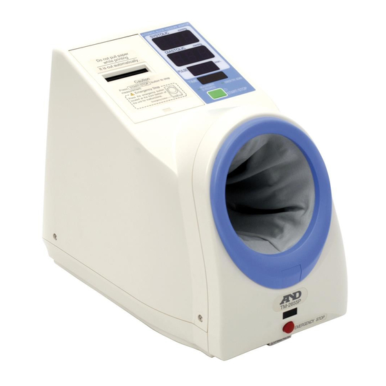
2-1 Main Unit Fig.2 TM-2655/TM-2655P whole view Note The printer unit is available only for the TM-2655P. The human sensor area appears the same for both models, but it functions only for the TM-2655P. The illustration above is not to scale. -
Page 13: Rear Panel
2-2 Rear Panel Fig.3 TM-2655/TM-2655P rear panel (The illustration above is not to scale.) 2-3 Symbols The symbols used with the TM-2655/TM-2655P have the following functions or meanings. Table 2 Symbol descriptions Symbols Function/Meaning Starts and stops a measurement. Turns the device on. -
Page 14: Installation
It is not exposed to direct sunlight. 2. Place the TM-2655/TM-2655P on a table solid enough to support its weight. 3. Adjust the height of the chair and table so that the arm insertion section is at the user’s heart level. Fig.4 Proper installation 4. -
Page 15: Operation
2. Take off your jacket. If you wear a thick jacket, take it off for a better measurement. Note Wearing a thick jacket may cause a faint pulse, and result in a measurement error. 3. Adjust the height of the chair and table. - Page 16 To stop the measurement at any time, press the START/STOP switch. The quick exhaust will reduce the pressure in the cuff and the cuff will become loose. If the air is not exhausted even when the START/STOP switch is pressed, press the EMERGENCY STOP switch.
-
Page 17: Setting The Clock
5. SETTING THE CLOCK 5-1 Clock Adjustment Mode The clock is set in the clock adjustment mode. The clock adjustment mode display and switches used are as shown below: Fig.10 Switches for setting the clock and the clock adjustment mode display... - Page 18 11. Press the SELECT switch to return to the measurement mode. Note If no operation is performed for one minute, while setting the minutes section and for five seconds while setting the others, the settings performed so far will be confirmed and the device will return to the measurement mode.
-
Page 19: Installing The Printer Paper
Confirm that the paper is fed straight. If not, re-install the paper because it may cause a paper jam. 5. Lower the lever and feed the paper. The paper will be cut automatically. 6. Close the cover. Press lightly on the center of the printer cover to secure it in position. -
Page 20: Setting The Functions
2. Press the COUNTER switch to select the function number to set. Each time the switch is pressed, the funciton number changes: from “f01” to “f02” to “f03”. 3 Press the switch to select the function parameter. 4. When the settings are complete, turn the power off and turn it on again. The settings are saved. -
Page 21: Description Of The Functions
Displays the results for 5 seconds. Displays the results for 10 seconds. Displays the results for 20 seconds. Ff05 Terminals 1 and 2 to a PC External connection Terminal 1 to a PC Terminal 2 to a card reader... -
Page 22: Printing Samples
Graph printing 3-line printing Table printing Bit pattern printing Fig.13 Printing samples Note Bit pattern printing is available only for the TM-2655P. With this format, some items such as the company name can be printed. For details, contact your nearest dealer. -
Page 23: Communication Specifications
8. COMMUNICATION SPECIFICATIONS The TM-2655/TM-2655P is equipped with two RS-232C channels. Various settings for each channel are available in the function setting mode. Refer to “7-2 Description of the Functions” for details. 8-1 Channel 1 : Miniature DIN 8-pin CAUTION The personal computer and medical equipment connected to the device are not allowed to be in the patient area. -
Page 24: Channel 2: D-Sub 9-Pin
8-2 Channel 2: D-sub 9-pin CAUTION The personal computer and medical equipment connected to the device are not allowed to be in the patient area. The personal computer used must conform to IEC60950 Specifications Table 7 Channel 2 specifications Standard... -
Page 25: Maintenance
Smooth the cover cloth near the grooves. 5. Replace the rear panel, the armrest, and the front frame in the reversed order of removal. Slide the cover upward to secure it in position. -
Page 26: Replacing The Fuses
3. Re-install the fuse holder caps. Fig.19 Fuse holders Note Use only fuses of the proper type, voltage and current rating as specified on the rear panel, and that conform to IEC60127. 9-3 Checking the Counter The TM-2655/TM-2655P is equipped with a counter function, which indicates how many times the device has measured blood pressure. -
Page 27: Maintenance
9-5 Maintenance Do not open the device. It uses delicate electronic components and an intricate air unit that could be damaged. If you can not fix the problem using the troubleshooting instructions, request service from your supplier or from the A&D service group. The A&D service group will provide technical information, spare parts and units to authorized suppliers. -
Page 28: Options And Consumables
9-7 Options and Consumables Options and consumables available for the TM-2655/TM-2655P are shown below. Order them from the nearest dealer. Use the part numbers when ordering. Table ················································ TM-9325 Standard stool·································· TM-9312 Chair (Gas shock suspension)········· TM-9315A Printer paper (5 rolls) ······················· AX-PP147-S Arm cuff cover ·····································AX-133003442-S... -
Page 29: Troubleshooting
10. TROUBLESHOOTING If the TM-2655/TM-2655P does not function properly or an error code appears, try the following corrective actions. Table 10 Troubleshooting Problem Check this Corrective action Is the power cable connected Nothing appears in Connect the power cable properly. -
Page 30: External Dimensions
11. EXTERNAL DIMENSIONS Fig.20 External dimensions Note The illustration above indicates the TM-2655P with the printer unit. The dimensions are the same for the TM-2655 and TM-2655P.
Need help?
Do you have a question about the tm-2655p and is the answer not in the manual?
Questions and answers