Maktec MT070/ Technical Information
Cordless hammer driver drill 14.4v/ 18v
Hide thumbs
Also See for MT070/:
- Instruction manual (41 pages) ,
- Instruction manual (40 pages) ,
- Instruction manual (52 pages)
Table of Contents
Advertisement
Quick Links
Download this manual
See also:
Instruction Manual
T
ECHNICAL INFORMATION
Model No.
Description
C
ONCEPT AND MAIN APPLICATIONS
These cordless products are the new maktec aesthetic design models,
and have been developed to use 1.1Ah Li-ion batteries (L1451/ L1851)
and charger (DC1851) newly designed to provide cost-competitive
advantage to maktec brand cordless tools.
The specification difference between these models are:
MT070/ 14.4V Cordless driver drill
MT071/ 18V Cordless driver drill
MT080/ 14.4V Cordless hammer driver drill
MT081/ 18V Cordless hammer driver drill
S
pecification
Specification
Voltage: V
Capacity: Ah
Battery
Cell
Charging time (approx.): min.
Chuck capacity: mm (")
No load speed: min-
Impacts per min.: min-
Capacity: mm (")
Torque setting
Clutch torque setting: N.m (in.lbs)
Max. fastening
torque: N.m (in.lbs)
Lock torque: N.m (in.lbs)
Electric brake
Mechanical speed control
Variable speed control
Reversing switch
Weight according to
EPTA-Procedure 01/2003: kg (lbs)
*1 with Battery L1451
*2 with Battery L1851
S
tandard equipment
Battery L1451 for MT070/ MT080
Battery L1851 for MT071/ MT081
Charger DC1851
Battery cover
Plastic carrying case
Note: The standard equipment for the tool
shown above may vary by country.
MT070/ MT071
MT080/ MT081
Cordless Driver Drill 14.4V/ 18V
Cordless Hammer Driver Drill 14.4V/ 18V
Model No.
MT070
10 (3/8)
=rpm
Low/ High
1
=ipm Low/ High
1
Steel
10 (3/8)
Wood
Masonry
Hard joint
30 (270)
Soft joint
14 (120)
21 (190)
1.4 (3.1)
Model No.
Length (L)
201 (7-7/8)
Width (W)
Height (H)
236 (9-1/4)
MT071
14.4
18
1.1
Li-ion
60 with DC1851
13 (1/2)
0 - 400/ 0 - 1,400
N/A
13 (1/2)
25 (1)
36 (1-7/16)
N/A
16 stage + drill mode
1.0 - 4.0 (9 - 35)
42 (370)
24 (210)
38 (340)
Yes
Yes (2 speed)
Yes
Yes
1.7 (3.7)
1.5 (3.2)
*1
*2
O
ptional accessories
Charger DC1851
Battery L1451 for MT070/ MT080
Battery L1851 for MT071/ MT081
Drill bits for wood
Drill bits for steel
Drill bits for masonry for MT080/ MT081
Driver bits
W
Dimensions: mm (")
MT070
MT071
MT080
223 (8-3/4)
216 (8-1/2)
82 (3-1/4)
239 (9-3/8)
236 (9-1/4)
MT080
MT081
14.4
18
10 (3/8)
13 (1/2)
0 - 6,000/ 0 - 21,000
10 (3/8)
13 (1/2)
25 (1)
36 (1-7/16)
10 (3/8)
13 (1/2)
30 (270)
42 (370)
14 (120)
24 (210)
21 (190)
38 (340)
1.7 (3.8)
*1
*2
PRODUCT
P 1/ 6
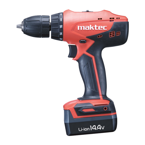
L
H
(model MT070)
MT081
238 (9-3/8)
82 (3-1/4)
239 (9-3/8)
Advertisement
Table of Contents

Subscribe to Our Youtube Channel
Related Manuals for Maktec MT070/


Summary of Contents for Maktec MT070/
- Page 1 Description Cordless Hammer Driver Drill 14.4V/ 18V ONCEPT AND MAIN APPLICATIONS These cordless products are the new maktec aesthetic design models, and have been developed to use 1.1Ah Li-ion batteries (L1451/ L1851) and charger (DC1851) newly designed to provide cost-competitive advantage to maktec brand cordless tools.
- Page 2 P 2/ 6 epair CAUTION: Repair the machine in accordance with “Instruction manual” or “Safety instructions”. [1] NECESSARY REPAIRING TOOLS Code No. Description Use for Hex wrench 8 removing / assembling Drill chuck Plastic hammer removing Drill chuck [2] DISASSEMBLY/ASSEMBLY [2]-1.
- Page 3 P 3/ 6 epair [3] DISASSEMBLY/ASSEMBLY [3]-2. DC motor DISASSEMBLING It is not necessary to remove Drill chuck from Gear assembly when replacing DC motor. (1) Remove nine 3x16 Tapping screws and Housing R from Housing L. (2) DC motor can be replaced as drawn in Fig. 5. Fig.
- Page 4 P 4/ 6 epair [3] DISASSEMBLY/ASSEMBLY [3]-3. Speed change lever assembly DISASSEMBLING Refer to Fig. 5. ASSEMBLING Do the reverse of the disassembling steps. Assemble Speed change lever to Gear assembly as drawn in Fig. 7. Fig. 7 2. Fit the projection of lever of Gear 3.
- Page 5 P 5/ 6 ircuit diagram Fig. D-1 Color index of lead wires' sheath Black Yellow DC Motor Flag receptacles Switch Line filters (Housing L side) (Housing L side) (Housing R side) Switch unit Part No. 638861-4: with Line filters and Flag receptacles Part No.
- Page 6 P 6/ 6 iring diagram Fig. D-2 Fig. D-3 Connect Flag receptacles so that the wire connecting Wire connecting portions portions face Housing L side. of Flag receptacles Housing L Red mark Connect Flag receptacles Terminal so that the wire connecting portions face +, - and AS marks on Terminal.
Need help?
Do you have a question about the MT070/ and is the answer not in the manual?
Questions and answers