Advertisement
Quick Links
Download this manual
See also:
Manual
DaVinci Fireplace
See Through Indoor / Outdoor
Framing and Window
Installation Instructions
These Instructions are an addendum to the
This addendum is only for use with the Indoor / Outdoor Window Kits, replacing
the framing dimensions section and providing addition installation instructions for
Qualified Installers Only:
This unit may only be installed by qualified installers.
We recommend that the sealed glass panel be installed by a qualified
glazier or specially trained 'Da' Vinci installer.
© Travis Industries
DaVinci Fireplace
Installation Manual
the "Extruded Aluminum Window Kit".
4/21/2016
17601913
Advertisement

Related Manuals for Travis Industries DaVinci

Summary of Contents for Travis Industries DaVinci
- Page 1 DaVinci Fireplace See Through Indoor / Outdoor Framing and Window Installation Instructions These Instructions are an addendum to the DaVinci Fireplace Installation Manual This addendum is only for use with the Indoor / Outdoor Window Kits, replacing the framing dimensions section and providing addition installation instructions for the “Extruded Aluminum Window Kit”.
- Page 2 Installation Order We strongly recommend having a qualified framer on hand while installing the exterior window onto a DaVinci custom fireplace. This process requires very precise measurements. A framer may be required to match the position of the fireplace to the external framing.
- Page 3 Indoor / Outdoor Unit Overview This manual details the framing and installation of the ‘Da’ Vinci Indoor / Outdoor See Through, fireplace models outline in table: Viewable area width Viewable area height Unit Weight Input (BTU’s) (including window) 36.00” 12.00”, 20.00”, 30.00”, 36.00” 380lbs 43,500 btu’s 48.00” 12.00”, 20.00”, 30.00”, 36.00” 480lbs 58,000 btu’s 60.00” 12.00”, 20.00”, 30.00”, 36.00” 580lbs 72,500 btu’s 72.00” 12.00”, 20.00”, 30.00”, 36.00” 680lbs 87,000 btu’s 84.00” 12.00”, 20.00”, 30.00”, 36.00” 780lbs 101,500 btu’s 96.00” 12.00”, 20.00”, 30.00”, 36.00” 880lbs 116,000 btu’s 108.00” 12.00”, 20.00”, 30.00”, 36.00” 980lbs 130,500 btu’s 120.00” 12.00”, 20.00”, 30.00”, 36.00” 1080lbs ...
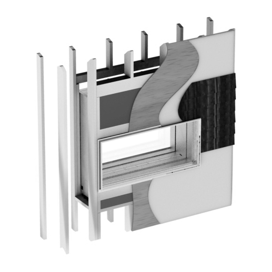
- Page 4 Indoor / Outdoor Unit Part 1: Aluminum Window Frame Installation Step 1 ‐ Framing Fireplace Placement Requirements: Fireplace must be installed on a level surface capable of supporting the fireplace and vent. Fireplace must be placed directly on wood or non‐combustible surface (not on linoleum or carpet). Fireplace should be located out of traffic and away from furniture and draperies. Fireplace may be placed in a bedroom. Clearances: (a) Clearance to Sides of Fireplace: 0”. (b) Clearance to Back of Fireplace: 0”. (c) Clearance to Front of Fireplace: 0”. NOTE: do not cover the glass opening with any material. NOTE: Side walls may be placed directly to the side of the fireplace. (d) Clearance to Bottom of Fireplace: 0” (may be placed directly on subfloor). Optional warm air blower: See additional clearance instructions included with warm air circulation kit if installed. Figure 2: Framing Dimensions. Example shows typical framing using 2” x 6” lumber for the outside wall and 2” x 4” lumber for the inner wall. See chart for framing dimensions based upon unit viewable area. Inner wall, 2” x 4”...
-
Page 5: Step 2 - Unit Placement
Indoor / Outdoor Unit Viewable A (width) B B B B C area width (Height=12”) (Height=20”) (Height=30”) (Height=36”) (depth) 36.00” 39.50” 46.75” 54.75” 64.75” 70.75” ” 48.00” 51.50” 46.75” 54.75” 64.75” 70.75” ” 60.00” 63.50” 46.75” 54.75” 64.75” 70.75”... - Page 6 Indoor / Outdoor Unit Step 3 – Attach 3/16” Butyl Seal The 3/16” butyl seal comes supplied on a roll. To attach the seal, start at the center bottom of the frame and attach, lining up the edge of the tape with the outside edge of the aluminum frame lip. Note: Make sure the butyl tape does not cover any of the mounting holes in the aluminum frame as this could cause damage to the seal by wrapping around the mounting screw during attachment. Caution: Butyl tape is sticky and will adhere on contact, take care to attach in the correct position before applying. Start attaching at center bottom ‐ Line edge of tape up with edge of frame Do not cover mounting holes Butyl seal attachment: Using denatured alcohol clean aluminum frame attachment area (avoid fingerprints). Start at bottom center of frame and applying light pressure, unroll the 1/16” butyl tape to form a continuous seal (do not remove backing paper at this point). Check and make sure all mounting holes are clear. ...
- Page 7 Indoor / Outdoor Unit Step 4 – Attaching the Aluminum Frame to the Unit Attaching the aluminum frame to unit using the supplied zinc coated, self‐taping #8 x 1” screws Attach the aluminum frame to the unit using the supplied self‐taping #8 screws. Remove the backing tape from 3/16” Butyl tape. Line up the inside edge of the frame with the inside edge of the unit (the opening size is the same for viewable unit area as the internal dimension of the aluminum frame). Care should be taken to carefully align the frame to the unit as the butyl tape will adhere upon contact. Clean unit surface. Check alignment of aluminum frame ...
- Page 8 Indoor / Outdoor Unit Step 5 – Attach 2” x 6” Front Cross Members Attach 2” x 6” cross members. Face of cross members should be flush to the side timber facing and tight against the unit face. Slot the cross members into the channel formed between the unit and the aluminum extrusion. Step 6 – Attach insulation, 3/8” outer sheathing & vapour barrier Attach 1 rigid foam 1/2” insulation (R value = 5.78R) into the cavities on the top and bottom face of the unit. ...
- Page 9 Indoor / Outdoor Unit Step 7 – Attach final finishing material Attach final finishing (example shows cedar siding). This slots into the front channel of the extrusion. Part 2: Sealed Glass Panel Installation Note: The glass panel may be installed into the aluminum frame at any time following completion of Step 4. It is understood that the required contractors may not be available to complete the outer wall finishing. For clarity the process of installing the sealed glass frame is shown with the frame in view only, it is assumed the frame has been attached to the unit ready to receive the sealed glass panel. Step 8 – Attach 3/16” Butyl Seal Line up the 3/16” butyl with the inside edge of the extrusion ...
- Page 10 Indoor / Outdoor Unit Step 9 – Attach Sealed Glass Lie the edge of the sealed glass panel on the rubber blocks. Note: Avoid contact with butyl seal as you may damage it by dragging the seal. Place in the rubber block rests for the sealed panel Aluminum extrusion 3/8” Butyl seal Glass panel Wedging tools Push the sealed panel against the butyl rubber seal. Use wedging tools to firmly locate the sealed panel in position. Step 10 – Attach Sealed Glass Panel Retainers Locate retainers with tab facing down and located into slot between glass and extrusion. 3 2 4 1 Place in the glass panel retainers. Note: For ease of installation they should be placed in the order shown © Travis Industries 4/21/2016 17601913 ...
- Page 11 Indoor / Outdoor Unit Step 11 – Attach Glass Panel Rubber Seal Lubricate seal with soap solution Seal located in position between glass panel and retainer The glass panel rubber retainer is placed pushed Add 1.00” to into the gap between the retainer and the glass required length panel. The Rubber seal should be cut to length allowing for shrinkage over time. It is recommended that the rubber be cut I.00” longer than the required. Install in the following order: Bottom. Top. ...
Need help?
Do you have a question about the DaVinci and is the answer not in the manual?
Questions and answers