Sign In
Upload
Manuals
Brands
Tecnam Manuals
Aircrafts
P2002 JF
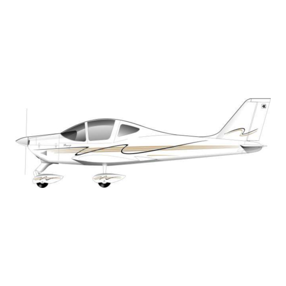
Tecnam P2002 JF Two-seat Light Aircraft Manuals
Manuals and User Guides for Tecnam P2002 JF Two-seat Light Aircraft. We have
1
Tecnam P2002 JF Two-seat Light Aircraft manual available for free PDF download: Maintenance Manual
Tecnam P2002 JF Maintenance Manual (1290 pages)
Brand:
Tecnam
| Category:
Aircrafts
| Size: 48 MB
Table of Contents
Chapter 0 1
13
Foreword
13
Manual Breakdown and Organization
14
Abbreviations
17
Occurrence Reporting Instructions
19
Conversion Charts
23
Table of Contents
27
Chapter 0 2
29
Conversion Factors
29
Conversion Tables
31
Liters-US Gallon Conversion Table
31
Inch Pound - Newton Meter Conversion Table
32
Foot Pound - Newton Meter Conversion Table
33
Airplane General Description
35
Airplane General Description
41
Chapter 0 3
41
General Views
41
Wing
42
Wing Structure
42
Fuselage
43
Empennages
44
Stabilator Structure
45
Aileron System
46
Flight Controls
46
Flight Control System (Flaps)
47
Engine and Propeller
48
Engine Mount and Propeller
48
Landing Gear
49
Main Landing Gear
49
Nose Landing Gear
49
Brake System
50
Brake System Layout (Standard)
50
Hydraulic Differential Brake Circuit (Optional)
51
Fuel System
52
Fuel System Layout
52
Electrical System
53
Electrical System (Typical Configuration)
53
Pitot and Static System
54
Pitot System Scheme
54
Heating/Defrost System
55
Ventilation, Cabin Heat and Windshield Defrost
55
General Features
56
Airworthiness Limitations
59
Time Limits and Maintenance Schedule
67
General
75
Component Time Limits
77
Time Limits Table
77
Component Time Limits
78
Inspection Program
79
Inspection Program Table
79
A List of Applicable Cmms Is Herein Reported
82
Engine Inspections
82
Propeller Inspections
82
Vendor Equipment Inspections
82
Scheduled Maintenance
83
Lubrication
97
Approved Lubricants
98
Lubrication Charts and Schedule
99
Inspection Points
101
Rudder Lower Bushing and Teflon Road-Stop
103
Rudder Upper Bushing
103
Stabilator Rod-End
104
Stabilator Supports
104
Aircraft Moving Surfaces Hinges
106
Flaps Lower Bushing
106
Stabilator Rod End
107
Stabilator Rod Loops
107
Aileron Rod Ends and Rotation Bushing
108
Aileron Rod Loop
108
Flap Rod Attachments (RH)
109
Flap Rod End
109
Flaps Rod Attachment (LH) and Flaps Actuator Attachments
110
Pedals and Rudder Cables Attachments
111
Steering Attachments
111
Brake Attachments (if Applicable)
112
Control Column
112
NLG Attachment and Steering Attachments
113
Shock Absorber Attachments
113
Brakes Pump Attachments (if Applicable)
114
Pedals Attachments (if Applicable)
114
Connection Pedal-Rudder
115
Steering Control Road
115
Main Gear Wing Bearings
116
Parking Brake Lever (if Applicable)
116
Nose Gear Wing Bearings
117
Corrosion Prevention
118
Operation in Highly Dusty or Industrial Pollution Environment
120
Special Scheduled Maintenance
120
Operation in High Salt or High Humidity Environments
121
Operation in Extreme Cold Environment
124
Operation on Soft or Unusual Terrain
124
Lightning Strike
126
Unscheduled Maintenance
126
Engine Over-Speed, Over-Temp, Loss of Oil or Sudden Stoppage
127
Severe Turbulence, Hard or Overweight Landing
127
Flood Damage, Immersion in Water
129
Dimensions and Inspection Caps
135
Dimensions and Areas
140
General Dimensions
140
Cabin Dimensions
142
Control Surfaces Travel Limits
142
Inspection Caps
144
Jacking
149
Jacking the Aircraft
155
Jacking – Maintenance Practices
155
Lifting Point
155
Removing Airplane from Jacks
157
Leveling and Weighing
159
Leveling
165
Longitudinal Leveling
166
Transversal Levelling
167
Weighing
168
CG and Moment Computation Chart
170
Towing and Taxiing
173
Maintenance Practices
179
Towing
179
Taxing
181
Parking, Mooring, Storage and Return to Service
183
Parking
189
Chapter 10
189
General
189
Procedure
189
Mooring
190
Mooring Scheme
191
General
192
Procedure
192
Storage and Return to Service
192
Restoration from Storage
193
Markings and Placards
195
Chapter 11
201
Markings and Placards
201
Exterior Colour
202
Airplane Typical Exterior Colouring
202
Maintenance Practices
202
Ornament Installation
203
Ornament Removal
203
Paint Features
203
External Placards
205
Maintenance Practices
205
Placard Installation
205
Placard Removal
205
Fuselage External Placards
206
Internal Placards
207
Self-Adhesive Placard Installation
207
Self-Adhesive Placard Removal
207
Stiff Riveted Placard Installation
208
Stiff Riveted Placard Removal
208
Instrument Panel (Analogic System)
209
Servicing
215
General
221
Servicing
221
Fuel System – Servicing Practices
222
General
222
Drain Valve (RH Shown, LH Opp.) and Filler Caps
223
Fuel Contamination Check Procedure
224
Fuel System Drainage Procedure
224
Refueling Procedure
224
General
225
Oil System - Servicing Practice
225
Oil Level Checking and Filling Procedure
226
Oil Tank Max and Min Marking
226
Oil Tank Location
227
Oil Change Procedure
228
Oil Tank Drain Valve
228
Oil Tank Cleaning
229
COOLANT SYSTEM - Servicing Practices
230
Coolant System Level Check
230
Coolant Expansion Tank
231
Coolant Overflow Bottle
231
General
232
SEATS - Handling and Cleaning Instructions
232
Seats Removal and Installation Procedure
233
Polycarbonate Components Cleaning
234
Polyurethane Components Cleaning
234
Seats Cleaning Instructions
234
Leather Dress Cover Cleaning
235
Procedure and Tools
235
Airplane Cleaning Instructions
236
General
236
Engine Cleaning Procedure
237
External Surfaces Cleaning Procedure
237
Windows Cleaning Procedure
237
Battery - Servicing Practices
238
General
238
Installation Procedure
238
Removal Procedure
238
General
240
Wheels - Servicing Practices
240
Brake Oil Level Check Procedure
241
Brake System - Servicing Practices
241
General
241
Lever Toe System
241
General
242
TOE BRAKE SYSTEM (Optional)
242
Oil Brake System Tank
243
Oil Level Check Procedure
243
Standard Practices Airframe
247
Torque Data
252
Chapter 20
252
Maintenance Practices
252
General
252
Torque Values
254
AN Threads
254
ISO Metric Threads
254
Cables Tension
255
Maintenance Practices
255
Cable Damage
256
Control Cables
256
Inspection Technique
256
Maintenance Practices
256
Control Cable Inspection Technique
257
External Wear Patterns
258
Internal Cable Wear
258
Cable Fittings
259
Pulley Wear Patterns
260
General
261
Safetying - Maintenance Practices
261
Installation of Safety Wiring
262
Safety Wiring: Securing Screws, Nuts, Bolts, and Snap Rings
262
Safety Wiring Twisting by Hand
263
Securing Caps, Drain Cocks, Valves
265
Safety-Wiring Procedures
266
Alternate Method for Securing with Cotter Pins
269
Securing with Cotter Pins
269
Turnebuckles
270
Safetying Turnbuckles: Acceptable Methods
272
Double-Wrap Method
273
Single-Wrap Method
274
Heating and Ventilation
277
Cabin Heating
282
Hot Air System
282
Chapter 21
282
Description and Operation
282
Cabin Heat/Defrost Command Knobedition
284
Carb. Heat Command Lever
284
Cabin Heat Valve
285
Hot Air Valve
285
Cold Air Access to Carburettors
286
ATA 21-10 Troubleshooting
288
Troubleshooting
288
Maintenance Practices
289
Cabin Heat and Defrost Valves Control Cable Rigging
290
Cabin Heating and Defrost System Operational Test
290
Hot Air Valves Replacement
291
Hot Air Knob in off Position
292
Hot Air Knob in on Position
292
Hot Air Valve in Close Position
292
Hot Air Valve in Open Position
292
Hot Air Valves Control Cable Replacement
293
Hot Air Knob Assy
294
Hot Air Knob Housing
294
Hot Air Valve/Command Cable Fitting
294
Description and Operation
296
Ventilation
296
Ventilation System
296
Diffuser in Open Position
297
Naca Intake Access Point
297
Pushing Point
297
Troubleshooting
298
Maintenance Practices
299
Communications
301
Comm 1 and 2
306
Garmin GNS 430W
306
GNS 430W Front Panel
306
Chapter 23
306
Description and Operation
306
Garmin GNS 530W
307
GNS 530W Front Panel
307
Garmin GMA 340
308
Garmin Apollo SL30/SL40
309
SL30 Front Panel
309
SL40 Front Panel
309
Speaker Location
309
Control Description SL 30
310
The COMM Radio Features
310
The NAV Radio Features
310
Control Description SL 40
311
Antennas
312
SL 40 Radio COMM Features
312
Antennas: ADF – Marker Beacon – Transponder
314
ATA 23-10 GMA 340 Troubleshooting
315
ATA 23.10 GNS 430W / 530W Troubleshooting
315
ATA 23-10 SL30/SL40 Troubleshooting
316
Maintenance Practices
317
GNS 430W / 530W Unit Removal/Installation
318
GNS 430W / 530W Periodic Maintenance
319
GMA 340 Unit Removal/Installation
320
GMA 340 Periodic Maintenance
321
SL30 / SL40 Unit Removal/Installation
322
SL30 / SL 40 Periodic Maintenance
323
COMM Antenna Removal/Installation
324
Chapter 24
332
General
332
Power Generation
334
Generators
334
Generator Features
334
Battery
335
Generator Failure Light
335
External Power Source
336
Voltmeter and Ammeter
336
ATA 24-10 Troubleshooting
338
Maintenance Practices
340
Maintenance Practices: General Rules
341
Battery Removal and Installation
342
Battery Servicing
342
Generator Removal and Installation
342
Battery Capacity Test
346
Volt-Meter/Ammeter Replacement
347
Description and Operation
350
Power Distribution
350
Avionic BUS
351
Battery Bus
351
Troubleshooting
352
Maintenance Practices
353
Master Switch Relays Replacement
354
Master Switch / External Power Relay
355
Starter Relay Replacement
356
Starter Relay
357
Generator Regulator Replacement
358
Generator Regulator
359
Equipment and Furnishing
361
Chapter 25
366
Equipment and Interiors - General
366
Cabin Interiors
366
Cabin Interiors
367
Description and Operation
367
Maintenance Practices
369
Cabin Panels Removal/Installation
370
Description and Operation
378
Safety Belts
378
Safety Belt Upper Attachment
379
Maintenance Practices
380
Safety Belt Removal Procedure
380
Safety Belt Inspection Procedure
381
Safety Belt Clealing Procedure
382
Emergency Locator Transmitter (Elt)
383
Antenna ELT
384
ELT Location
384
Elt Installation Procedure
385
Elt Removal Procedure
385
Maintenance Practices
385
First Aid Kit
387
Fire Protection
389
Fire Extinguisher
396
Fire Extinguisher Check
396
Flight Controls - General
405
Chapter 27 Description and Operation
405
Ailerons
407
Description and Operation
407
Aileron Control System
408
Maintenance Practices
411
First Bellcrank Replacement
412
Connecting Rod Replacement
413
Control Rod
413
Bellcrank Fixing Screw
414
Control Axis Removal/Installation
414
Control Axis Fixing Bolt
415
Floor Panel
415
Control Column Removal/Installation
416
Control Column Item (A) Upper Link
417
Control Column / Control Axis Exploded View
418
Aileron Command Cable Item (C)
419
Control Column Item (B) Lower Link
419
Control Column / Cabin Truss Attachments Item (E)
420
Stabilator Control Rod Item (D)
420
Description and Operation
422
Flap Control
422
Flaps
422
Ata 27.30 Troubleshooting
425
Maintenance Practices
426
Flap Actuator Replacement
427
Flap Actuator
428
Flap Position Transmitter Replacement
429
Flap Position Transmitter
430
Description and Operation
432
Stabilator and Trim
432
Stabilator Command Exploded View
433
Trim Tab Command
434
Maintenance Practices
435
Stabilator Setting
435
Stabilator Trim Tab Control Cable Replacement
435
Stabilator Setting
436
Stabilator Trim Tab Actuator Replacement
437
Tail Cone Fairing
438
Trim Actuator Assy
438
Cotter Pin
439
Trim Tab Actuator
439
Actuator Fixing Bolts
440
Stabilator Trim Tab Adjustment
441
Description and Operation
442
Rudder
442
Rudder and Steering Control System
443
Maintenance Practices
444
Rudder Control Cable Replacement
445
Rudder Cables/Pedals Attachments
446
Redder Cables Attachments (LH Shown RH Opposite)
447
Rudder Cables Pulleys
447
Rudder Control Cable Joints
448
Fuel System
457
Chapter 28
457
Description and Operation
457
Fuel System Layout Arrangement
458
Standard Mesh Filter
459
Fuel Tank Vent Hose
460
Tank Vent Connection
460
Fuel Tank Vent (Inner View)
461
ATA 28 Fuel System Troubleshooting
462
Fuel Quantity Indication Test
463
Maintenance Practices
463
Fuel Quantity Indicator Test
464
Electric Fuel Pump Test
465
Fuel Pressure Indicator
466
Fuel Pump Light
466
Fuel Quantity Sender Replacement
467
Fuel Qty. Sender
468
Fuel Sender Inspection Cap
468
Electric Fuel Pump Replacement
469
Electrical Fuel Pump Support
470
Fuel Pump Splice Location
470
Fuel Quantity Indicator Replacement
471
Fuel Pressure Indicator Replacement
472
Fuel Vent Inspection
473
Gascolator Cleaning
473
Fuel Tank Inspection and Cleaning
474
Electric Fuel Pump Filter Cleaning
475
Gascolator
475
Gascolator (Exploded View)
476
Fuel Tank Assy
476
Electrical Fuel Pump
478
Ice Protection
481
Indicating System
487
Instrument Panel (Typical Layout)
492
Instrument Panel Left Side (Typical Layout)
493
Instrument Panel Right Side (Typical Layout)
494
Instrumental Panel Central Panel (Typical Layout)
495
Annunciator Panel
496
Screwed Indicators Replacement
498
Examples of Screwed Indicators
498
Examples of Screwed Indicators (Rear View)
498
Clamped Indicators Replacement
500
Annunciator Panel Lights Replacement
502
Unscrewing Attaching Screws
503
Airplane MLG and NLG
513
Chapter 32
513
Landing Gear
513
Mlg and Brakes
514
Description and Operation
514
ATA 32-10 Troubleshooting
515
Maintenance Practices
517
MLG Removal
518
MLG Installation
519
Mlg/Fuselage Bolts Torque Values
520
Brake Fluid Line Removal
521
Cover
521
Nuts Removal/Installation
522
Fit Brake Flexible
523
Fit Brake Flexible Line
523
On-Aircraft Main Wheels Inspection
525
Main Wheel Removal
527
Main Wheel Scheme
528
Main Wheel Installation
529
Brake System (P/N 30-9)
530
Cover Installation/Removal
530
Bolt Installation/Removal
531
MLG Wheel
531
Bolt Removal/Installation
532
Main Wheel Disassembly
533
Main Wheel Reassembly
534
Main Wheel Tyre Removal
535
Main Wheel Tyre Installation
536
Brake Assembly Removal
538
Brake Assembly Installation
539
Brake Lining Replacement
541
Brake Assembly (P/N 30-9)
542
Torque Plate
543
Torque Plate Installation/Removal
543
Description and Operation
545
Lever Brake System
545
Toe Brake System
546
Rudder Pedals and Brake Master Cylinders (Pilot and Co-Pilot Side)
547
Toe Brake System Scheme
548
ATA 32-20 Troubleshooting
549
Maintenance Practices
552
Brake Fluid Draining
553
Brake Fluid Replacing
553
Brake Pads Replacing
554
Description and Operation
555
Nose Landing Gear
555
Maintenance Practices
557
Installation of Nose Gear Fairings
558
Removal of Nose Gear Fairing
558
On-Aircraft Nose Wheel Inspection
559
Removal of Nose Wheel
559
NLG Wheel Scheme
560
Nose Wheel Disassembly
560
Nose Landing Gear
561
Nose Wheel Reassembly
561
Nlg Damper On-Aircraft Maintenance
562
Nose Landing Gear Dumper
563
Lights
566
Internal Lights
571
Vfr Night Internal Additional Equipment
571
Couple of Instruments Lights
571
Chapter 33
571
Description and Operation
571
Dome Light
572
Torch
572
Torch Location
573
ATA 33-10 Troubleshooting
574
Maintenance Practices
575
Led Light Replacement
576
Maintenance Practices: General Rules
576
Annunciator Panel Lights Replacement
577
Description and Operation
578
External Lights
578
Landing Lights
579
Strobe Lights
579
Strobe Lights Mode Switch
580
Vfr External Additional Configuration
580
VFR Night Landing Light
580
Troubleshooting
582
Maintenance Practices
583
Taxi and Landing Light Replacement
584
Wingtip Nav and Strobe Lights Assy Replacement
584
Strobe Lights Control Unit Replacement
585
Navigation
588
CHAPTER 34 Pitot-Static System
593
Alternate Static Port
595
Stall Warning System
595
Troubleshooting
596
Maintenance Practices
597
Instruments Replacement
598
Pitot-Static System – Leak Test
599
Pitot Leak Test
600
Static Leak Test
601
Pitot Static System - Drainage
602
Pitot-Static System - Cleaning
603
Attitude and Heading
606
Heading and Attitude Instruments
606
Maintenance Practices
607
Magnetic Compass Replacement
608
Foreword
609
Magnetic Compass
609
Attitude Indicator Replacement
611
Directional Gyro Replacement
613
Description and Operation
615
Position Determining
615
Primary Navigation Receiver (Optional)
615
Garmin GI 106A VOR/LOC/GS Indicator
616
GI 106A Displays Following Information
616
Alternative Navigation Receiver
617
MD200-306 Indicator
617
Gps
618
GTX 328 Transponder
619
GTX 330 Transponder
619
Transponder
619
NAV Equipment Antennas
620
ATA 34-30 GNS 430W/530W Troubleshooting
621
ATA 34-30 SL30 Troubleshooting
622
ATA 34-30 GTX 328/330 Troubleshooting
623
Maintenance Practices
624
Gns 430W/530W Unit Removal/Installation
625
Battery Replacement
626
Gns 430W Periodic Maintenance
626
Cleaning the Front Panel
627
Display Backlight
627
Gns 530W Periodic Maintenance
627
Sl30 Unit Removal/Installation
628
Cleaning the Font Panel
630
Sl30 Periodic Maintenance
630
Gps Antenna Removal/Installation
632
Transponder Removal/Installation
634
Transponder Periodic Maintenance
635
Transponder Antenna Removal/Installation
636
Vhf-Nav Antenna Replacement
638
Standard Practices - Structures
641
Structure Classification
652
Damage Classification and Repairs
654
Structure Examination
654
Damage Evaluation
658
Primary Structural Components
658
Secondary and Tertiary Structural Components
658
Windshield and Canopy Repair
660
Consumable Materials
664
Alignment Check
671
Canopy
674
Canopy and Windshield Structure
679
Canopy – General
679
Windshield and Canopy
680
Chapter 52
681
Maintenance Practices
681
Canopy Handle Support Installation
682
Canopy Handle and Screw
682
Canopy Handle Support
683
Canopy Repair
684
Door Safety Lock - General
685
Lateral Safety Lock
686
Upper Safety Lock (External)
686
Upper Safety Lock (Internal)
687
Emergency Lock Repair
688
Maintenance Practices
688
Safety Lock Replacement
689
Canopy Removal / Installation - General
690
Canopy Typical Layout
690
Maintenance Practices
692
Canopy Removal/Installation Procedure
693
Emergency Locks Removal
694
Locking Pin
694
Canopy Key Lock
695
Screws Removal
695
Canopy Lifting Direction
696
Bearing Track Removal/Installation Procedure
698
Allen Screws and Bolts
699
Travel Stop
699
Bearings
700
Cabin Truss
707
Description and Operation
707
Fuselage
707
Tail Cone
708
Fuselage Longitudinal Stations
709
Maintenance Practices
710
Tail Fairing Replacement
711
Trim Tab Screws
711
Rear Side of Stabilator
712
Stabilator Pin
712
Tail Fairing and Torque Tube
713
Stabilator and Rudder
716
Description and Operation
721
Stabilator
721
Stabilator Control
722
Torque Tube and Trim Control
723
Maintenance Practices
726
Stabilator Removal /Installation
727
Trim Tab Removal/Installation
729
Stabilator Torque Tube Assy
730
Stabilator Balance Mass Check
731
Description and Operation
732
Fin and Rudder
732
Rudder and Steering Control
733
Maintenance Practices
734
Rudder Removal/Installation
735
Cable Tension Check
737
Windows
739
Windows
744
Chapter 56
744
Description and Operation
744
Maintenance Practices
748
Windshield Replacement
749
Side Windows Replacement
752
Canopy Windows Replacement
754
Canopy Window
755
Wings
758
Wing Stations
765
Wing Removal
768
Aileron
770
Wing-Fuselage Pins
770
Wing Installation
771
Flaps Removal
773
Wing-Flap Attachments and Mass Balance
773
Flaps Installation
774
Aileron Removal
775
Wing-Aileron Attachments
775
Aileron Installation
776
RH Aileron
777
Wing Inspection
778
Wing Lower Surface
779
Wing Upper Surface
779
Propeller
782
Propeller
788
Chapter 61
788
Description and Operation
788
Troubleshooting
790
Maintenance Practices
791
Propeller Removal
792
Hub-Propeller Screws
793
Ogive
793
Propeller Installation
794
Power Plant
798
Chapter 54
803
Engine Cowlings
803
Description and Operation
803
Maintenance Practices
806
Engine Cowling Removal
807
Lower Engine Mount Pins and Screws
808
Engine Cowling Inspection Cap
809
Engine Cowling Installation
809
Description and Operation
810
Engine Assy
810
Engine Mount
810
Shock Mount Attachments
811
Maintenance Practices
812
Engine Mount Removal
813
Engine Mount Installation
814
Pre-Installation Procedure
814
Engine Mount Attachment Points
815
Air Intakes
817
Carburetor Heating System
817
Description and Operation
817
Maintenance Practices
819
Air Filter Cleaning and Replacement
820
Air Filter
821
Air Inlet
821
Description and Operation
822
Engine Drainage
822
Maintenance Practices
824
Drainage Hoses Replacement
825
Liquid Cooling System
828
Scheme of Liquid Cooling System
833
Standard Configuration
833
Optional Configuration
834
Scheme of Liquid Cooling System with Thermostatic Valve
834
CHT Indicator
835
ATA 75-10 Troubleshooting
839
Thermostatic Valve Replacement
841
Thermostatic Valve Serflexes
841
Radiator Replacement
842
Radiator Hoses
843
Radiator-Engine Mounting Bolts
843
Exhaust
846
Exhaust
851
Chapter 78
851
Description and Operation
851
Muffler and Heat Exchanger
852
Maintenance Practices
853
Exhaust Removal
854
Exhaust Installation
855
Exhaust Spring
856
Detail
857
Heat Exchanger
857
Air System Hoses
859
Heat Exchanger Inspection
860
Heat Exchanger Removed
861
Muffler with Heat Exchanger
861
Oil System
864
Oil System
869
Chapter 79 Description and Operation
869
Rotax 912S Oil Circuit Schematic (Oil Temperature below 90°C)
870
Rotax 912S Oil Circuit Schematic (Oil Temperature 90°C to 100°C)
871
Rotax 912S Filter Cartridge (Section)
872
Rotax 912S Oil Circuit Schematic (Oil Temperature > 100°C)
872
Oil Radiator
873
Radiator
873
Oil Tank
874
Oil Tank Ventilation Flow
874
Maintenance Practices
877
Oil Tank Cleaning
878
Oil Tank Replacement
878
Oil Cooler Replacement
880
Oil System Schematic
882
Thermostatic Valve
883
Radiators Assembly
884
Oil Pressure Sensor Replacement
885
Oil Pressure Indicator Connector
886
Oil Pressure Sensor
886
Starting
888
Starting System
893
Chapter 80
893
Description and Operation
893
ATA 80-10 Troubleshooting
895
Maintenance Practices
896
Starter Relay Replacement
897
Tecnam P2002JF AMM Supplements List
900
Introduction
910
Supplement S4
910
Maintenance Practices
922
Stabilator Installation
923
Stabilator Pre-Installation Procedure
923
Maintenance Practices
914
Seats Installation
915
Seats Removal
915
Chapter 12 - Servicing
912
Chapter 55 - Stabilator and Rudder
920
Chapter 57 - Wings
928
Control Cable and Hoses Pre-Installation Procedure
930
Wing Installation
930
Wing Pre-Installation Procedure
930
Chapter 72 - Engine
944
Maintenance Practices
944
Engine Check
944
Powerplant Controls Rigging
944
Tecnam P2002 JF AMM Supplement S1
954
Tecnam P2002 JF AMM Supplement S2
989
Tecnam P2002 JF AMM Supplement SG-3
1025
Abbreviations
1037
Introduction
1037
Chapter O4 - AIRWORTHINESS LIMITATIONS
1040
Chapter 5 - TIME LIMITS and MAINTENANCE SCHEDULE
1041
Chapter 31 - INDICATING SYSTEM
1067
Troubleshooting
1067
GDU 620 PFD/MFD Removal/Installation
1079
GRS 77 AHRS Removal/Installation
1079
GMU 44 Removal/Installation
1079
GDC 74A (ADC) Removal/Installation
1079
Software Upload
1084
Maintenance Practices
1101
Standby Attitude Indicator Replacement and Testing
1101
Chapter 92 - WIRING DIAGRAMS
1110
Tecnam P2002-JF AMM Supplement S2
1140
Maintenance Practices
1152
Seats Installation
1153
Seats Removal
1153
Chapter 55 - Stabilator and Rudder
1158
Maintenance Practices
1160
Stabilator Pre-Installation Procedure
1160
Control Cable and Hoses Pre-Installation Procedure
1168
Wing Installation
1168
Wing Pre-Installation Procedure
1168
Engine Check
1182
Maintenance Practices
1182
Powerplant Controls Rigging
1182
Tecnam 2002-JF AMM Supplement S-1
1192
Advertisement
Advertisement
Related Products
Tecnam P2002-JF
Tecnam P2002 Sierra
Tecnam P2008 JC
Tecnam P2006T
Tecnam P2008 TC
Tecnam P2008
Tecnam P2010 2015
Tecnam P2010tdi
Tecnam P2012
Tecnam P96 Golf/100
Tecnam Categories
Aircrafts
Autopilot System
More Tecnam Manuals
Login
Sign In
OR
Sign in with Facebook
Sign in with Google
Upload manual
Upload from disk
Upload from URL