Table of Contents
Advertisement
Available languages
Available languages
Quick Links
BEDIENUNGSANLEITUNG
USER MANUAL
MODE D'EMPLOI
MANUAL DEL USUARIO
CF-200
Lighting effect
©
Für weiteren Gebrauch aufbewahren!
Copyright
Keep this manual for future needs!
Nachdruck verboten!
Gardez ce mode d'emploi pour des
Reproduction prohibited!
utilisations ultérieures!
Réproduction interdit!
Guarde este manual para posteriores usos.
Prohibida toda reproducción.
Advertisement
Table of Contents

Related Manuals for Future light CF-200 Lighting effect


Summary of Contents for Future light CF-200 Lighting effect
-
Page 1: User Manual
BEDIENUNGSANLEITUNG USER MANUAL MODE D'EMPLOI MANUAL DEL USUARIO CF-200 Lighting effect © Für weiteren Gebrauch aufbewahren! Copyright Keep this manual for future needs! Nachdruck verboten! Gardez ce mode d’emploi pour des Reproduction prohibited! utilisations ultérieures! Réproduction interdit! Guarde este manual para posteriores usos. Prohibida toda reproducción. -
Page 2: Table Of Contents
MULTI-LANGUAGE-INSTRUCTIONS Inhaltsverzeichnis Table of contents Sommaire Contenido EINFÜHRUNG..............................4 SICHERHEITSHINWEISE..........................4 BESTIMMUNGSGEMÄßE VERWENDUNG..................... 5 GERÄTEBESCHREIBUNG ..........................6 Features ................................. 6 Geräteübersicht.............................. 7 INSTALLATION ..............................8 Lampeninstallation/Lampenwechsel ......................8 Lampenjustierung............................9 Überkopfmontage............................9 Master/Slave-Betrieb............................ 11 Blackout-Buchse ............................11 Anschluss an den DMX-512 Controller / Verbindung Projektor - Projektor ..........11 Anschluss ans Netz............................ - Page 3 INTRODUCTION ............................. 29 INSTRUCTIONS DE SÉCURITÉ ........................29 EMPLOI SELON LES PRESCRIPTIONS ....................... 30 DESCRIPTION DE L'APPAREIL........................31 Features ............................... 31 Aperçue des parties ............................. 32 INSTALLATION .............................. 33 Installer/Remplacer la lampe ........................33 Ajustage de la lampe............................ 34 Montage par dessus de la tête........................34 Opération Master/Slave ..........................
-
Page 4: Einführung
BEDIENUNGSANLEITUNG CF-200 Lichteffekt Lesen Sie vor der ersten Inbetriebnahme zur eigenen Sicherheit diese Bedienungsanleitung sorgfältig durch! Alle Personen, die mit der Aufstellung, Inbetriebnahme, Bedienung, Wartung und Instandhaltung dieses Gerätes zu tun haben, müssen - entsprechend qualifiziert sein - diese Bedienungsanleitung genau beachten - die Bedienungsanleitung als Teil des Produkts betrachten - die Bedienungsanleitung während der Lebensdauer des Produkts behalten - die Bedienungsanleitung an jeden nachfolgenden Besitzer oder Benutzer des Produkts weitergeben... -
Page 5: Bestimmungsgemäße Verwendung
Unbedingt lesen: Bei Schäden, die durch Nichtbeachtung der Anleitung verursacht werden, erlischt der Garantiean- spruch. Für daraus resultierende Folgeschäden übernimmt der Hersteller keine Haftung. Das Gerät darf nicht in Betrieb genommen werden, nachdem es von einem kalten in einen warmen Raum gebracht wurde. -
Page 6: Gerätebeschreibung
- - -m Das Bildzeichen bezeichnet den Mindestabstand zu beleuchteten Gegenständen. Der Abstand zwischen Lichtaustritt und der zu beleuchteten Fläche darf 0,5 Meter nicht unterschreiten! Das Gerät darf nur über den Montagebügel installiert werden. Um eine gute Luftzirkulation zu gewährleisten, muss um das Gerät ein Freiraum von mindestens 50 cm eingehalten werden. -
Page 7: Geräteübersicht
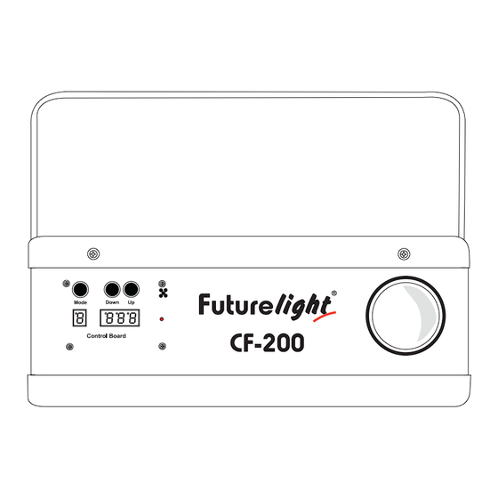
Geräteübersicht Future light Mode Down CF-200 Control Board (1) Hängebügel (2) Control Board (3) Gehäuse (4) Gehäuseschrauben (5) Objektivlinse/Fokus (6) Fangsicherung (7) Lampensystem (8) Feststellschraube (9) Sicherungshalter (10) Netzanschluss (11) DMX-Ausgangsbuchse (12) DMX-Eingangsbuchse (13) Blackout-Buchse 7/54 51837540X18NXS_V_1_1.DOC... -
Page 8: Installation
(14) Mode-Taste Down (15) Down-Taste Mode (16) Up-Taste (17) Display (18) Mikrofon (19) Kontroll-LED Control Board INSTALLATION Lampeninstallation/Lampenwechsel LEBENSGEFAHR! Lampe nur bei ausgeschaltetem Gerät einsetzen! Netzstecker ziehen! Zur Installation benötigen Sie eine MSD/HSD 200 GY-9,5, MSD/HSD 250 GY-9,5 oder MSD 250/2 GY-9,5 Lampe. -
Page 9: Lampenjustierung
Vorgehensweise: Schritt 1: Lösen Sie die Befestigungsschrauben X und Y des Lampensystems und entnehmen Sie dieses vorsichtig aus dem Gehäuse. Schritt 2: Wird eine defekte Lampe ausgetauscht, entfernen Sie zunächst die defekte Lampe aus dem Lampenhalter. Schritt 3: Setzen Sie die Lampe vorsichtig in den Lampenhalter ein. Schritt 4: Führen Sie das Lampensystem wieder in das Gehäuse ein und ziehen Sie die Befestigungss- schrauben fest. - Page 10 Der Unternehmer hat dafür zu sorgen, dass sicherheitstechnische und maschinentechnische Einrichtungen vor der ersten Inbetriebnahme und nach wesentlichen Änderungen vor der Wiederinbetriebnahme durch Sachverständige geprüft werden. Der Unternehmer hat dafür zu sorgen, dass sicherheitstechnische und maschinentechnische Einrichtungen mindestens alle vier Jahre durch einen Sachverständigen im Umfang der Abnahmeprüfung geprüft werden. Der Unternehmer hat dafür zu sorgen, dass sicherheitstechnische und maschinentechnische Einrichtungen mindestens einmal jährlich durch einen Sachkundigen geprüft werden.
-
Page 11: Master/Slave-Betrieb
Master/Slave-Betrieb Im Master/Slave-Betrieb lassen sich zwei Geräte synchronisieren, die dann von einem Mastergerät gesteuert werden. An der Rückseite des CF-200 befindet sich eine XLR-Einbaubuchse (DMX Out) und ein XLR-Einbaustecker (DMX In), über die sich mehrere Geräte miteinander verbinden lassen. Wählen Sie das Gerät aus, das zur Steuerung der Effekte dienen soll. Dieses Gerät arbeitet dann als Master-Gerät und steuert das Slave-Gerät, das über eine symmetrische Mikrofonleitung mit dem Master- Gerät verbunden wird. -
Page 12: Anschluss Ans Netz
Die Verbindung zwischen Controller und Projektor sowie zwischen den einzelnen Geräten muss mit einem zweipoligen geschirmten Kabel erfolgen. Die Steckverbindung geht über 3-polige XLR-Stecker und -Kupplungen. Belegung der XLR-Verbindung: Wenn Sie Controller mit dieser XLR-Belegung verwenden, können Sie den DMX-Ausgang des Controllers direkt mit dem DMX-Eingang des ersten Gerätes der DMX-Kette verbinden. -
Page 13: Dmx-Gesteuerter Betrieb
Wenn Sie z. B. einen Fußschalter an die Blackout-Buchse angeschlossen haben, können Sie den Licht- austritt des Projektors manuell verriegeln (Blackout-Modus) und wieder einschalten. Master/Slave-Betrieb Verbinden Sie die Master/Slave-Geräte und nehmen Sie die Einstellungen wie oben beschrieben vor. DMX-gesteuerter Betrieb Über Ihren DMX-Controller können Sie die einzelnen Geräte individuell ansteuern. -
Page 14: Reinigung Und Wartung
DMX-Wert Eigenschaft 0-10 Weiß 11-21 Magenta 22-32 Gelb 33-43 Dunkelblau 44-54 Hellgrün 55-65 Pink 66-76 Tiefblau 77-87 Dunkelorange 88-98 Hellgelb 99-109 Hellblau 110-120 Hellorange 121-127 Dunkelgrün 128-191 Rainboweffekt vorwärts mit abnehmender Geschwindigkeit 192-255 Rainboweffekt rückwärts mit abnehmender Geschwindigkeit Steuerkanal 4 – Gobos, Reset, Strobe DMX-Wert Eigenschaft Geschlossen... -
Page 15: Sicherungswechsel
4) Die elektrischen Anschlussleitungen dürfen keinerlei Beschädigungen, Materialalterung (z.B. poröse Leitungen) oder Ablagerungen aufweisen. Weitere, auf den jeweiligen Einsatzort und die Nutzung abgestimmte Vorschriften werden vom sachkundigen Installateur beachtet und Sicherheitsmängel behoben. LEBENSGEFAHR! Vor Wartungsarbeiten unbedingt allpolig vom Netz trennen! Das Gerät sollte regelmäßig von Verunreinigungen wie Staub usw. -
Page 16: Technische Daten
TECHNISCHE DATEN Spannungsversorgung: 230 V AC, 50 Hz Gesamtanschlusswert: 440 W DMX-Steuerkanäle: DMX 512-Anschluss: 3-pol. XLR Musiksteuerung: über eingebautes Mikrofon Blitzrate: 9 Hz Anzahl der Farben: 11 dichroitische + weiß Anzahl der Gobos: 14 statische Gobos + offen Maße (LxBxH): 260 x 380 x 150 mm Gewicht: 11 kg... -
Page 17: Introduction
USER MANUAL CF-200 Lighting effect CAUTION! Keep this device away from rain and moisture! Unplug mains lead before opening the housing! For your own safety, please read this user manual carefully before you initial start-up. Every person involved with the installation, operation and maintenance of this device has to - be qualilfied - follow the instructions of this manual - consider this manual to be part of the total product... -
Page 18: Operating Determinations
If the device has been exposed to drastic temperature fluctuation (e.g. after transportation), do not switch it on immediately. The arising condensation water might damage your device. Leave the device switched off until it has reached room temperature. This device falls under protection-class I. The power plug must only be plugged into a protection class I outlet. -
Page 19: Description Of The Device
Always fix the fixture with an appropriate safety-rope. The maximum ambient temperature t = 45° C must never be exceeded. Operate the device only after having become familiar with its functions. Do not permit operation by persons not qualified for operating the device. Most damages are the result of unprofessional operation! Please use the original packaging if the device is to be transported. -
Page 20: Overview
Overview Future light Mode Down CF-200 Control Board (1) Mounting bracket (2) Control Board (3) Housing cover (4) Housing screws (5) Objective-lens/Focus (6) Safety eyelet (7) Lamp system (8) Fixation screw (9) Fuseholder (10) Power supply (11) DMX-Out socket (12) DMX-In socket... -
Page 21: Installation
(14) Mode-button (15) Down-button Down Mode (16) Up-button (17) Display (18) Microphone (19) Control LED Control Board INSTALLATION Installing/Replacing the lamp DANGER TO LIFE! Only install the lamp with the device switched off! Unplug from mains before! For the installation, you need one MSD/HSD 200 GY-9.5, MSD/HSD 250 GY-9.5 or MSD 250/2 GY-9.5 lamp. -
Page 22: Lamp Adjustment
Step 3: Insert the lamp into the lamp holder. Step 4: Replace the lamp system in the housing and tighten the fixation screws. Step 5: Adjust the lamp as described under lamp adjustment. Do not operate this device with opened cover! Lamp adjustment The lampholder is aligned at the factory. -
Page 23: Master/Slave-Operation
IMPORTANT! OVERHEAD RIGGING REQUIRES EXTENSIVE EXPERIENCE, including (but not limited to) calculating working load limits, installation material being used, and periodic safety inspection of all installation material and the device. If you lack these qualifications, do not attempt the installation yourself, but instead use a professional structural rigger. -
Page 24: Blackout-Socket
Blackout-socket If you wish to lock the light output - e.g. via an optional footswitch (Blackout-mode), connect your footswitch via a mono-jack plug to the Blackout-socket. Occupation mono 1/4“ jack-plug: Sleeve In Phase (+) Ground DMX-512 connection / connection between fixtures The wires must not come into contact with each other, otherwise the fixtures will not work at all, or will not work properly. -
Page 25: Connection With The Mains
Ω Caution: At the last fixture, the DMX-cable has to be terminated with a terminator. Solder a 120 resistor between Signal (–) and Signal (+) into a 3-pin XLR-plug and plug it in the DMX-output of the last fixture. Connection with the mains Connect the device to the mains with the enclosed power supply cable. -
Page 26: Dmx-Protocol
Note: After switching on, the CF-200 will automatically detect whether DMX 512 data is received or not. If the data is received, the control LED flashes. If there is no data received at the DMX-input, the control LED lights up permanently. -
Page 27: Cleaning And Maintenance
104-111 Gobo 12 112-119 Gobo 13 120-127 Gobo 14 128-132 Closed 133-137 Reset (after 3-5 seconds) 138-159 Forwards gobo-change with increasing speed 160-200 Strobe effect with increasing speed 201-250 Random strobe effect with increasing speed 251-255 Open CLEANING AND MAINTENANCE The operator has to make sure that safety-relating and machine-technical installations are inspected by an expert after every four years in the course of an acceptance test. -
Page 28: Replacing The Fuse
Replacing the fuse If the fine-wire fuse of the device fuses, only replace the fuse by a fuse of same type and rating. Before replacing the fuse, unplug mains lead. Procedure: Step 1: Open the fuseholder on the rearpanel with a fitting screwdriver. Step 2: Remove the old fuse from the fuseholder. -
Page 29: Introduction
MODE D'EMPLOI CF-200 Effet lumineux ATTENTION! Protéger de l'humidité. Débrancher avant d’ouvrier le boîtier! Pour votre propre sécurité, veuillez lire ce mode d'emploi avec attention avant la première mise en service. Toute personne ayant à faire avec le montage. la mise en marche. le maniement et l’entretien de cet appareil doit - être suffisamment qualifiée - suivre strictement les instructions de service suivantes. -
Page 30: Emploi Selon Les Prescriptions
Attention: Tout dommage occasionné par la non observation des instructions de montage ou d'utilisation n'est pas couvert par la garantie. L'appareil ne devrait pas être mis en service lorsqu'il à été transporté d'un endroit froid à un endroit chaud. Il se forme de la condensation qui pourrait endommager l'appareil. -
Page 31: Description De L'appareil
Cet appareil a seulement été conçu pour un installation grâce à la lyre de montage. Afin d'assurer une ventilation optimale, il est nécéssaire de laisser un espace d'au moins 50 cm autour de l'appareil. L'appareil ne doit jamais toucher des objets ou surfaces dans l'ambiance. Lors de l'installation du projecteur, au démontage du projecteur et pendant l'exécution des travaux de service faites attention à... -
Page 32: Aperçue Des Parties
Aperçue des parties Future light Mode Down CF-200 Control Board (1) Lyre de fixation (2) Unité de contrôle (3) Boîtier (4) Vis de boîtier (5) Objectif/Foyer (6) Oeillet de sécurité (7) Système de lampe (8) Vis de la lyre (9) Porte-fusible... -
Page 33: Installation
(14) Touche Mode Down Mode (15) Touche Down (16) Touche Up (17) Affichage (18) Microphone (19) DEL de contrôle Control Board INSTALLATION Installer/Remplacer la lampe DANGER DE MORT! Toujours mettre hors tension avant de mettre en place l'ampoule! Débrancher avant toute manipulation! Pour l'installation, vous avez besoin d'une lampe MSD/HSD 200 GY-9,5, MSD/HSD 250 GY-9,5 ou MSD 250/2 GY-9,5. -
Page 34: Ajustage De La Lampe
Ne jamais mettre l’appareil sous tension avant que le boîtier ne soit refermé. Ajustage de la lampe Le porte-lampe de l’appareil est ajusté à l‘usine. Comme les lampes à utiliser diffèrent d’un fabricant à l’autre, il pourrait devenir nécessaire de procéder à un nouveau ajustage de la position du porte-lampe. -
Page 35: Opération Master/Slave
Procédure: Dans le cas idéal, l'appareil devrait être installé en dehors du secteur de présence de personnes. IMPORTANT! LE MONTAGE PAR DESSUS DE LA TETE EXIGE UN HAUT NIVEAU D‘EXPERIENCE. Ceci comprend (mais n’est pas limitée seulement) des calculations pour la définition de la capacité de charge, le matériel d’installation utilisé... -
Page 36: Douille Blackout
Control Board: Master-mode: DMX-mode Slow Slave-mode: Slave 1 Master-mode: Master-mode: Sound-control Standby Choississez le mode Master désiré pour l'appareil master. Choississez le mode Slave pour l'appareil slave. Douille Blackout Si vous voulez verrouiller la sortie de lumière, par ex. par un interrupteur sur pieds (mode Blackout), s'il vous plaît connectez votre interrupteur sur pieds à... -
Page 37: Alimentation
Occupation de la connection XLR: Quand vous utilitsez un contrôleur avec cette occupation, vous pouvez directement connecter la sortie DMX du contrôleur avec l'entrée DMX du premier appareil de la chaîne DMX. Quand vous voulez connecter des contrôleurs DMX avec des sorties DMX différentes, il est nécéssaire d'utiliser des câbles d'adaptation. Connecter une chaîne DMX serielle: Connectez la sortie DMX du premièr appareil de la chaîne avec l'entrée DMX de l'appareil prochaine. -
Page 38: Contrôle Par Dmx
Opération Master/Slave Connectez les appareils master et slave et entrez l'ajustage comme décrit ci-dessus. Contrôle par DMX Vous pouvez contrôler les projecteurs individuels grâce à votre contrôleurs DMX. Chaque canal DMX a une ocupation différente avec des caractéristiques différentes. Pour choisir les caractéristiques différentes, il faut que vous ouvriez la sortie de lumière (canal de contrôle 4, valeur DMX 251-255). -
Page 39: Nettoyage Et Maintenance
Valeur DMX Caractéristique 0-10 Blanc 11-21 Magenta 22-32 Jaune 33-43 Bleu enfoncé 44-54 Vert claire 55-65 Pink 66-76 Bleu 77-87 Orange enfoncé 88-98 Jaune claire 99-109 Bleu claire 110-120 Orange claire 121-127 Vert enfoncé 128-191 Effet "Rainbow" avant à vitesse croissante 192-255 Effet "Rainbow"... -
Page 40: Remplacer Le Fusible
4) Les lignes de raccord électriques ne doivent pas avoir aucun endommagement, viellissement de matériel (par ex. des lignes poreux) ou des dépôts. D’autres régulations adaptées au lieu d’utilisation respectif et à l’utilisation, seront respectées par l’installateur compétent et des défauts de sécurité seront éliminés. -
Page 41: Caractéristiques Techniques
CARACTÉRISTIQUES TECHNIQUES Alimentation: 230 V AC, 50 Hz Puissance de rendement: 440 W Canaux de contrôle DMX: Connexion DMX-512: XLR 3-pôles Fréquence des flash: 9 Hz Nombre de couleurs: 11 dichroïques + blanc Nombre de gobos: 14 gobos statiques et ouvert Dimensions (LxlxH): 260 x 380 x 150 mm Poids:... -
Page 42: Introducción
MANUAL DEL USUARIO CF-200 Efecto luminoso ¡PRECAUCIÓN! ¡Evite el contacto de este aparato con la lluvia y la humedad! ¡ Desconectar de la corriente antes de abrir la caja! POR SU PROPIA SEGURIDAD, POR FAVOR LEA ESTE MANUAL DEL USUARIO DETENIDAMENTE ANTES DE LA CONEXIÓN INICIAL! Toda persona implicada en la instalación, manejo y mantenimiento de este aparato tiene que -estar cualificada... -
Page 43: Instrucciones De Manejo
Si el aparato ha estado expuesto a grandes cambios de temperatura (p.e. tras el transporte), no lo enchufe inmediatamente. La condensación de agua producida podría dañar su aparato. Deje el aparato desconec- tado hasta que llegue a la temperatura ambiente. Este aparato pertenece a la clase de protección I. -
Page 44: Descripción Del Aparato
= 45° C nunca debe ser excedido. La máxima temperatura ambiente t Maneje el aparato sólo después de familiarizarse con sus funciones. No permita el manejo a personas que no conocen el aparato lo suficientemente bien. La mayoría de los daños son causados por manejo inadecuado de inexpertos. -
Page 45: Descripción De Las Partes
Descripción de las partes (1) Lyra de montaje (2) Unidad de control (3) Caja (4) Tornillos de caja (5) Objetivo/Foco (6) Ojete de seguridad (7) Sistema de lámpara (8) Tornillo de fijación (9) Portafusible (10) Conexión a la red (11) Salida DMX (12) Entrada DMX (13) Casquillo Blackout 45/54... -
Page 46: Instalación
Down (14) Tecla Mode Mode (15) Tecla Down (16) Tecla Up (17) Pantalla (18) Micrófono Control Board (19) LED de control INSTALACIÓN Instalar/Reemplazar la lámpara ¡PELIGRO DE MUERTE! ¡Instale la lámpara únicamente con el aparato desenchufado! ¡Desenchufe-lo de la corriente! Para la instalación, Vd. -
Page 47: Montaje Por Encima De La Cabeza
Procedimiento: Paso 1: Desatornille los tornillos de fijación X, Y del sistema de lámpara y quitelo. Paso 2: Cuando quire reemplazar una lámpara defectuosa, primero quite la lámpara defectuosa del casquillo. Paso 3: Coloque la lámpara en el sistema de portalámparas. Paso 4: Vuelva a colocar el sistema de lámpara y atornille los tornillos de fijación. -
Page 48: Operación Master/Slave
El empresario debe asegurar que instalaciones de seguridad y de máquinas son inspeccionados por un perito en la extension de una inspección inicial cada cuatro años por lo menos. El empresario debe asegurar que instalaciones de seguridad y de máquinas son inspeccionados por un baquiano una vez por año. -
Page 49: Casquillo Blackout
Control Board: Master-mode: DMX-mode Slow Slave-mode: Slave 1 Master-mode: Master-mode: Sound-control Standby Seleccione el modo Master deseado para el aparato "Master". Seleccione el modo Slave respectivo para el aparato "Slave". Casquillo Blackout Cuando quiere cerrar la salida de luz (modo Blackout) - por ejemplo mediante un interruptor de pie opcional - conecte su interruptor de pie mediante un clavija jack mono con el casquillo Blackout. -
Page 50: Alimentación
La ocupación de la conexión XLR es: Cuando Vd. utilice los controladores con la ocupación descrita, puede conectar la salida DMX del controlador directamente con la entrada DMX del primer aparato de la cadena DMX. Cuando Vd. quiere conectar controladores DMX con otros salidas DMX, se tiene que utilizar cables de adaptación. Instalación de una cadena DMX: Conecte la salida DMX del primero aparato de la cadena con la entrada DMX del próximo aparato. -
Page 51: Control Por Dmx
Operación Master/Slave Conecte los aparatos master y slave y efectue los ajustes como descrito arriba. Control por DMX Vd. puede controlar los proyectores individuales mediante su controlador DMX. Cada canal DMX tiene otra ocupación con caracteristicas diferentes. Para llamar las caracteristicas diferentes, tiene que abrir la salida de luz (canal de control 4, valor DMX 251-255). -
Page 52: Limpieza Y Mantenimiento
110-120 Naranja claro 121-127 Verde obscuro 128-191 Efecto arco iris hacia adelante con velocidad creciente 192-255 Efecto arco iris hacia atras con velocidad creciente Canal de control 4 – Gobos, Reset, Strobe Valor DMX Caracteristica Cerrado 8-15 Abierto 16-23 Gobo 1 24-31 Gobo 2 32-39... -
Page 53: Reemplazar El Fusible
¡PRECAUCION! ¡La lente debe ser reemplazada cuando esté aparentemente deteriorada en caso de que su funcionamiento se vea afectado, por ejemplo a causa de fisuras o rasguños! La lente del objetivo requiere una limpieza semanal ya que el líquido de humo tiende a acumular residuos reduciendo la emisión de luz muy rápidamente. -
Page 54: Especificaciones Técnicas
ESPECIFICACIONES TÉCNICAS Alimentación: 230 V/50 Hz Consumo: 440 W Canales DMX: Conexión DMX 512: XLR tripolar Control por sonido: mediante micrófono incorporado Frecuencia de flash: 9 Hz Rueda de colores: 11 filtros de color dicróico más blanco Rueda de gobos: 14 gobos estáticos más abierto Dimensiones (La.xAn.xAl.): 260 x 380 x 150 mm...
Need help?
Do you have a question about the CF-200 Lighting effect and is the answer not in the manual?
Questions and answers