Table of Contents
Advertisement
Available languages
Available languages
Quick Links
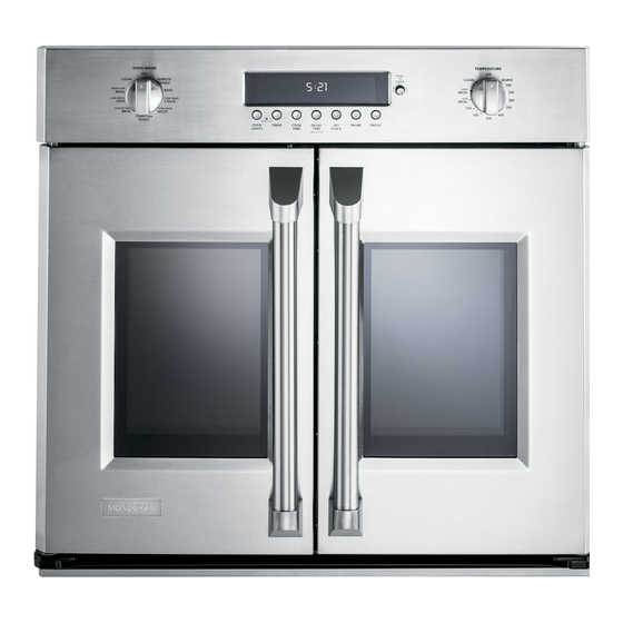
Installation Instructions
30" French Door Built-in Wall Ovens
Questions?
Call 1.800.GE.CARES (1.800.432.2737) or visit www.GEAppliances.com
In Canada, call 1.800.561.3344 or visit www.GEAppliances.ca
BEFORE YOU BEGIN
Read these instructions completely and
carefully.
•
Save these instructions
for local inspector's use.
•
Observe all governing
codes and ordinances.
• Note to Installer – Be sure to leave these
instructions with Consumer.
ATTENTION INSTALLER:
All electric wall ovens must be hard-wired (direct-wired) into an
approved junction box. A plug and receptacle is NOT permitted on these products.
FOR YOUR SAFETY:
WARNING:
Before beginning the installation, switch power off at the service panel and
lock the service disconnecting means to prevent power from being switched on accidentally. When the
service disconnecting means cannot be locked, securely fasten a prominent warning device, such as a tag,
to the service panel.
Be sure the oven is securely installed in a cabinet that is firmly attached to the house structure.
Weight on the oven door could cause the oven to tip and result in injury. Never allow anyone to climb, sit,
stand or hang on the oven door.
Make sure the wall coverings, counters and cabinets around the oven can withstand the heat
(up to 200°F [93.3°C]) generated by the oven.
MATERIALS YOU MAY NEED
Junction Box
Wire Nuts
Strain Relief Clamp for 1/2" Conduit
1
REMOVE PACKAGING MATERIALS
Failure to remove packaging materials could result in damage to the appliance. Remove all packing
parts from oven, racks and heating elements. Remove protective film and labels on the outer door
and control panel. Also, remove plastic on trims and panel, all tape around the oven and any shipping
screws securing the oven to the base pad. Open oven door and remove literature pack and oven
racks. Remove the bottom trim from the top of the oven. It will be installed at the end of the installation
process. The trim is wrapped separately and taped to the top of the unit.
• Note to Consumer – Keep these instructions
for future reference.
• Skill level – Installation of this appliance
requires a qualified installer or electrician.
• Proper installation is the responsibility
of the installer.
• Product failure due to improper installation
is not covered under Warranty.
• Product is for indoor use only.
TOOLS YOU MAY NEED
1/8" Drill Bit and Electric or Hand Drill
Phillips Screwdriver
Wire Strippers
9/16" Socket Wrench
1/8" Hex Key
DESIGN INFORMATION
FRENCH DOOR SINGLE OVEN INSTALLATIONS
The French Door single oven may be installed in a cabinet alone or above a warming drawer and/or below a
Microwave/Advantium. However, the French Door single oven is not allowed under a countertop or cooktop,
and it is not allowed to be installed flush to the front surface of the cabinet.
IMPORTANT: Always refer to individual installation instructions packed with each product for specific
requirements.
2
PREPARE THE OPENING
NOTE: If the cabinet does not have a solid bottom, two
braces or runners must be installed to support the weight
of the oven. For French Door ovens, the runners and
braces must support 220 lbs (98.8 kg).
NOTE: If marks, blemishes or the cutout opening are
visible above the installed oven, it may be necessary to
add wood shims under the runners and front trim until
the marks or opening are covered.
NOTE: If the cabinet does not have a front frame and
the sides are less than ¾" (1.9 cm) thick, shim both sides
equally to establish the cutout width.
2" x 4" (5 cm x 10 cm)
or Equivalent Runners Level
with Bottom of Cutout
and Flush with Sides of Cutout
C
L
Advertisement
Table of Contents

Related Manuals for Monogram ZET1FHSS


Summary of Contents for Monogram ZET1FHSS
-
Page 1: Installation Instructions
Installation Instructions DESIGN INFORMATION 30” French Door Built-in Wall Ovens FRENCH DOOR SINGLE OVEN INSTALLATIONS The French Door single oven may be installed in a cabinet alone or above a warming drawer and/or below a Microwave/Advantium. However, the French Door single oven is not allowed under a countertop or cooktop, and it is not allowed to be installed flush to the front surface of the cabinet. - Page 2 CUTOUT FOR SINGLE OVENS IN WALL CABINET CUTOUT FOR INSTALLATION OVER A WARMING DRAWER NOTE: If the cabinet does not have a front frame and the sides are less than ¾” (1.9 cm) thick, shim NOTE: Install the oven only with specific models listed on the label located on top of the oven. both sides equally to establish the cutout width.
-
Page 3: Electrical Requirements
CUTOUT FOR FRENCH DOOR UNDER A ELECTRICAL REQUIREMENTS MICROWAVE/ADVANTIUM AND OVER A WARMING DRAWER WARNING: This appliance must be properly grounded. NOTE: Install the oven only with specific models listed on the label located on top of the oven. WARNING: NOTE: Additional clearances between cutouts may be required. -
Page 4: Make Electrical Connections
ELECTRICAL REQUIREMENTS (CONT.) MAKE ELECTRICAL CONNECTIONS WARNING: This appliance must be supplied with the proper voltage and frequency and connected to an individual, properly grounded branch circuit, protected by a circuit breaker or fuse. See the rating plate located on the Switch power off at the service panel and lock the service disconnecting oven frame to determine the rating of the product. -
Page 5: Three-Conductor Branch Circuit Connection
THREE-CONDUCTOR BRANCH CIRCUIT CONNECTION SLIDE OVEN INTO OPENING NOTE: If residence leads are aluminum conductors, see WARNING • Lift oven into cabinet cutout using the in Section 3, Electrical Requirements. oven opening as a grip. Carefully push against oven front frame. Do not push When connecting to a three-conductor branch circuit, if local codes against outside edges. -
Page 6: Mount The Oven
MOUNT THE OVEN BOTTOM TRIM INSTALLATION • Slide oven out by 2” and attach the bottom trim through its mounting holes in front vertical brace WARNING: using two trim screws provided. Bottom trim lip must be placed under flange of bottom air duct. Mounting screws must be used. - Page 7 OVEN RACK GUIDE INSTALLATION DOOR ADJUSTMENT MECHANISM A. Locate included oven rack guide mounting hardware. Door Adjustment Mechanism is located on both the right and left doors at the bottom hinges. Only the left side Adjustment Mechanism is shown in this manual. B.
-
Page 8: Final Installation Checklist
FINAL INSTALLATION CHECKLIST • Check to make sure the circuit breaker is closed (RESET) or the circuit fuses are replaced. • Be sure power is in service to the building. • Check that all packing material and tape have been removed. Failure to remove these materials could result in damage to the appliance once the appliance has been turned on and surfaces have heated. -
Page 9: Antes De Comenzar
Instrucciones de instalación INFORMACIÓN DE DISE Hornos de pared Empotrables con Puertas Francesas de 30” INSTALACIONES DE HORNO SIMPLE CON PUERTA FRANCESA El horno simple con Puerta Francesa puede ser instalado en un gabinete aparte o sobre un cajón para ¿Preguntas? calentar y/o debajo de un Microondas/ Advantium. - Page 10 ABERTURA PARA HORNOS ÚNICOS EN UN GABIENTE DE PARED ABERTURA PARA INSTALACIÓN SOBRE UN CAJÓN CALENTADOR NOTA: Si el gabinete no cuenta con un armazón frontal y los lados son menores a un grosor de 3/4” (1,9 cm), coloque cuñas uniformemente sobre ambos lados para establecer al ancho de la abertura. NOTA: Instale el horno sólo con los modelos específicos listados en la etiqueta ubicada en la parte superior del horno.
-
Page 11: Requisitos Eléctricos
REQUISITOS ELÉCTRICOS ENCASTRE PARA PUERTA FRANCESA BAJO UN MICROONDAS/ ADVANTIUM Y SOBRE UN CAJÓN PARA CALENTAR ADVERTENCIA: Este aparato debe contar con una adecuada conexión a tierra. A. Coloque un riel con pedestal en cada rodadura del gabinete o centrado en el lado opuesto de la ADVERTENCIA: parte inferior del gabinete sólido nivelado con el lateral de la abertura del gabinete. -
Page 12: Realice Las Conexiones Eléctricas
REQUISITOS ELÉCTRICOS (CONT.) REALICE LAS CONEXIONES ELÉCTRICAS ADVERTENCIA: Este aparato debe recibir el voltaje y frecuencia adecuados, y debe conectarse a un circuito derivado individual con adecuada conexión a tierra, protegido por un interruptor de circuitos o fusible. Ver la placa de Desconecte la energía del panel de servicio y bloquee los medios clasificación ubicada en el armazón del horno para determinar la clasificación del producto. - Page 13 CONEXIÓN DE CIRCUITO DERIVADO DE TRES CONDUCTORES DESLICE EL HORNO DENTRO DE LA ABERTURA NOTA: Si los cables domésticos son conductores de aluminio, • Levante el horno dentro ver la ADVERTENCIA de la sección 3, Requisitos eléctricos. de la abertura del gabinete utilizando el horno abierto como agarre.
-
Page 14: Instale El Horno
INSTALE EL HORNO INSTALACIÓN DEL REBORDE INFERIOR • Una vez instalado el horno, adjunte el borde inferior a través de sus agujeros de montaje frente al ADVERTENCIA: soporte vertical, utilizando los dos tornillos con cabeza recortada provistos. El labio de la cubierta Deben utilizarse tornillos de montaje. - Page 15 GUÍA DE INSTALACIÓN DE LA ESTANTERÍA DEL HORNO (SI MECANISMO DE AJUSTE DE LA PUERTA CORRESPONDE) El Mecanismo de Ajuste de la Puerta se encuentra ubicado tanto en la puerta derecha como en la izquierda, en las bisagras inferiores. Sólo el lado izquierdo del Mecanismo de Ajuste es mostrado en este manual. A.
- Page 16 LISTA DE CONTROL FINAL DE LA INSTALACIÓN • Verifique que el interruptor de circuitos se encuentre cerrado (RESET) o que los fusibles del circuito se hayan reemplazado. • Asegúrese de que haya suministro eléctrico en el edificio. • Controle que se haya quitado todo el material de empaque y la cinta adhesiva. No quitar estos materiales puede provocar daños al electrodoméstico una vez que el aparato se haya encendido y las superficies se hayan calentado.
Need help?
Do you have a question about the ZET1FHSS and is the answer not in the manual?
Questions and answers