Table of Contents
Advertisement
INSTALLATION INSTRUCTIONS
These instructions must be affixed on or adjacent to the boiler
PL PL PL PL PL YMOUTH
YMOUTH
YMOUTH
YMOUTH
YMOUTH
W W W W W A A A A A TER
SERIES 2
Gas-Fir
Gas-Fir
Gas-Fir ed
Gas-Fir
Gas-Fir
Hot-W
Hot-W a a a a a ter
Hot-W
Hot-W
Hot-W
Boiler
Boiler s s s s s
Boiler
Boiler
Boiler
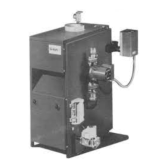
These Gas-Fired Water Boilers are low pressure, sectional
cast iron boilers Designed Certified by C.S.A. (Canadian
Standards Association) for use with Natural and Propane
Gases. They are constructed and hydrostatically tested for a
maximum working pressure of 50 psi (pounds per square
inch) in accordance with A.S.M.E. (American Society of
Mechanical Engineers) Boiler and Pressure Vessel Code
Section IV Standards for cast iron heating boilers.
Warning:
Improper installation, adjustment, alteration, service or maintenance can cause injury or
property damage. Refer to this manual. For assistance or additional information consult a qualified
installer, service agency or the gas supplier
DUNKIRK, NEW YORK 14084 • AREA CODE 716 366-5500
TER
TER
TER
TER
ed
ed
ed
ed
ter
ter
ter
ter
DUNKIRK BOILERS
MEMBER: The Hydronics Institute
MODEL PVWB
Continuous Pilot
1
MODEL PWB
Electronic
Intermittent Ignition
Advertisement
Table of Contents

Related Manuals for Dunkirk PVWB


Summary of Contents for Dunkirk PVWB
-
Page 1: Installation Instructions
Improper installation, adjustment, alteration, service or maintenance can cause injury or property damage. Refer to this manual. For assistance or additional information consult a qualified installer, service agency or the gas supplier DUNKIRK BOILERS DUNKIRK, NEW YORK 14084 • AREA CODE 716 366-5500 MEMBER: The Hydronics Institute... -
Page 2: Boiler Ratings And Capacities
AGA/CGA HEATING NET I=B=R (Inches) With With SECTIONS INPUT CAPACITY RATING FLUE "A" Vent Damper Vent Damper *MBH *MBH *MBH DIAMETER WIDTH PWB-2D PVWB-2D 37.5 4‡ PWB-3D PVWB-3D 11¼ PWB-4D PVWB-4D 14½ PWB-5D PVWB-5D 17¾ PWB-6D PVWB-6D PWB-7D PVWB-7D 24¼... -
Page 3: Before You Start
Before You Start If this boiler is installed in a building under construction, Gas Code (NFPA54/ANSI Z223.1-latest edition), or the manufacturer for correct orifice sizing information. High special care must be taken to insure a clean combustion air supply during the construction process. Airborne altitude orifices are available from the boiler manufacturer. -
Page 4: Locating The Boiler
Locating the Boiler 1. Select level location as centralized with piping system, and 6. Advise owner to keep air passages free of obstructions. as near chimney, as possible. Ventilating and combustion air must enter boiler room without restrictions. 2. Place crated boiler at selected location, remove crate by pulling crate sides from top and bottom boards. -
Page 5: Fresh Air For Combustion
Fresh Air for Combustion Provision for combustion and ventilation air must be in accordance with Section 5.3, Air for Combustion and Ventilation, of the National Fuel Gas Code, ANSI Z223.1-latest revision, or applicable provisions of the local building codes. NOTE WARNING If you use a fireplace or a kitchen or bathroom exhaust fan, Be sure to provide enough fresh air for combustion. -
Page 6: Installation - System Piping
Installation - System Piping 1. Place boiler in the selected location (as near chimney as The minimum design return water temperature to the boiler to possible.) Your boiler is shipped assembled. You need only prevent condensation in the boiler and venting is 120° F. The to install the Relief Valve and a drain line to carry any water minimum high limit setting is 140°... -
Page 7: Chimney And Vent Pipe Connection
Chimney and Vent Pipe Connection For boilers for connection to gas vents or chimneys, vent installations shall be in accordance with Part 7, Venting of Equipment, of the National Fuel Gas Code, ANSI Z223.1-latest revision and applicable provisions of the local building codes. CHECK YOUR CHIMNEY 7. -
Page 8: Vent Damper Operation
3. Insofar as is practical, close all building doors and windows FIG. 8 TYPICAL MASONRY CHIMNEY REQUIREMENTS and all doors between the space in which the appliances remaining connected to the common venting system are located and other spaces of the building. Turn on clothes dryers and any appliance not connected to the common venting system. - Page 9 located on the damper controller. The thermostat will control TYPICAL INSTALLATION FOR VENT DAMPER the burner firing as before, while the damper will remain open. NOT CAUTION AND FOOTNOTES DO NOT turn damper open manually or motor damage will 1. Install the vent damper to service only the single result.
-
Page 10: Check Gas Supply
Gas Supply Piping CHECK GAS SUPPLY FIG. 12 - GAS PIPE SIZES The gas pipe to your boiler must be the correct size for the length of the run and for the total Btu per hour input of all gas NATURAL GAS utilization equipment connected to it. -
Page 11: Electric Power Supply
Electrical Wiring All electrical work must conform to local codes as well as the a vertically mounted outlet box. It should be sensing average National Electrical Code, ANSI/NFPA-70, latest revision. In room temperature, so avoid the following: Canada, electrical wiring shall comply with the Canadian Elec- DEAD SPOTS: trical Codes, CSA-C22.1 and.2. - Page 12 WIRING DIAGRAMS FOR HOT WATER BOILERS INTERMITTENT IGNITION IF ANY OF THE ORIGINAL WIRE AS SUPPLIED WITH THIS APPLIANCE MUST BE REPLACED, IT MUST BE REPLACED WITH TYPE 105°C THERMOPLASTIC WIRE OR ITS EQUIVALENT. NOTE: THE CIRCULATOR HARNESS IS FACTORY WIRED TO THE AQUASTAT. THIS HARNESS NEEDS TO BE CONNECTED TO THE CIRCULATOR IN THE FIELD.
-
Page 13: Standing Pilot
WIRING DIAGRAMS FOR HOT WATER BOILERS STANDING PILOT IF ANY OF THE ORIGINAL WIRE AS SUPPLIED WITH THIS APPLIANCE MUST BE REPLACED, IT MUST BE REPLACED WITH TYPE 105°C THERMOPLASTIC WIRE OR ITS EQUIVALENT. NOTE: THE CIRCULATOR HARNESS IS FACTORY WIRED TO THE AQUASTAT. THIS HARNESS NEEDS TO BE CONNECTED TO THE CIRCULATOR IN THE FIELD. - Page 14 Equipment and Optional Accessories - What They Do RELIEF VALVE AIR ELIMINATING FITTING (AIR PURGER) You must have a relief valve on your boiler. Water expands as An air purger is used to remove excess air from the system. It it is heated.
-
Page 15: Starting Your Boiler
ROLLOUT SWITCH SPILL SWITCH (FLAME ROLLOUT SAFETY SHUTOFF) (BLOCKED VENT SAFETY SHUTOFF) The rollout switch is a temperature-sensitive fuse link device. The spill switch is a manual reset disc thermostat with a fixed setpoint It is located on the boiler base just outside the fire box. In the (340°... -
Page 16: For Your Safety Read Before Operating
For Your Safety Read Before Operating WARNING: If you do not follow these instructions exactly, a fire or explosion may result causing property damage, personal injury or loss of life. • Immediately call your gas supplier from a neighbor’s phone. A. -
Page 17: Operating Your Boiler
Continuous Pilot Boiler - VR8200A/VR8300A Gas Valve Operating Instructions Rotate the gas control knob counterclockwise 1. STOP! Read the safety information on page 16. to “PILOT” Push down and hold the red reset button while 2. Set the thermostat to lowest setting. you light pilot burner with a match. -
Page 18: Checking And Adjusting
FIG. 15 -VR8200A/VR8300A AUTOMATIC FIG. 14 - LIGHTING PILOT GAS VALVE FIG. 16 -VR8204A/VR8304M AUTOMATIC GAS VALVE FIG. 17 Checking and Adjusting ADJUST PILOT BURNER idea how the system works. Example: If your system does not give quite enough heat in very cold weather, you can raise the Pilot flame should surround 3/8"... -
Page 19: Maintaining Your Boiler
Maintaining Your Boiler recommend that you have the flue passages, burner BURNERS adjustment, and operation of the controls checked once each A visual check of the pilot end main burner flames should be year by a competent Service Technician. made at least once each year, preferably at the beginning of Before the start of each season (or whenever system has the heating season. -
Page 20: Service Hints
Service Hints You may avoid inconvenience and service calls by checking these points before you call for service. FOR YOUR SAFETY WHAT TO DO IF YOU SMELL GAS 1. Do Not try to light any appliance. 2. Do not touch any electric switch, do not use the phone. 3. -
Page 21: Repair Parts
Repair Parts GAS – FIRED HOT WATER BOILERS – IMPORTANT – READ THESE INSTRUCTIONS BEFORE ORDERING All parts are listed in the following Parts List may be ordered through your nearest supplier. When ordering parts, first obtain the Model Number from the data plate on your boiler, than determine the Part No. - Page 22 Repair Parts GAS BURNERS AND MANIFOLD PARTS (FOR USE WITH NATURAL GAS AND PROPANE) NOTE: Actual gas valve may look different than gas valve shown. GAS BURNERS AND MANIFOLD PARTS - NATURAL GAS AND PROPANE ITEM DESCRIPTION 2 SECTION 3 SECTION 4 SECTION 5 SECTION 6 SECTION 7 SECTION 8 SECTION 9 SECTION 24 V Gas Valve, Elect.
- Page 23 Repair Parts BOILER CONTROLS AND PIPING Part Description ¾” ASME Relief Valve 146-22-011 ¾” x 7½” Nipple 146-07-041 Temperature Pessure Gauge - 5" Stem 146-23-009 1¼” x ¾” x 1 ¼” Tee 151-00-01 Aquastat Relay 101-00-02 Isolation Ball Valve 146-26-043 ‡...
- Page 24 14683002 Rev.3, November 2004...
Need help?
Do you have a question about the PVWB and is the answer not in the manual?
Questions and answers