Table of Contents
Advertisement
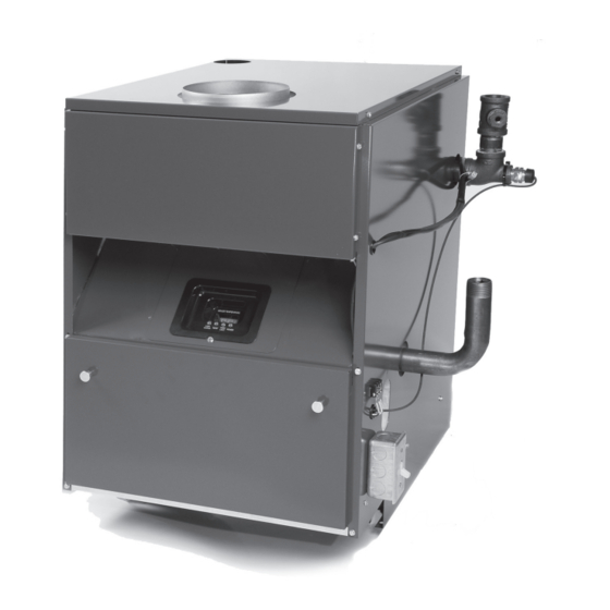
PWXL
Cast Iron Gas Fired
Hot Water Boilers
INSTALLATION, OPERATION &
MAINTENANCE MANUAL
DUNKIRK BOILERS
2210 Dwyer Avenue, Utica NY 13504-4729
Phone: (315) 797-1310 • Fax: (866) 432-7329
e-mail: info@ecrinternational.com
web site: www.ecrinternational.com
240007958 REV B [03/2011]
An ISO 9001-2008 Certified Company
P/N
Advertisement
Table of Contents

Related Manuals for Dunkirk PWXL


Summary of Contents for Dunkirk PWXL
- Page 1 PWXL Cast Iron Gas Fired Hot Water Boilers INSTALLATION, OPERATION & MAINTENANCE MANUAL DUNKIRK BOILERS 2210 Dwyer Avenue, Utica NY 13504-4729 Phone: (315) 797-1310 • Fax: (866) 432-7329 e-mail: info@ecrinternational.com web site: www.ecrinternational.com 240007958 REV B [03/2011] An ISO 9001-2008 Certified Company...
-
Page 2: Table Of Contents
TABLE OF CONTENTS Safety Symbols ........................... 3 Boiler Ratings and Capacities ......................4 Before You Start .......................... 5 Locating the Boiler ........................6 Combustion And Ventilation Air ..................... 7 System Piping ..........................8 System Piping ..........................9 Chimney and Vent Pipe Operation ....................11 Vent Damper Operation .......................12 Gas Supply Piping ........................14 Electrical Wiring .........................16... -
Page 3: Safety Symbols
SAFETY SYMBOLS The following defi ned symbols are used throughout this manual to notify the reader of potential hazards of varying risk levels. CAUTION DANGER Indicates a hazardous situation which, if not Indicates a hazardous situation which, if not avoided, may result in injury. avoided, WILL result in death, serious injury. -
Page 4: Boiler Ratings And Capacities
BOILER RATINGS AND CAPACITIES Table 1- Boiler Ratings and Capacities Natural or Propane Gas Dimensions Number of Boiler Heating Capacity Net I=B=R Flue Sections Input *MBH Dim. A *MBH+ Rating *MBH Diameter 5" 11-1/4" 6" 14-1/2" 6" 17-3/4" 7" 21" 7"... -
Page 5: Before You Start
BEFORE YOU START Where required by the authority having jurisdiction, the Check to be sure you have the right size boiler before installation must conform to the Standard for Controls and starting the installation. See rating and capacity table on Safety Devices for Automatically Fired Boilers, ANSI/ASME previous page. -
Page 6: Locating The Boiler
LOCATING THE BOILER Select level location as centralized with piping system, Equipment shall be installed in a location in which the and as near chimney as possible. facilities for ventilation permit satisfactory combustion of gas, proper venting, and maintenance of ambient Place crated boiler at selected location, remove crate temperature at safe limits under normal conditions of by pulling crate sides from top and bottom boards. -
Page 7: Combustion And Ventilation Air
COMBUSTION AND VENTILATION AIR Known Air Infi ltration Rate. See Table 1 for WARNING space with boiler only. Use equation for multiple appliances. Do not use an air infi ltration rate Air openings to combustion area must not (ACH) greater than 0.60. be obstructed. -
Page 8: System Piping
SYSTEM PIPING Place boiler in the selected location (as near chimney as In connecting the cold water supply to the water inlet valve, possible.) Your boiler is shipped assembled. You need make sure that a clean water supply is available. When the only to install the Relief Valve and a drain line to carry water supply is from a well or pump, a sand strainer should be installed at the pump. -
Page 9: System Piping
SYSTEM PIPING For Use With Cooling Units Figure 6 - Chilled Water Piping The boiler, when used in connection with a refrigeration system, must be installed so the chilled medium is Valves A & B - Open For Heating; Closed For Cooling piped in parallel with the boiler with appropriate valves Valves C &... - Page 10 SYSTEM PIPING Temperature/Pressure Gauge Installation NOTICE To install the temperature/pressure gauge on the boiler: IMPORTANT: DO NOT TIGHTEN GAUGE BY Remove the box containing the new gauge from the HAND!! Gauge should be tightened using a parts bag and remove the gauge from the box. crescent wrench or 9/16”...
-
Page 11: Chimney And Vent Pipe Operation
CHIMNEY AND VENT PIPE OPERATION Vent installations shall be in accordance with "Venting of NOTICE Equipment," of the National Fuel Gas Code, ANSI Z223.1/ NFPA 54, or applicable provisions of the local building Damper blade on furnished vent damper has codes. -
Page 12: Vent Damper Operation
CHIMNEY AND VENT PIPE CONNECTION Minimum Vent Pipe Clearance Place in operation the appliance being inspected. Follow the lighting instructions. Adjust thermostat so appliance Wood and other combustible materials must not be closer will operate continuously. than 6” from any surface of single wall metal vent pipe. Test for spillage at the draft hood relief opening after Listed Type B vent pipe or other listed venting systems 5 minutes of main burner operation. - Page 13 VENT DAMPER OPERATION Manual Operation Of The Vent Damper The vent damper must be inspected at least once a year by a trained, experienced service technician. The name of the The vent damper may be placed in the open position to person who originally installed your vent damper is shown permit burner operation by using the “HOLD DAMPER on the installation label.
-
Page 14: Gas Supply Piping
GAS SUPPLY PIPING General CAUTION • Use piping materials and joining methods acceptable WHAT TO DO IF YOU SMELL GAS to authority having jurisdiction. In absence of such requirements, follow National Fuel Gas Code, ANSI • Do not try to light any appliance. Z223.1/NFPA 54. - Page 15 GAS SUPPLY PIPING Leak Check Gas Piping Pressure test boiler and gas connections before placing boiler in operation. DANGER Fire Hazard. Do not use matches, candles, open fl ames, or other methods providing ignition source. Failure to comply will result in death or serious injury.
-
Page 16: Electrical Wiring
ELECTRICAL WIRING WARNING THERMOSTAT LOCATIONS TO AVOID Turn off electrical power at fuse box before DEAD SPOTS HOT SPOTS COLD SPOTS making any line voltage connections. Follow Concealed pipes Concealed pipes local electrical codes or ducts Behind doors Fireplace All electrical work must conform to local codes as well as TV sets Stairwells - draft s the National Electrical Code, ANSI/NFPA-70, latest revision. - Page 17 LECTRICAL IRING Figure 16-1 - Field Wiring Connections -Circulator Pump Wiring Th ermostat TW & TR Referenced on Page 15 AMPER ARNESS OTES AMPER SHIPPED LOOSE IN CRATE AMPER ARNESS MUST BE CONNECTED TO VENT WHEN MOUNTED...
- Page 18 ELECTRICAL WIRING Figure 16-2 - Wiring Diagram - Electronic Ignition NOTICE If any of the original wire as supplied with this appliance must be replaced, It must be replaced with type 105°C thermoplastic wire or it’s equivalent...
- Page 19 ELECTRICAL WIRING Figure 16-3 - Wiring Diagram - Standing Pilot NOTICE If any of the original wire as supplied with this appliance must be replaced, It must be replaced with type 105°C thermoplastic wire or it’s equivalent...
-
Page 20: Equipment And Optional Accessories
EQUIPMENT AND OPTIONAL ACCESSORIES Relief Valve Air Eliminating Fitting (Air Purger) You must have a relief valve on your boiler. Water An air purger is used to remove excess air from the expands as it is heated. If there is no place for the water system. -
Page 21: Starting The Boiler
EQUIPMENT AND OPTIONAL ACCESSORIES Blocked Vent Safety Shutoff down the fl ow of gas to the main burners by removing power to the gas valve. In the event that the blocked vent The blocked vent switch is a manual reset disc thermostat switch contacts open, the reset button on the back of the with a fi... - Page 22 STARTING THE BOILER Intermittent Ignition Boiler - VR8204A/VR8304M Gas Continuous Pilot Boiler - VR8200A/VR8300A Gas Valve Operating Instructions Valve Lighting Instructions STOP ! Read the WARNING on the previous page. STOP ! Read the WARNING on the previous page. Set the thermostat to lowest setting. Set the thermostat to lowest setting.
-
Page 23: Initial Operational Boiler Test Check-Out Procedure
INITIAL OPERATIONAL BOILER TEST CHECK-OUT PROCEDURE Cast Iron Gas-Fired Cast Iron Boilers Check off each step as completed. Verify base insulation is securely fastened to base panels. Verify air purged from hydronic heating system. Purge air from gas piping; check gas piping for leaks. Verify proper orifi... -
Page 24: Initial Operational Boiler Test Check-Out Certifi Cate & Signed Receipt
INITIAL OPERATIONAL BOILER TEST CHECK-OUT CERTIFICATE & SIGNED RECEIPT Boiler Manufacturer: Boiler Identifi cation: Model #: _______________________________________________ Serial #: ________________________________________________ Measured BTUh input: _____________________ Operational Test Date: ________ /________ /_________ • Installation Instructions in the Installation, Operation and Maintenance Manual have been followed. •... -
Page 25: Operating Your Boiler
OPERATING YOUR BOILER Automatic Gas Valve Figure 19- Lighting the Pilot The Automatic Gas Valve opens or closes according to the heat requirements of the thermostat and temperature limit control. It closes if the pilot goes out. Each individual con- trol must be operating correctly before any gas can pass to the burners. -
Page 26: Checking And Adjusting
CHECKING AND ADJUSTING Adjust Pilot Burner Check thermostat operation. When set above temperature indicated on the thermometer, boiler should ignite. Make Pilot fl ame should surround 3/8” to 1/2” of the pilot sensor, certain the thermostat turns off the boiler when room (Refer to Fig. -
Page 27: Sequence Of Operation
(water left in to freeze will crack the pipes and/or boiler). SEQUENCE OF OPERATION PWXL with Electronic Ignition The Boiler uses an electronic control to maintain water temperature and to monitor the critical water level. There... -
Page 28: Troubleshooting
Limit needs to be set at 170 F or lower. If the settings are overlapped then the control PWXL with Standing Pilot will not operate properly and the burner will Units with a standing pilot do not use an ignition module or switch off at the lower setting. -
Page 29: Service Hints
SERVICE HINTS You may avoid inconvenience and service calls by checking these points before you call for service. IF YOUR SYSTEM IS NOT HEATING OR NOT GIVING ENOUGH HEAT . . . Possible Cause What to do Thermostat is not set cor- Reset thermostat above room temperature rectly Burner is not operating... - Page 30 NOTES...
- Page 32 DUNKIRK BOILERS 2201 Dwyer Avenue, Utica NY 13504-4729 web site: www.ecrinternational.com...
Need help?
Do you have a question about the PWXL and is the answer not in the manual?
Questions and answers