
Related Manuals for Dunkirk PWXL


Summary of Contents for Dunkirk PWXL
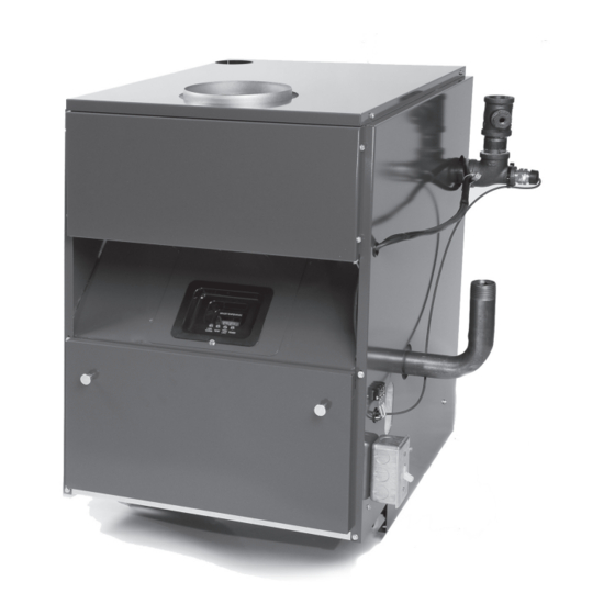
- Page 1 PWXL Cast Iron Gas Fired Hot Water Boilers INSTALLATION, OPERATION & MAINTENANCE MANUAL DUNKIRK BOILERS 85 Middle Rd. Dunkirk, NY 14048 www.dunkirk.com 240007958 REV A [09/09] An ISO 9001-2000 Certified Company...
-
Page 2: Table Of Contents
TABLE OF CONTENTS Safety Symbols................................4 Boiler Ratings and Capacities ..........................5 Before You Start ..............................6 Locating the Boiler ..............................7 Combustion And Ventilation Air ..........................8 System Piping ..............................11 Chimney and Vent Pipe Operation ........................13 Vent Damper Operation ............................14 Gas Supply Piping ..............................16 Electrical Wiring .............................. -
Page 3: Safety Symbols
SAFETy SymBOLS The following defined symbols are used throughout this manual to notify the reader of potential hazards of varying risk levels. CAUTION DANGER Indicates an imminently hazardous situation which, if not Indicates an imminently hazardous situation which, if not avoided, may result in injury or property damage. -
Page 4: Boiler Ratings And Capacities
BOiLEr rATiNgS ANd CApACiTiES Table 1- Boiler Ratings and Capacities Natural or Propane Gas Dimensions Number of Boiler Heating Capacity Net I=B=R Sections AGA Input *MBH Flue Diameter Dim. A *MBH+ Rating *MBH 5" 11-1/4" 6" 14-1/2" 6" 17-3/4" 7" 21"... -
Page 5: Before You Start
BEFOrE yOu STArT The installation must conform to the requirements of the authority Check to be sure you have the right size boiler before starting the having jurisdiction or, in the absence of such requirements, to the installation. See rating and capacity table on previous page. Also be National Fuel Gas Code, ANSI Z223.1-latest revision. -
Page 6: Locating The Boiler
LOCATiNg ThE BOiLEr Select level location as centralized with piping system, and as Equipment shall be installed in a location in which the facilities near chimney as possible. for ventilation permit satisfactory combustion of gas, proper venting, and maintenance of ambient temperature at safe limits Place crated boiler at selected location, remove crate by pulling under normal conditions of use. -
Page 7: Combustion And Ventilation Air
COmBuSTiON ANd VENTiLATiON Air Provision for combustion and ventilation air must be in accordance with the latest revision of the National Fuel Gas Code, ANSI Z223.1, or applicable provisions of the local building codes. You must provide for enough fresh air to assure proper combustion. The fire in the boiler uses oxygen. - Page 8 COmBuSTiON ANd VENTiLATiON Air All Air from Outdoors: The confined space shall communicate with the outdoors in accordance with methods A or B. The minimum dimension of air openings shall not be less than 3 in. Where ducts are used, they shall be of the same cross-sectional area as the free area of the openings to which they connect.
- Page 9 COmBuSTiON ANd VENTiLATiON Air Where communicating with the outdoors through horizontal ducts (see Figure 4), each opening shall have a minimum free area of 1 area of sq. in. per 2000 Btu per hour of total rating of all equipment in the enclosure. Figure 4 - Horizontal Ducts Communicating to the Outdoors Table 4 FRESh AIR DUCT CAPACITIES (1 Square inch per 2,000 Btuh)
-
Page 10: System Piping
SySTEm pipiNg Place boiler in the selected location (as near chimney as pos- Follow the mixing valve manufacturer’s installation instructions. sible.) Your boiler is shipped assembled. You need only to install The minimum design return water temperature to the boiler to the Relief Valve and a drain line to carry any water or steam to a prevent condensation in the boiler and venting is 120ºF. - Page 11 SySTEm pipiNg Temperature/Pressure Gauge Installation NOTICE IMPORTANT: DO NOT TIGHTEN GAUGE BY HAND!! To install the temperature/pressure gauge on the boiler: Gauge should be tightened using a crescent wrench or 9/16” open end wrench as shown in Figure 9 Remove the box containing the new gauge from the parts bag and remove the gauge from the box.
-
Page 12: Chimney And Vent Pipe Operation
ChimNEy ANd VENT pipE OpErATiON Boilers for connection to gas vents or chimneys, vent installations Connecting The Vent Damper And Vent Connector shall be in accordance with Part 7, Venting Equipment, of the Na- Refer to Table 1 (page 4) flue diagram for the size and location of tional Fuel Gas Code, ANSI Z2231 - latest revision, and applicable the vent (flue opening). -
Page 13: Vent Damper Operation
ChimNEy ANd VENT pipE CONNECTiON crawl space, double wall vent pipe should be used Where vent pipe spaces of the building. Turn on clothes dryers and any appli- passes through a combustible wall or partition, use a ventilated ance not connected to the common venting system. Turn on metal thimble. - Page 14 VENT dAmpEr OpErATiON Turn the thermostat or controller down again and check that For further information, and for a vent damper troubleshooting the damper position indicator returns to the closed position. guide, refer to the manual that was packaged with the vent damper. The vent damper must be inspected at least once a year by a trained, Manual Operation Of The Vent Damper experienced service technician.
-
Page 15: Gas Supply Piping
gAS SuppLy pipiNg Check Gas Supply Checking The Gas Piping The gas pipe to your boiler must be the correct size for the length Upon completion of piping, check immediately for gas leaks. Open of the run and for the total Btu per hour input of all gas utilization the manual shut-off valve. -
Page 16: Electric Power Supply
lEctrical iring Connect 24 Volt thermostat leads to the white (TW) and red (TR) WARNING wires located in service switch junction box, located on outer jacket Turn off electrical power at fuse box before making any of boiler see Fig.16-1 for service switch junction box and thermo- line voltage connections. -
Page 17: Electrical Wiring
lEctrical iring Figure 16-1 - Field Wiring Connections -Circulator Pump Wiring Thermostat TW & TR Referenced on Page 15 amper arness otes amper shippeD loose iN crate amper arNess must be coNNecteD to VeNt wheN mouNteD... - Page 18 ELECTriCAL WiriNg Figure 16-2 - Wiring Diagram - Electronic Ignition NOTICE If any of the original wire as supplied with this appliance must be replaced, It must be replaced with type 105°C thermoplastic wire or it’s equivalent...
- Page 19 ELECTriCAL WiriNg Figure 16-3 - Wiring Diagram - Standing Pilot NOTICE If any of the original wire as supplied with this appliance must be replaced, It must be replaced with type 105°C thermoplastic wire or it’s equivalent...
-
Page 20: Equipment And Optional Accessories
EquipmENT ANd OpTiONAL ACCESSOriES Relief Valve Main Air Vent For Down Flow Systems Or Diaphragm Type Expansion Tank You must have a relief valve on your boiler. Water expands as it is heated. If there is no place for the water to expand into, water pres- Before a system is filled with water, there is air in the pipes and sure will build up inside the boiler and system. -
Page 21: Starting The Boiler
EquipmENT ANd OpTiONAL ACCESSOriES of gas to the main burners by removing power to the gas valve. In the Blocked Vent Safety Shutoff event that the blocked vent switch contacts open, the reset button on The blocked vent switch is a manual reset disc thermostat with a the back of the switch will pop up. - Page 22 STArTiNg ThE BOiLEr Intermittent Ignition Boiler - VR8204A/VR8304M Gas Valve Continuous Pilot Boiler - VR8200A/VR8300A Gas Valve Operating Instructions Operating Instructions STOP ! Read the WARNING on the previous page. STOP ! Read the WARNING on the previous page. Set the thermostat to lowest setting. Set the thermostat to lowest setting.
-
Page 23: Initial Operational Boiler Test Check-Out Procedure
iNiTiAL OpErATiONAL BOiLEr TEST ChECk-OuT prOCEdurE Cast Iron Gas-Fired Cast Iron Boilers Check off each step as completed. Verify base insulation is securely fastened to base panels. Verify air purged from hydronic heating system. Purge air from gas piping; check gas piping for leaks. Verify proper orifices have been installed. -
Page 24: Initial Operational Boiler Test Check-Out Certificate & Signed Receipt
iNiTiAL OpErATiONAL BOiLEr TEST ChECk-OuT CErTiFiCATE & SigNEd rECEipT Boiler Manufacturer: Boiler Identification: Model #: _______________________________________________ Serial #: ________________________________________________ Measured BTUh input: _____________________ Operational Test Date: ________ /________ /_________ • Installation Instructions in the Installation, Operation and Maintenance Manual have been followed. •... -
Page 25: Operating Your Boiler
OpErATiNg yOur BOiLEr Automatic Gas Valve Figure 19- Lighting the Pilot The Automatic Gas Valve opens or closes according to the heat requirements of the thermostat and temperature limit control. It closes if the pilot goes out. Each individual control must be operat- ing correctly before any gas can pass to the burners. -
Page 26: Checking And Adjusting
ChECkiNg ANd AdjuSTiNg boiler gauge to check your settings. Make the adjustments according Adjust Pilot Burner to its readings. Pilot flame should surround 3/8” to 1/2” of the pilot sensor, (Refer Check thermostat operation. When set above temperature indicated to Fig. 21). If flame needs adjusting, do it as follows: on the thermometer, boiler should ignite. -
Page 27: Sequence Of Operation
SEquENCE OF OpErATiON The Boiler uses an electronic control to maintain water temperature PWXL with Electronic Ignition and to monitor the critical water level. There are four (4) LED indi- Upon a call for heat the room thermostat will close the Green cators that will display the mode of operation of the unit. -
Page 28: Troubleshooting
F then the Low Temperature Limit needs to be set at 170 F or lower. If the settings are PWXL with Standing Pilot overlapped then the control will not operate properly and the burner will switch off at the lower setting. -
Page 29: Service Hints
SErViCE hiNTS You may avoid inconvenience and service calls by checking these points before you call for service. IF YOUR SYSTEM IS NOT hEATING OR NOT GIVING ENOUGh hEAT . . . Possible Cause What to do Thermostat is not set correctly Reset thermostat above room temperature Burner is not operating properly Check flame. - Page 32 85 Middle Rd. Dunkirk, NY 14048...
Need help?
Do you have a question about the PWXL and is the answer not in the manual?
Questions and answers