TP-Link TL-SG105E User Manual
Gigabit easy smart switch
Hide thumbs
Also See for TL-SG105E:
- User manual (79 pages) ,
- Installation manual (56 pages) ,
- Mounting manual (5 pages)

Related Manuals for TP-Link TL-SG105E


Summary of Contents for TP-Link TL-SG105E
- Page 1 TL-SG105E/TL-SG108E/TL-SG108PE TL-SG1016DE/TL-SG1024DE Gigabit Easy Smart Switch REV1.0.3 1910011479...
- Page 2 Specifications are subject to change without notice. is a registered trademark of TP-LINK TECHNOLOGIES CO., LTD. Other brands and product names are trademarks or registered trademarks of their respective holders. No part of the specifications may be reproduced in any form or by any means or used to make any derivative such as translation, transformation, or adaptation without permission from TP-LINK TECHNOLOGIES CO., LTD.
- Page 3 Industry Canada Statement (For TL-SG105E/TL-SG108E/TL-SG108PE only) CAN ICES-3 (B)/NMB-3(B) BSMI Notice (For TL-SG105E/TL-SG108E/TL-SG108PE only) 安全諮詢及注意事項 請使用原裝電源供應器或只能按照本產品注明的電源類型使用本產品。 清潔本產品之前請先拔掉電源線。請勿使用液體、噴霧清潔劑或濕布進行清潔。 注意防潮,請勿將水或其他液體潑灑到本產品上。 插槽與開口供通風使用,以確保本產品的操作可靠並防止過熱,請勿堵塞或覆蓋開口。 請勿將本產品置放於靠近熱源的地方。除非有正常的通風,否則不可放在密閉位置中。 請不要私自打開機殼,不要嘗試自行維修本產品,請由授權的專業人士進行此項工作。 FCC STATEMENT (For TL-SG1016DE/TL-SG1024DE only) This equipment has been tested and found to comply with the limits for a Class A digital device, pursuant to part 15 of the FCC Rules.
-
Page 4: Safety Information
BSMI Notice (For TL-SG1016DE/TL-SG1024DE only) 安全諮詢及注意事項 請使用原裝電源供應器或只能按照本產品注明的電源類型使用本產品。 清潔本產品之前請先拔掉電源線。請勿使用液體、噴霧清潔劑或濕布進行清潔。 注意防潮,請勿將水或其他液體潑灑到本產品上。 插槽與開口供通風使用,以確保本產品的操作可靠並防止過熱,請勿堵塞或覆蓋開口。 請勿將本產品置放於靠近熱源的地方。除非有正常的通風,否則不可放在密閉位置中。 請不要私自打開機殼,不要嘗試自行維修本產品,請由授權的專業人士進行此項工作。 此為甲類資訊技術設備,于居住環境中使用時,可能會造成射頻擾動,在此種情況下,使用者會被 要求採取某些適當的對策。 Продукт сертифіковано згідно с правилами системи УкрСЕПРО на відповідність вимогам нормативних документів та вимогам, що передбачені чинними законодавчими актами України. Safety Information When product has power button, the power button is one of the way to shut off the product;... - Page 5 Explanation of the symbols on the product label Symbol Explanation AC voltage DC voltage RECYCLING This product bears the selective sorting symbol for Waste electrical and electronic equipment (WEEE). This means that this product must be handled pursuant to European directive 2012/19/EU in order to be recycled or dismantled to minimize its impact on the environment.
-
Page 6: Declaration Of Conformity
DECLARATION OF CONFORMITY For the following equipment: Product Description: Gigabit Easy Smart Switch Model No.: TL-SG105E/TL-SG108E/TL-SG108PE/TL-SG1016DE/TL-SG1024DE Trademark: TP-LINK We declare under our own responsibility that the above products satisfy all the technical regulations applicable to the product within the scope of Council Directives: Directives 2004 / 108 / EC, Directives 2006 / 95 / EC, Directives 2011/65/EU The above product is in conformity with the following standards or other normative documents:... -
Page 7: Table Of Contents
CONTENTS Package Contents ..........................1 Chapter 1 About this Guide ......................2 Intended Readers ......................2 Conventions ........................2 Overview of This Guide ....................2 Chapter 2 Introduction ........................4 Overview of the Switch ....................4 Appearance Description ....................4 2.2.1 Front Panel ...................... - Page 8 QoS Basic ........................34 Bandwidth Control ......................36 Storm Control ....................... 37 Appendix A: Specifications ......................39...
-
Page 9: Package Contents
One Gigabit Easy Smart Switch One power cord Two mounting brackets and other fittings (for TL-SG1016DE/TL-SG1024DE only) Installation Guide Resource TL-SG105E/TL-SG108E/TL-SG108PE/TL-SG1016DE/TL-SG1024DE switch, including: This User Guide • Easy Smart Configuration Utility.exe • Easy Smart Configuration Utility User Guide •... -
Page 10: Chapter 1 About This Guide
Chapter 1 About this Guide This User Guide contains information for setup and management of TL-SG105E/TL-SG108E/ TL-SG108PE/TL-SG1016DE/TL-SG1024DE Gigabit Easy Smart Switch. Please read this guide carefully before operation. 1.1 Intended Readers This Guide is intended for network managers familiar with IT concepts and network terminologies. - Page 11 Chapter 2 Introduction Introduces features, application appearance TL-SG105E/TL-SG108E/TL-SG108PE/TL-SG1016DE/TL-SG1024DE switch. Chapter 3 Login to the Switch Introduces how to log on to the Web management page. Chapter 4 System This module is used to configure system properties of the switch. Here mainly introduces: System Info: View device information and define the device ...
-
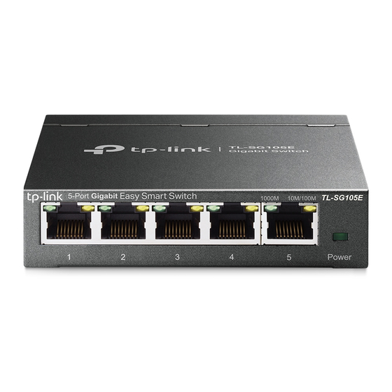
Page 12: Chapter 2 Introduction
Smart Configuration Utility in the Resource CD. 2.2 Appearance Description 2.2.1 Front Panel TL-SG105E/TL-SG108E The front panel of TL-SG105E is shown as Figure 2-1. Figure 2-1 Front Panel of TL-SG105E The front panel of TL-SG108E is shown as Figure 2-2. - Page 13 LEDs Name Status Indication Power is on. Power Flashing Power supply is abnormal. Power is off or power supply is abnormal. A 1000Mbps device is connected to the corresponding port. Data is being transmitted or received. Flashing 1000Mbps A 10/100Mbps device or no device is connected to the corresponding port.
- Page 14 The port is supplying power normally. Flashing The port is supplying power abnormally. PoE Status No PoE power supply is provided on the port. TL-SG1016DE/TL-SG1024DE The front panel of TL-SG1016DE is shown as Figure 2-4. Figure 2-4 Front Panel of TL-SG1016DE The front panel of TL-SG1024DE is shown as Figure 2-5.
-
Page 15: Rear Panel
2.2.2 Rear Panel TL-SG105E/TL-SG108E/TL-SG108PE The rear panel of TL-SG105E/TL-SG108E/TL-SG108PE features a power socket and a Kensington Security Slot (marked with ). TL-SG105E also has a Reset button located on the rear panel. Figure 2-6 Rear Panel of TL-SG105E Figure 2-7 Rear Panel of... - Page 16 Figure 2-9 Rear Panel of TL-SG1016DE Figure 2-10 Rear Panel of TL-SG1024DE Grounding Terminal: TL-SG105E/TL-SG108E/TL-SG108PE/TL-SG1016DE/TL-SG1024DE already comes with Lightning Protection Mechanism. You can also ground the switch through the PE (Protecting Earth) cable of AC cord or with Ground Cable.
-
Page 17: Chapter 3 Login To The Switch
Chapter 3 Login to the Switch 3.1 Login 1) To access the configuration utility, open a web-browser and type the default address http://192.168.0.1 in the address field of the browser, then press the Enter key. Figure 3-1 Web-browser Tips: To log in to the switch, the IP address of your PC should be set in the same subnet addresses of the switch. - Page 18 Figure 3-3 Main Setup-Menu Note: Clicking Apply can only make the new configurations effective before the switch is rebooted. If you want to keep the configurations effective even the switch is rebooted, please click Save Config. You are suggested to click Save Config before cutting off the power or rebooting the switch to avoid losing the new configurations.
-
Page 19: Chapter 4 System
Chapter 4 System The System module is mainly for basic settings of the switch, including four submenus: System Info, IP Setting, User Account and System Tools. 4.1 System Info On this page you can view the system information and define the device description. Choose the menu System→System Info to load the following page. -
Page 20: User Account
Choose the menu System→IP Setting to load the following page. Figure 4-2 IP Address Setting The following entries are displayed on this screen: IP Address Setting Allows you to enable or disable the switch to serve as DHCP DHCP Setting: client. -
Page 21: System Tools
Figure 4-3 User Account Setting You are kindly suggested to retype the new password in "Confirm Password" box instead of copying in order to avoid mistakes. Note: 1. The length of user name and password should not be more than 16 characters using digits, English letters and underlines only. -
Page 22: System Reboot
The following entries are displayed on this screen: Config Backup Click the Backup Config button to save the current configuration Backup Config: as a file to your computer. You are suggested to take this measure before upgrading. Config Restore ... -
Page 23: Firmware Upgrade
4.4.4 Firmware Upgrade The switch system can be upgraded via the Web management page. To upgrade the system is to get more functions and better performance. Go to http://www.tp-link.com to download the updated firmware. Choose the menu System→System Tools→Firmware Upgrade to load the following page. -
Page 24: Chapter 5 Switching
Chapter 5 Switching Switching module is used to configure the basic functions of the switch, including three submenus: Port Setting, IGMP Snooping and Port Trunk. 5.1 Port Setting On this page, you can configure and view the basic parameters of each port, including the port status, speed, duplex mode and flow control. -
Page 25: Igmp Snooping
Allows you to enable or disable the port. “Enable" indicates that Status: the port is operational and "Disable" indicates the port is non-operational. If a port is unused for a long time, its status can be set to “Disable” to cut down the energy cost. Select the Speed and Duplex mode for the port. -
Page 26: Port Trunk
The following entries are displayed on this screen: IGMP Snooping Enable or disable IGMP snooping function globally on the switch. IGMP Snooping: Enable or disable Report Message Suppression function globally. Report Message If this function is enabled, the first Report Message from the Suppression listener will forward to the router ports while the subsequent Report Message will be suppressed to reduce the IGMP packets. - Page 27 Choose the menu Switching→Port Trunk to load the following page. Figure 5-3 Trunk Group Setting Here you can configure and view the port parameters. Trunk Group Setting Select an identified number for the trunk group from the Group ID: drop-down list.
-
Page 28: Chapter 6 Monitoring
Chapter 6 Monitoring Monitoring module monitors the traffic information of the switch, and provides the convenient method to locate and solve the network problem, includes four submenus: Port Statistics, Port Mirror, Cable Test and Loop Prevention. 6.1 Port Statistics On this page you can view the statistic information of each port, which facilitates you to monitor the traffic and locate faults promptly. -
Page 29: Port Mirror
Displays the number of error packets received on the port. RxBadPkt: 6.2 Port Mirror Port mirror functions to monitor and mirror network traffic by forwarding copies of incoming and outgoing packets from one/multiple ports (mirrored port) to a specific port (mirroring port). Usually, the mirroring port is connected to a data diagnosis device, which is used to analyze the mirrored packets for monitoring and troubleshooting the network. -
Page 30: Cable Test
The following entries are displayed on this screen: Port Mirror Allows you to enable or disable the port mirror feature of the Port Mirror: specified port. Select a port from the pull-down list as the mirroring port. Mirroring Port: Mirrored Port ... -
Page 31: Loop Prevention
Figure 6-3 Cable Test The following entries are displayed on this screen: Cable Test Click the check box to select the desired port for cable test. It is Select: multi-optional. Displays the port number of the switch. Port: Displays the connection status of the cable connected to the port. Test Result: The test results of the cable include “No Cable”, “Open”, “Short”, ”Open Short”, “Normal”, “Cro Cable”... - Page 32 Choose the menu Monitoring→Loop Prevention to load the following page. Figure 6-4 Loop Function Setting The following entries are displayed on this screen: Loop Prevention Setting Allows you to enable or disable loop prevention function globally. Loop Prevention:...
-
Page 33: Chapter 7 Vlan
Chapter 7 VLAN The traditional Ethernet is a data network communication technology based on CSMA/CD (Carrier Sense Multiple Access/Collision Detect) via shared communication medium. Through the traditional Ethernet, the overfull hosts in LAN will result in serious collision, flooding broadcasts, poor performance or even breakdown of the Internet. -
Page 34: Mtu Vlan
There are 3 types of VLAN modes supported in the switch: 1. MTU VLAN MTU VLAN (Multi-Tenant Unit VLAN) defines an uplink port which will build up several VLANs with each of the other ports. Each VLAN contains two ports, the uplink port and one of the other ports in the switch, so the uplink port can communicate with any other port but other ports cannot communicate with each other. -
Page 35: Port Based Vlan
Choose the menu VLAN→MTU VLAN to load the following page. Figure 7-3 MTU VLAN Configuration Note: The uplink port will form several VLANs with each of the other ports. Each VLAN contains two ports, the uplink port and one of the other ports in the switch, thus the uplink port can communicate with any other port but other ports cannot communicate with each other. -
Page 36: 802.1Q Vlan
To ensure the normal communication of the factory switch, the default VLAN of all ports is set to VLAN1. VLAN 1 cannot be deleted. The following entries are displayed on this screen: Port Based VLAN Configuration Enable or disable Port Based VLAN mode. Port Based VLAN Configuration: Enter the ID number of VLAN. - Page 37 Figure 7-5 802.1Q VLAN Configuration To ensure the normal communication of the factory switch, the default VLAN of all ports is set to be VLAN1. VLAN 1 cannot be modified or deleted. The following entries are displayed on this screen: 802.1Q VLAN Configuration ...
-
Page 38: 802.1Q Pvid Setting
Click the check box to configure the egress rule of the traffic on Tagged: this port as tagged. The switch adds the tag header before sending the packet. Click the check box to exclude the port from the current VLAN. Not Member: 7.4 802.1Q PVID Setting PVID (Port Vlan ID) is the default VID of the port. - Page 39 The following entries are displayed on this screen: 802.1Q VLAN Port Setting Select: Select the desired port for configuration. It is multi-optional. Port: Displays the port number. PVID: Enter a PVID number for the port. When adding the tag header to the received untagged packet, the switch will automatically uses this PVID value as the VLAN ID of the added tag.
-
Page 40: Chapter 8 Qos
Chapter 8 QoS QoS (Quality of Service) functions to provide different quality of service for various network applications and requirements and optimize the bandwidth resource distribution so as to provide a network service experience of a better quality. This switch classifies the ingress packets, maps the packets to different priority queues and then forwards the packets according to weighted round robin (WRR) scheduling algorithm to implement QoS function. - Page 41 with higher priority, and only when the queue with higher priority is empty, packets in the queue with lower priority are sent. 2. 802.1P Based Figure 8-2 802.1Q frame As shown in the figure above, each 802.1Q Tag has a Pri field, comprising 3 bits. The 3-bit priority field is 802.1p priority in the range of 0 to 7.
-
Page 42: Qos Basic
DSCP priority in the range of 0 to 63. The last 2 bits (bit 6 and bit 7) are reserved. The mapping relationship between sixty-four DSCP priority value and priority queues is shown as follows: Priority 0 to 15 are assigned to the 1 (Lowest) priority queue. ... - Page 43 Figure 8-5 QoS Basic The following entries are displayed on this screen: Global Config Select the desired QoS mode. QoS Mode: • Port Based: The switch classifies the ingress packets and maps the packets to different priority queues based on which port the packets come from.
-
Page 44: Bandwidth Control
Specify the priority queue the packets from the port are mapped Priority Queue: to. The priorities are labeled as 1~4 and among them the bigger the value, the higher the priority. 8.2 Bandwidth Control Bandwidth control functions to control the ingress/egress traffic rate on each port via configuring the available bandwidth of each port. -
Page 45: Storm Control
Here you can configure the port egress rate limit. If the rate for Egress Rate(Kbps): sending packets on the port exceeds the set rate, the packets will be discarded. Note: A port cannot enable both Storm Control and Ingress Rate Control at the same time. When egress bandwidth control feature is enabled for one or more ports, you are suggested to disable the flow control on each port to ensure the switch works normally. - Page 46 The following entries are displayed on this screen: Storm Control Setting Port: Select the desired port for storm control configuration. It is multi-optional. Status: Allows you to enable or disable the storm control function. Total Rate(Kbit/sec): Select the rate for receiving packets on the port. The packet traffic exceeding the rate will be discarded.
-
Page 47: Appendix A: Specifications
100Base-TX: UTP/STP of Cat. 5 or above Transmission Medium 1000Base-T: 4-pair UTP (≤100m) of Cat. 5, Cat. 5e, Cat.6 or above For TL-SG105E/ TL-SG108E: Power, 10/100Mbps,1000Mbps For TL-SG108PE: Power, PoE Max , Link/Act(Port 1- 8), PoE Status(Port 1- 4) For TL-SG1016DE/ TL-SG1024DE:... - Page 48 Operating Temperature: 0℃ ~ 40℃ Storage Temperature: -40℃ ~ 70℃ Operating Operating Humidity: 10% ~ 90% RH Non-condensing Environment For TL-SG105E/ TL-SG108E/ TL-SG108PE: Storage Humidity: 5% ~ 95% RH Non-condensing For TL-SG1016DE/ TL-SG1024DE: Storage Humidity: 5% ~ 90% RH Non-condensing Return to CONTENTS...