Table of Contents
Advertisement
HYDROBOX
SERVICE MANUAL
[Model name]
EHSC-VM2B
HYDROBOX
[Service Ref.]
EHSC-VM2B.UK
EHSC-VM6B.UK
EHSC-YM9B.UK
EHSC-TM9B.UK
EHSC-VM6EB.UK
EHSC-YM9EB.UK
EHPX-VM2B.UK
EHPX-VM6B.UK
EHPX-YM9B.UK
ERSC-VM2B.UK
R410A
CONTENTS
1. REFERENCE MANUAL ................................... 2
2. SAFETY PRECAUTION ................................... 3
3. SPECIFICATIONS ............................................ 6
4. PART NAMES AND FUNCTIONS .................. 7
5. OUTLINES AND DIMENSIONS ...................... 11
6. WIRING DIAGRAM ........................................ 13
7. FIELD WIRING ............................................... 24
8. WATER SYSTEM DIAGRAM ......................... 28
9. CONTROLS ................................................... 31
10. TROUBLESHOOTING ................................... 51
11. DISASSEMBLY PROCEDURE ...................... 68
12. SUPPLEMENTARY INFORMATION ............. 82
13. SERVICE AND MAINTENANCE ................... 83
PARTS CATALOG (OCB532)
January 2013
No. OCH532
REVISED EDITION-A
Revision:
• EHSC-VM2B.UK
and EHSC-TM9B.UK
have been added in
REVISED EDITION-A.
• Some descriptions have
been modified.
Please void OCH532.
•
Note:
• This manual describes
only service data of
Hydrobox.
• RoHS compliant prod-
ucts have <G> mark on
the spec name plate.
Advertisement
Table of Contents
Troubleshooting

Related Manuals for Mitsubishi Electric EHSC-VM2B


Summary of Contents for Mitsubishi Electric EHSC-VM2B
-
Page 1: Service Manual
HYDROBOX January 2013 No. OCH532 REVISED EDITION-A SERVICE MANUAL R410A [Model name] [Service Ref.] Revision: EHSC-VM2B.UK • EHSC-VM2B.UK EHSC-VM2B and EHSC-TM9B.UK have been added in EHSC-VM6B.UK EHSC-VM6B REVISED EDITION-A. • Some descriptions have EHSC-YM9B.UK been modified. EHSC-YM9B Please void OCH532. -
Page 2: Reference Manual
REFERENCE MANUAL OUTDOOR UNIT'S SERVICE MANUAL Service Ref. Service Manual No. PUHZ-RP35/50/60/71VHA4 PUHZ-RP35/50/60/71VHA4R4 PUHZ-RP100/125/140VKA OCH451 PUHZ-RP100/125/140YKA PUHZ-RP100/125/140YKAR4 PUHZ-HRP71/100VHA PUHZ-HRP71/100VHA2 PUHZ-HRP71/100VHA2R1 PUHZ-HRP100VHA2R2 OCH425 PUHZ-HRP100/125YHA PUHZ-HRP100/125YHA2 PUHZ-HRP100/125YHA2R1 PUHZ-W50/85VHA(-BS) PUHZ-W50/85VHAR1(-BS) OCH439 PUHZ-W50VHAR2(-BS) PUHZ-W85VHA2.UK OCH465 PUHZ-W85VHA2-BS.UK PUHZ-HW112/140YHA(-BS) PUHZ-HW112/140YHA2(-BS) PUHZ-HW112/140YHA2R1(-BS) PUHZ-HW112/140YHA2R3(-BS) PUHZ-HW140VHA(-BS) OCH439 PUHZ-HW140VHA2(-BS) PUHZ-HW140VHA2R1(-BS) PUHZ-HW140VHA2R2-BS PUHZ-HW140VHA2R3(-BS) PUHZ-SW40/45VHA(-BS) -
Page 3: Safety Precaution
Do not position furniture or electrical appliances below the outdoor unit or hydrobox. The discharge pipework from the emergency/safety devices of the hydrobox should be installed according to local law. Only use accessories and replacement parts authorised by Mitsubishi Electric ask a qualifi ed technician to fi t the parts. Electrical All electrical work should be performed by a qualifi... - Page 4 WARNING (SPLIT MODELS ONLY) Do not discharge refrigerant into the atmosphere if refrigerant leaks during installation, ventilate the room. Use appropriate tools for high pressure refrigerant. When pumping down refrigerant , stop the compressor before disconnecting the refrigerant pipes. During installation securely fasten the refrigerant pipes before starting the compressor. Check that refrigerant gas does not leak after the completion of installation.
- Page 5 [1] Cautions for service (1) Perform service after recovering the refrigerant left in unit completely. (2) Do not release refrigerant in the air. (3) After completing service, charge the cycle with specified amount of refrigerant. (4) When performing service, install a filter drier simultaneously. Be sure to use a filter drier for new refrigerant.
-
Page 6: Specifications
SPECIFICATIONS OCH532A... -
Page 7: Part Names And Functions
PART NAMES AND FUNCTIONS <EHSC-*M*B> (Split model system) Number Component Control and electrical box Main controller Manometer Expansion vessel Expansion vessel charge valve Automatic air vent Booster heater Drain cock Water circulation pump Pressure relief valve Flow switch Plate heat exchanger Strainer valve Inlet from space heating/Indirect DHW tank (pri- mary return) - Page 8 <EHSC-*M*EB> (Split model system without expansion vessel) Number Component Control and electrical box Main controller Manometer Automatic air vent Booster heater Drain cock Water circulation pump Pressure relief valve Flow switch Plate heat exchanger Strainer valve Inlet from space heating/Indirect DHW tank (pri- mary return) Outlet to space heating/Indirect DHW tank (primary fl...
- Page 9 <EHPX> (Packaged model system) Number Component Control and electrical box Main controller Manometer Expansion vessel Expansion vessel charge valve Automatic air vent Booster heater Drain cock Water circulation pump Pressure relief valve Flow switch Strainer valve Inlet from space heating/Indirect DHW tank (pri- mary return) Inlet from heat pump Outlet to heat pump...
- Page 10 <ERSC> (Split model system for heating and cooling) Number Component Control and electrical box Main controller Manometer Expansion vessel Expansion vessel charge valve Automatic air vent Booster heater Drain cock Water circulation pump Pressure relief valve Flow switch Plate heat exchanger Strainer valve Drain pan Inlet from space heating/Indirect DHW tank (pri-...
-
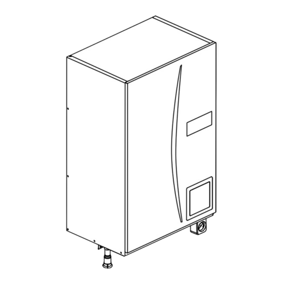
Page 11: Outlines And Dimensions
OUTLINES AND DIMENSIONS 5-1. Technical Drawings (Unit: mm) <EHSC> (Split model system) Automatic air vent Earth leakage circuit breaker Terminal block Pressure relief Main controller valve 233) <Front> <Side> <Rear> Letter Pipe description Connection size/type Space heating/Indirect DHW 28 mm/Compression tank (primary) return connection Space heating/Indirect DHW 28 mm/Compression... - Page 12 <ERSC> (Split model system) Automatic air vent Earth leakage circuit breaker Terminal block Pressure relief Main controller valve (233) <Rear> <Right side> <Front> Letter Pipe description Connection size/type Space heating and cooling/ Indirect DHW tank (primary) G1 nut return connection Space heating and cooling/ Indirect DHW tank (primary) fl...
-
Page 13: Wiring Diagram
WIRING DIAGRAM 6-1. EHSC-VM2B Cylinder unit powered Cylinder unit powered by independent source. via outdoor unit Power supply to Booster heater To outdoor To outdoor Power supply ~/N 230V 50Hz unit unit ~/N 230V 50Hz ECB1 CN01 (BLK) Signal output... - Page 14 6-2. EHSC-VM6B Cylinder unit powered Cylinder unit powered by independent source. via outdoor unit Power supply to Booster heater To outdoor To outdoor Power supply ~/N 230V 50Hz unit unit ~/N 230V 50Hz ECB1 CN01 (BLK) Signal output (Boiler) BHCP CNPWM (WHT) TBO.1...
- Page 15 6-3. EHSC-YM9B Cylinder unit powered Cylinder unit powered by independent source. via outdoor unit Power supply to Booster heater To outdoor To outdoor Power supply 3~ 400V 50Hz unit unit ~/N 230V 50Hz ECB1 CN01 (BLK) 2 4 6 Signal output (Boiler) BHCP...
- Page 16 6-4. EHSC-TM9B Cylinder unit powered Cylinder unit powered by independent source. via outdoor unit Power supply To outdoor To outdoor Power supply to Booster heater unit ~/N 230V 50Hz unit 3~ 230V 50Hz ECB1 CN01 (BLK) 2 4 6 Signal output (Boiler) BHCP...
- Page 17 6-5. EHSC-VM6EB Cylinder unit powered Cylinder unit powered by independent source. via outdoor unit Power supply to Booster heater To outdoor To outdoor Power supply ~/N 230V 50Hz unit unit ~/N 230V 50Hz ECB1 CN01 (BLK) Signal output (Boiler) BHCP CNPWM (WHT) TBO.1...
- Page 18 6-6. EHSC-YM9EB Cylinder unit powered Cylinder unit powered by independent source. via outdoor unit Power supply to Booster heater To outdoor Power supply To outdoor 3~ 400V 50Hz unit ~/N 230V 50Hz unit ECB1 CN01 (BLK) 2 4 6 Signal output (Boiler) BHCP...
- Page 19 6-7. EHPX-VM2B Cylinder unit powered Cylinder unit powered by independent source. via outdoor unit Power supply to Booster heater To outdoor Power supply To outdoor ~/N 230V 50Hz unit unit ~/N 230V 50Hz ECB1 CN01 (BLK) Signal output (Boiler) BHCP CNPWM (WHT) TBO.1...
- Page 20 6-8. EHPX-VM6B Cylinder unit powered Cylinder unit powered by independent source. via outdoor unit Power supply to Booster heater To outdoor To outdoor Power supply ~/N 230V 50Hz unit unit ~/N 230V 50Hz ECB1 CN01 (BLK) Signal output (Boiler) BHCP CNPWM (WHT) TBO.1...
- Page 21 6-9. EHPX-YM9B Cylinder unit powered Cylinder unit powered by independent source. via outdoor unit Power supply to Booster heater To outdoor Power supply To outdoor 3~ 400V 50Hz unit ~/N 230V 50Hz unit ECB1 CN01 (BLK) 2 4 6 Signal output (Boiler) BHCP...
- Page 22 6-10. ERSC-VM2B Cylinder unit powered Cylinder unit powered by independent source. via outdoor unit Power supply to Booster heater To outdoor To outdoor Power supply ~/N 230V 50Hz unit unit ~/N 230V 50Hz ECB1 CN01 (BLK) Signal output (Boiler) BHCP CNPWM (WHT) TBO.1...
-
Page 23: Dip Switch Setting
6-11. Dip switch setting Located on the FTC4 printed circuit board are 4 sets of small white switches known as Dip switches. The Dip switch number is printed on the circuit board next to the relevant switches. The word ON is printed on the circuit board and on the Dip switch block itself. -
Page 24: Field Wiring
FIELD WIRING Breaker abbreviation Meaning ECB1 Earth leakage circuit breaker for booster heater Terminal block 1 Option 1: Hydrobox powered via outdoor unit <1 phase> Hydrobox Outdoor unit To control board Power Wiring Earth supply circuit leakage breaker or 230V circuit Isolating 50Hz... - Page 25 <3 phase> Hydrobox Outdoor unit To control board Power supply Earth Wiring leakage circuit 400V circuit breaker or 50Hz breaker Isolating switch ECB1 booster heater Wiring Power supply (Primary circuit) circuit 3~ 400 V 50 Hz (EH**-YM9(E)B) breaker or 3~ 230 V 50 Hz (EHSC-TM9B) Isolating switch *1 If the installed earth leakage circuit breaker does not have an over-current protection function, install a breaker with that function along the same...
- Page 26 Option2: Hydrobox powered by independent source If the hydrobox and outdoor units have separate power supplies, the following requirements MUST be carried out: Black Initial settings CN01 • Change connector connections in hydrobox control and electrical box (Power supplied Hydrobox by outdoor unit) (see Figure 7-3).
- Page 27 <3 phase> Hydrobox Power supply Wiring Earth leakage circuit 230V circuit breaker or 50Hz breaker Isolating switch Outdoor unit To control board Power supply Wiring Earth circuit leakage 400V breaker or circuit 50Hz Isolating breaker switch ECB1 booster Wiring heater Power supply circuit (Primary circuit)
-
Page 28: Water System Diagram
WATER SYSTEM DIAGRAM Refrigerant pipe <EHSC> (Split model system) Water pipe <ERSC> (Split model system for heating and cooling) Plate heat exchanger Flexible hose Cold Hydrobox Booster heater 1,2 water Drain cock (booster heater) Pump valve Water circulation pump 1 Manometer Pressure relief valve Automatic air vent... - Page 29 Local system 1-zone temperature control Zone1 Zone1 2-zone temperature control Zone1 Zone2 1-zone temperature control with boiler 2-zone temperature control with boiler Zone1 Zone1 Zone2 1. Zone1 heat emitters (e.g. radiator, fan coil unit) (fi eld supply) 2. Mixing tank (fi eld supply) 3.
- Page 30 Filling the System (Primary Circuit) 1. Check all connections including factory fi tted ones are tight. 2. Insulate pipe work between hydrobox and outdoor unit. 3. Thoroughly clean and fl ush, system of all debris. (Refer to 4.2 in the installation manual.) 4.
-
Page 31: Controls
CONTROLS 9-1. Main Controller <Main controller parts> Letter Name Function Screen Screen in which all information is displayed Menu Access to system settings for initial set up and modifi cations. Back Return to previous menu. Confi rm Used to select or save. (Enter key) Power/Holiday If system is switched off pressing once will turn system on. - Page 32 <Main Controller Menu Tree> Unrestricted access Initial Installer only Main screen Shaded items relate Information to DHW functions. Option These are only avail- Forced DHW ON/OFF able if the system ON/Prohibited/Timer includes a DHW tank. Heating/Cooling ON/Prohibited/Timer Holiday Active/Non active Set time Main menu Normal/Eco...
- Page 33 <Main Controller Menu Tree> Unrestricted access Initial Installer only Main screen Shaded items relate to DHW functions. Main menu Service These are only avail- (Password protected) able if the system Manual operation includes a DHW tank. Function settings Thermistor adjustment Auxiliary settings Economy setting for pump ON/OFF...
-
Page 34: Service Menu
9-2. Service Menu The service menu provides functions for use by installer or service engineer. It is NOT intended the home owner alters settings within this menu. It is for this reason password protection is required to prevent unauthorised access to the service settings. -
Page 35: Function Settings
Function settings Function Setting allows the setting of auto recovery after power failure only. 1. From the service menu use F1 and F2 to highlight Function Setting. 2. Press CONFIRM. 3. Ensure the Ref address and unit number are displayed to the right. 4. - Page 36 <Electric heater (Heating)> From the Auxiliary settings menu highlight Electric heater (Heating). Press CONFIRM. The Electric heater (Heating) screen is displayed. Press F1 button to switch the function ON/OFF. Use F3 and F4 buttons to adjust the time period of heat pump only operation before the booster heater will assist in space heating.
- Page 37 Heat source setting The default heat source setting is heat pump and all electric heaters present in the system to be operational. This is referred to as Standard operation on the menu. Heat From the service menu use F1 and F2 buttons to scroll through list until Source Setting is highlighted.
- Page 38 <Cold weather function> For extremely low outdoor ambient temperature conditions when the heat pump’s capacity is restricted the heating or DHW is provided only by the electric booster heater (and immersion if present). This function is intended for use during extreme cold periods only.
- Page 39 <Floor dry up function> The Floor dry up function automatically changes the target hot water temperature in stages to gradually dry concrete when this particular type of underfl oor heating system is installed. 1. Turn off the system using the main controller. 2.
- Page 40 Running information This function shows current temperature and other data of main component parts of both the indoor and outdoor units. 1. From the Service menu highlight Running information. 2. Press CONFIRM. 3. Press F3 and F4 buttons to set the Ref. address. *1 4.
-
Page 41: Password Protection
Password protection Password protection is available to prevent unauthorised access to the service menu by untrained persons. From the service menu use F1 and F2 buttons to scroll through list until is highlighted. Press CONFIRM. When password input screen is displayed use buttons F1 and F2 to move left and right between the four digits, F3 to lower the selected digit by 1, and F4 to increase the selected digit by 1. - Page 42 SD card The use of an SD memory card simplifi es the main controller settings in the fi eld. *Ecodan service tool (for use with PC tool) is necessary for the setting. <SD Main RC> From the SD card setting use F1 and F2 buttons to scroll through list until “SD Main RC”...
- Page 43 <Table 9-2-1> Request Request content Range Unit code Error history 1 (latest) Displays error history. ("– –" is displays if no history is present.) Code Error history 2 (second to last) Displays error history. ("– –" is displays if no history is present.) —...
- Page 44 Indoor unit switch setting display (Request code: 162 to 165) 0: OFF 1: ON 0: OFF 1: ON SW1, SW2, SW3, SW4 SW1, SW2, SW3, SW4 Display Display 00 00 00 40 00 01 00 41 00 02 00 42 00 03 00 43 00 04...
- Page 45 Indoor unit switch setting display (Request code: 162 to 165) 0: OFF 1: ON 0: OFF 1: ON SW1, SW2, SW3, SW4 SW1, SW2, SW3, SW4 Display Display 00 80 00 C0 00 81 00 C1 00 82 00 C2 00 83 00 C3 00 84...
- Page 46 Output signal display (Request code: 175/553) Please refer to Table 2 on relevant wiring diagram whilst using the following. 0: OFF 1: ON 0: OFF 1: ON Display Display xx 40 xx 00 xx 01 xx 41 xx 02 xx 42 xx 43 xx 03 xx 04...
- Page 47 Output signal display (Request code: 175/553) Please refer to Table 2 on relevant wiring diagram whilst using the following. 0: OFF 1: ON 0: OFF 1: ON Display Display xx C0 xx 80 xx C1 xx 81 xx C2 xx 82 xx C3 xx 83 xx C4...
- Page 48 Output signal display (Request code: 175/553) Mixing valve state Please refer to Table 2 on relevant wiring diagram whilst using the following. Mixing valve state 0: OFF 1: ON Stop Display Stop Open 00 xx Close 01 xx 02 xx 03 xx 04 xx 05 xx...
- Page 49 Input signal display (Request code: 176/554) Please refer to Table 1 on relevant wiring diagram whilst using the following. 0: OFF (open) 1: ON (short) 0: OFF (open) 1: ON (short) Display Display 00 00 00 40 00 01 00 41 00 02 00 42 00 03...
- Page 50 <Emergency operation (Heater)> In Emergency operation mode the outdoor heat pump unit will not operate. Heat- ing for DHW and space heating is provided by the booster heater and the tank immersion heater (if installed). Space heating flow temp is restricted 40°C if an immersion heater is not present on the DHW tank then the booster heater will also indirectly heat the DHW.
-
Page 51: Troubleshooting
TROUBLESHOOTING 10-1. Troubleshooting <Summary of self diagnosis based on Error Codes and Service Procedures> Present and past Error codes are logged and displayed on the main controller or control board of the outdoor unit. Please refer to the table below and subsequent explanations to diagnose and remedy typical problems that may occur in the fi eld. Unit Condition Error Code Action... - Page 52 10-4. Self diagnosis and action Check if Dip SW is set correctly. (Refer to Chapter 6-11.) Error code Title and display conditions Possible Cause Diagnosis and action Circulation water temperature overheat Insuffi cient system head Refer to table in section 10-6. to determine if protection system pump meets requirements.
- Page 53 Error code Title and display conditions Possible Cause Diagnosis and action P1/P2/L5/LD Indoor unit temperature thermistor failure Connector/terminal wire has become Visually check the terminals and connec- * The thermistors subject to failure can be detached or loose wiring. tions and reattachas appropriate. checked in “Request code: 567”...
- Page 54 Error code Title and display conditions Possible Cause Diagnosis and action Heating operation error THW1 has become detached from its Visually inspect location and reattach as * “3” is displayed in “Request code: 567” in “Run- holder. necessary. ning information”. <Heating/FS>...
- Page 55 Error code Title and display conditions Possible Cause Diagnosis and action Low primary circuit (Zone2 side) fl ow rate Insuffi cient system head If more head required either add an pump of the same size or replace existing pump. detected by fl ow switch * “3”...
- Page 56 Error code Title and display conditions Possible Cause Diagnosis and action <Defrosting> <Defrosting> THW2 detects a temperature ≤15ºC and TH2 1. Reduced water fl ow 1., 2. Check water piping. detects a temperature ≤−16ºC for consecutive 10 • Clogged fi lter seconds.
- Page 57 Error code Title and display conditions Possible Cause Diagnosis and action E1/E2 1. Fault with the main controller circuit 1. Replace main controller circuit board. Main controller control board failure board Error code E1 displayed if main controller can not access it's non volatile (non power dependent) memory.
- Page 58 10-5. Troubleshooting by inferior phenomena Fault symptom Possible cause Explanation - Solution Main controller display 1. There is no power supply to main 1. Check LED2 on FTC4. (See <Figure 5.2.1 in installation manual>.) is blank. controller. (i) When LED2 is lit. Check for damage or contact failure of the main controller wiring.
- Page 59 Contact your Mitsubishi Electric dealer. 7. Immersion heater cut-out tripped. 7. Check immersion heater thermostat and press reset button, located on im- mersion heater boss, if safe.
- Page 60 Contact your Mitsubishi Electric dealer. 5. Immersion heater cut-out has been triggered. 5. Check immersion heater thermostat and press reset button if safe. If the heater kept running with no water inside, this may have resulted in failure, so replace it with a new one.
- Page 61 Fault symptom Possible cause Explanation - Solution In 2-zone tempera- When Zone1 and Zone2 are both in heating Normal action no action necessary. ture control, only mode, the hot water temperature in Zone2 Zone2 does not does not exceed that in Zone1. reach the set tem- Faulty wiring of motorized mixing valve Refer to "5.3 Wiring for 2-zone temperature control"...
-
Page 62: Annual Maintenance
Recover Annual Maintenance It is essential that the hydrobox is serviced at least once a year by a qualifi ed individual any spare parts required MUST be purchased from Mitsubishi Electric (safety matter). NEVER bypass safety devices or operate the unit without them being fully operational. - Page 63 10-6. Checking Component Parts' Function Part Name Check Points <Water Circulation Pump Characteristics> EHSC, ERSC series BROWN 80.0 PWM input signal Signal cable Speed 5 (Default) BLUE Signal ref. 70.0 Speed 4 BLACK Feedback signal 60.0 Speed 3 Speed 2 BROWN 50.0 Speed 1...
- Page 64 Part Name Check Points Earth leakage circuit breaker for heater If a short circuit occurs on the booster heater, immersion heater, or each power line, a short-circuit breaker will trip and power source will be blocked. Eliminate the causes of short circuit and then turn on the breaker again. Relay for heater When the applied voltage is not 230V AC across the terminals A1-A2, check the terminals A1 A2...
- Page 65 Part Name Check Points Flow switch Measure the resistance between the terminals with a tester. State of moving part Normal Abnormal Paddle vertical (Flow < 5.5 l/min) Open Other than open Paddle inclined (Flow > 5.5 l/min) Short Other than short Flow Thermistors Disconnect the connector then measure the resistance with a tester.
- Page 66 <Thermistor Characteristics Charts> • Room temperature thermistor (TH1) • Liquid refrigerant temperature thermistor (TH2) • Flow water temperature thermistor (THW1) • Return water temperature thermistor (THW2) • DHW tank temperature thermistor (THW5) • Zone 1 fl ow water temperature thermistor (THW6) •...
- Page 67 10-7. Test point diagram 6.3A/250V 6.3A/250V FTC4 (Controller board) OUT10 (TBO.1 1-2) Signal output (Boiler) (non-voltage contact) CNP1/OUT1 (TBO.1 3-4) CN01 Water circulation pump1 Power supply (230V AC) (230V AC) OUT2 (TBO.1 5-6) Water circulation pump2 (Field supply) (230V AC) OUT3 (TBO.1 7-8) Water circulation pump3 CN3C...
-
Page 68: Disassembly Procedure
● Do not expose the electric parts to water. ● When replacing or servicing water circuit parts, drain system first. EHSC-VM2B, EHSC-VM6B, EHSC-YM9B, EHSC-TM9B, EHSC-VM6EB, EHSC-YM9EB, EHPX-VM2B, EHPX-VM6B, EHPX-YM9B, ERSC-VM2B Check individual illustrations and positions of the parts by referring to the parts catalog included in this manual. - Page 69 PHOTOS DISASSEMBLY PROCEDURE 3. How to remove the electrical parts Photo 3-1 Control box cover fixing screws (Steps (1) through (3) are applied to all the following parts.) (1) Remove the front panel. (Refer to Procedure 1). (2) Remove the 4 screws holding the control box cover. (Photo 3-1) (3) Slightly lift and pull out the control box cover.
- Page 70 PHOTOS DISASSEMBLY PROCEDURE 4. How to swing the control box to the front Photo 4-1 Earth cable (1) Remove the front panel. (Refer to Procedure 1.) Side panel Screw (2) Remove the control box cover. (Refer to Procedure 3.) * If the screw of the control box bracket (R) and 2 screws of the control box bracket (L) are removed, the control box can be swung to the front without removing control box cover.
- Page 71 DISASSEMBLY PROCEDURE PHOTOS Photo 5-1 5. How to remove water pump/ pump valve <Water pump> Water pump connector (CNP1) Earth cable Close the 2 pump valves (OFF) before removing the water pump, and open the valves (ON) after reinstalling the water pump.
- Page 72 DISASSEMBLY PROCEDURE PHOTOS 6. How to remove the flow switch Photo 6-1 (1) Remove the front panel. (Refer to Procedure 1.) (2) Remove the control box cover. (Refer to Procedure 3.) (3) Disconnect the CN2F connector on the controller board. (Photo 6-1) (4) Release the flow switch lead wire from the 2 cable clamps, the cable strap, the 2 coated clamps and feed...
- Page 73 EHSC-YM9EB No.3 BHC1-W EHPX-YM9B No.4 BHC2-U Cable strap No.4 No.5 BHC2-V No.6 BHC2-W EHSC-VM2B No.1 BHC1-U EHPX-VM2B No.2 BHC1-V No.3 Coated clamp No.1 No.2 BHC1 ERSC-VM2B Refer to 6. WIRING DIAGRAM * The photos shown are of the EHSC-VM6B model.
- Page 74 DISASSEMBLY PROCEDURE PHOTOS Photo 8-1 8. How to remove the plate heat exchanger (1) Pump down the refrigerant circuit and close the stop Control box Water pump connector (CNP1) Earth cable valve on the indoor unit. (Refer to "12. Supplementary information".) (2) Remove the front panel.
- Page 75 DISASSEMBLY PROCEDURE PHOTOS 8. How to remove the plate heat exchanger (continued) Photo 8-4 (11) Remove the pump support under by removing the 4 screws. (Photo 8-4,5) Screw Note: To avoid dropping of the pump support under, hold Screw it by hand when removing the last screw. (12) Remove the G1"...
- Page 76 DISASSEMBLY PROCEDURE PHOTOS 9. How to remove the strainer Photo 9-1 Gasket Nut (G1") (G1") (1) Remove the front panel. (Refer to Procedure 1.) Strainer valves Nut (G1") (2) Cut the band. Gasket (3) Close the strainer valve (OFF). (G1") * When either of the pump valve handles is stiff, remove the handle and turn the vertical stem 90 degrees clockwise mainly by using a spanner.
- Page 77 DISASSEMBLY PROCEDURE PHOTOS 10. How to remove the manometer / pressure relief valve / air Photo 10-4 vent (automatic) (Continued) Flare joint Pressure relief valve Threads for application of loctite <Air vent (automatic)> Photo 10-5 (1) Remove the air vent with a flare joint using two spanners: one to hold the flare joint and the other to turn the flare Expansion vessel Air vent...
- Page 78 DISASSEMBLY PROCEDURE PHOTOS 12. How to remove the drain cock (primary circuit) Photo 12-1 Booster heater (1) Remove the front panel. (Refer to Procedure 1.) (2) Swing the control box to the front. (Refer to Procedure 4.) (3) Remove the drain cock (primary circuit). Nut (G1") Drain cock Flexible hose...
- Page 79 DISASSEMBLY PROCEDURE PHOTOS Photo 14-1 14. How to remove the thermistor <liquid refrigerant temp.> Control box (TH2) / thermistor <flow water temp. & return water temp.> Earth leakage breakers (ECB1) (THW1, THW2) (1) Remove the front panel. (Refer to Procedure 1.) (2) Remove the control box cover.
- Page 80 DISASSEMBLY PROCEDURE PHOTOS Photo 15-1 15. How to remove the drain pan (ERSC-VM2B only) (1) Remove the front panel. (2) Disconnect all the field piping. (3) Cut the band holding the strainer. (Photo 15-2) (4) Remove 3 screws on the cover plate. (Photo 15-3) (5) Remove the cover plate.
- Page 81 Notes on replacing the parts Replacement of the parts listed below requires the following procedure. After the parts are removed, eliminate loctite on threads by applying loctite remover, apply new loctite, and then install and tighten the parts to the specifi ed tightening torques below.
-
Page 82: Supplementary Information
SUPPLEMENTARY INFORMATION 12-1. Refrigerant collecting (pumpdown) for split model systems only Refer to “Refrigerant collection” in the outdoor unit installation manual or service manual. 12-2. Back-up operation of boiler Heating operation is backed up by boiler. For more details, refer to the installation manual of PAC-TH011HT-E. <Installation &... -
Page 83: Service And Maintenance
SERVICE AND MAINTENANCE The main controller settings changed from the default settings are reset by replacing the controller board. To facilitate reselecting settings on the main controller, it is recommended to write down the changes in the sheet below before replacement. 13-1. - Page 84 Engineers Forms (2/2) Commissioning/Field settings record sheet (continued from the previous page) Default Field Main controller screen Parameters Notes setting setting −10°C - +10°C Setting Service menu Thermistor THW1 0°C −10°C - +10°C adjustment THW2 0°C −10°C - +10°C THW5 0°C −10°C - +10°C THW6...
- Page 85 13-2. Annual Maintenance Log Book Contractor name Engineer name Site name Site number Hydrobox maintenance record sheet Warranty number Model number Serial number Mechanical Frequency Notes Isolate and drain hydrobox, remove mesh from internal strainer clean and replace. Open the pressure relief valve, check for unrestricted discharge to the tundish and that the valve reseats correctly.
- Page 86 HEAD OFFICE : TOKYO BLDG., 2-7-3, MARUNOUCHI, CHIYODA-KU, TOKYO 100-8310, JAPAN Copyright 2012 MITSUBISHI ELECTRIC CORPORATION Distributed in Jan. 2013 No. OCH532 REVISED EDITION-A Distributed in Sep. 2012 No. OCH532 New publication, effective Jan. 2013 Made in Japan Specifications are subject to change without notice.
Need help?
Do you have a question about the EHSC-VM2B and is the answer not in the manual?
Questions and answers