Advertisement
Table of Contents
OUTDOOR UNIT
SERVICE MANUAL
Models
SUZ-SWM30VA.TH
SUZ-SHWM30VAH.TH
SUZ-SWM40VA2.TH
SUZ-SWM40VA2-SC.TH
SUZ-SHWM40VAH.TH
SUZ-SHWM40VAH-SC.TH
SUZ-SWM60VA2.TH
SUZ-SWM60VA2-SC.TH
SUZ-SHWM60VAH.TH
SUZ-SHWM60VAH-SC.TH
SUZ-SWM30VA
SUZ-SHWM30VAH
SUZ-SWM40VA2
SUZ-SWM40VA2-SC
SUZ-SHWM40VAH
SUZ-SHWM40VAH-SC
SUZ-SWM60VA2
SUZ-SWM60VA2-SC
HFC
utilized
R32
SUZ-SWM80VA2.TH
SUZ-SWM80VAH2.TH
SUZ-SWM100VA.TH
SUZ-SWM100VAH.TH
Revision:
• Specification has been
OCH796 is void.
Indoor unit service manual
EHST30D/ERST30D Series (OCH714)
CONTENTS
1. SAFETY PRECAUTION ······················· 3
2. PART NAMES AND FUNCTIONS ·········· 5
3. SPECIFICATION ································ 6
4. NOISE CRITERIA CURVES ················ 10
5. OUTLINES AND DIMENSIONS ··········· 12
6. WIRING DIAGRAM ··························· 14
8. ACTUATOR CONTROL ····················· 20
9. SERVICE FUNCTIONS ······················ 21
10. TROUBLESHOOTING ······················· 25
11. DISASSEMBLY INSTRUCTIONS ········· 40
PARTS CATALOG (OCB796)
November 2022
No. OCH796
REVISED EDITION-A
updated in REVISED
EDITION-A.
Advertisement
Table of Contents

Subscribe to Our Youtube Channel
Related Manuals for Mitsubishi Electric SUZ-SWM30VA TH Series


Summary of Contents for Mitsubishi Electric SUZ-SWM30VA TH Series
-
Page 1: Table Of Contents
OUTDOOR UNIT November 2022 No. OCH796 REVISED EDITION-A utilized SERVICE MANUAL Models SUZ-SWM30VA.TH SUZ-SWM80VA2.TH SUZ-SHWM30VAH.TH SUZ-SWM80VAH2.TH SUZ-SWM40VA2.TH SUZ-SWM100VA.TH SUZ-SWM40VA2-SC.TH SUZ-SWM100VAH.TH SUZ-SHWM40VAH.TH Revision: • Specification has been SUZ-SHWM40VAH-SC.TH updated in REVISED EDITION-A. SUZ-SWM60VA2.TH SUZ-SWM60VA2-SC.TH OCH796 is void. SUZ-SHWM60VAH.TH SUZ-SHWM60VAH-SC.TH Indoor unit service manual EHST30D/ERST30D Series (OCH714) CONTENTS 1. - Page 2 Use the specified refrigerant only Never use any refrigerant other than that specified. Doing so may cause a burst, an explosion, or fire when the unit is being used, serviced, or disposed of. Correct refrigerant is specified in the manuals and on the spec labels provided with our products. We will not be held responsible for mechanical failure, system malfunction, unit breakdown or accidents caused by failure to follow the instructions.
-
Page 3: Safety Precaution
SAFETY PRECAUTION Servicing precautions for units using refrigerant R32 WARNING This unit uses a flammable refrigerant. If refrigerant leaks and comes in contact with fire or heating part, it will create harmful gas and there is risk of fire. Do not use means to accelerate the defrosting process or to clean, other than those recommended by the manufacturer. The appliance shall be stored in a room without continuously operating ignition sources (for example: open flames, an operating gas appliance or an operating electric heater.) Do not pierce or burn. - Page 4 Detection of Flammable Refrigerants Under no circumstances shall potential sources of ignition be used in the searching for or detection of refrigerant leaks. A halide torch (or any other detector using a naked flame) shall not be used. Leak Detection Methods Electronic leak detectors may be used to detect refrigerant leaks but, in the case of flammable refrigerants, the sensitivity may not be adequate, or may need recalibration.
-
Page 5: Part Names And Functions
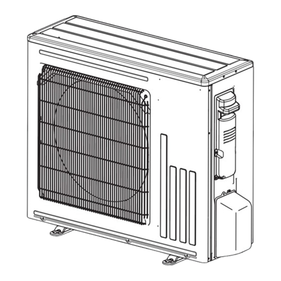
PART NAMES AND FUNCTIONS SUZ-SWM30VA SUZ-SHWM30VAH SUZ-SWM40VA2 SUZ-SWM40VA2-SC SUZ-SHWM40VAH SUZ-SHWM40VAH-SC SUZ-SWM60VA2 SUZ-SWM60VA2-SC Air inlet (Back and side) Piping Air outlet Drain outlet SUZ-SHWM60VAH SUZ-SHWM60VAH-SC SUZ-SWM80VA2 SUZ-SWM80VAH2 SUZ-SWM100VA SUZ-SWM100VAH Air inlet (Back and side) Piping Air outlet Drain outlet OCH796A... -
Page 6: Specification
SPECIFICATION MODEL NAME SUZ-SWM30VA SUZ-SHWM30VAH SUZ-SWM40VA2(-SC) SUZ-SHWM40VAH(-SC) SUZ-SWM60VA2(-SC) POWER SUPPLY(Phase, cycle, voltage) 1ø, 230V, 50Hz MAX. Current 13.5 Breaker capacity Outer casing Galvanized plate External finish Munsell 3Y 7.8/1.1 Refrigerant control Linear expansion valve Compressor Hermetic twin rotary Model SVB130FPBM1T SVB172FPKM1T Motor output... - Page 7 MODEL NAME SUZ-SHWM60VAH(-SC) SUZ-SWM80VA2 SUZ-SWM80VAH2 SUZ-SWM100VA SUZ-SWM100VAH POWER SUPPLY(Phase, cycle, voltage) 1ø, 230V, 50Hz MAX. Current 17.3 Breaker capacity * Outer casing Galvanized plate External finish Munsell 3Y 7.8/1.1 Refrigerant control Linear expansion valve Compressor Hermetic twin rotary Model SVB220FUAM2T Motor output Start type...
- Page 8 Cooling SUZ-SWM30VA SUZ-SHWM30VAH SUZ-SWM80VA(H)2 SUZ-SWM40VA2 SUZ-SHWM40VAH SUZ-SWM100VA(H) SUZ-SWM60VA2 SUZ-SHWM60VAH Minimum return water temperature due to the water quantity of system Minimum return water temperature due to the water quantity of system 21.0 21.0 Available range Available range 18.0 18.0 15.0 15.0 12.0 12.0...
- Page 9 Specifications and rated conditions of main electric parts SUZ-SWM30VA SUZ-SHWM30VAH Model SUZ-SWM40VA2 SUZ-SWM40VA2-SC Item SUZ-SHWM40VAH SUZ-SHWM40VAH-SC SUZ-SWM60VA2 SUZ-SWM60VA2-SC Smoothing capacitor (C61, C62, C63) 620 µF 420 V Diode module (DB61, DB65) 25 A 600 V (F701, F801, F901) T3.15AL250V Fuse (F61) 25 A 250 V (F62)
-
Page 10: Noise Criteria Curves
NOISE CRITERIA CURVES SUZ-S(H)WM30VA(H) SUZ-SWM40VA2(-SC) MUZ-RW35VGHZ-SC1 FUNCTION SPL(dB(A)) LINE FUNCTION SPL(dB(A)) LINE COOLING COOLING HEATING HEATING NC-70 NC-70 NC-60 NC-60 NC-50 NC-50 NC-40 NC-40 NC-30 NC-30 NC-20 NC-20 1000 2000 4000 8000 1000 2000 4000 8000 BAND CENTER FREQUENCIES, Hz BAND CENTER FREQUENCIES, Hz SUZ-SHWM40VAH(-SC) SUZ-SWM60VA2(-SC) - Page 11 SUZ-SHWM60VAH(-SC) SUZ-SWM80VA(H)2 FUNCTION SPL(dB(A)) LINE FUNCTION SPL(dB(A)) LINE COOLING COOLING HEATING HEATING NC-70 NC-70 NC-60 NC-60 NC-50 NC-50 NC-40 NC-40 NC-30 NC-30 NC-20 NC-20 1000 2000 4000 8000 1000 2000 4000 8000 BAND CENTER FREQUENCIES, Hz BAND CENTER FREQUENCIES, Hz SUZ-SWM100VA(H) FUNCTION SPL(dB(A)) LINE...
-
Page 12: Outlines And Dimensions
OUTLINES AND DIMENSIONS SUZ-SWM30VA Unit: mm SUZ-SHWM30VAH SUZ-SWM40VA2 SUZ-SWM40VA2-SC SUZ-SHWM40VAH SUZ-SHWM40VAH-SC SUZ-SWM60VA2 SUZ-SWM60VA2-SC OCH796A... - Page 13 SUZ-SHWM60VAH Unit: mm SUZ-SHWM60VAH-SC REQUIRED SPACE SUZ-SWM80VA2 SUZ-SWM80VAH2 SUZ-SWM100VA SUZ-SWM100VAH FLARED ø6.35 (1/4”) FLARED ø12.7 (1/2”) OCH796A...
-
Page 14: Wiring Diagram
WIRING DIAGRAM SUZ-SWM30VA SUZ-SWM40VA2 SUZ-SWM40VA2-SC SUZ-SWM60VA2 SUZ-SWM60VA2-SC SUZ-SHWM30VAH SUZ-SHWM40VAH SUZ-SHWM40VAH-SC OCH796A... - Page 15 SUZ-SHWM60VAH SUZ-SHWM60VAH-SC SUZ-SWM80VAH2 SUZ-SWM100VAH SUZ-SWM80VA2 SUZ-SWM100VA OCH796A...
-
Page 16: Refrigerant System Diagram
REFRIGERANT SYSTEM DIAGRAM Unit: mm SUZ-SWM30VA SUZ-SHWM30VAH SUZ-SWM40VA2 SUZ-SWM40VA2-SC SUZ-SHWM40VAH SUZ-SHWM40VAH-SC SUZ-SWM60VA2 SUZ-SWM60VA2-SC Refrigerant pipe ø12.7 4-way valve (with heat insulator) Strainer #100 Muffler Stop valve Muffler Defrost Outdoor thermistor Flared connection Discharge heat Ambient RT61 temperature exchanger temperature Capillary tube thermistor thermistor ø3.0×ø2.0×210 (x 2) - Page 17 MAX. REFRIGERANT PIPING LENGTH and MAX. HEIGHT DIFFERENCE Refrigerant piping: m Piping size O.D: mm Model Length A Max. Height difference B Liquid SUZ-SWM30VA SUZ-SHWM30VAH SUZ-SWM40VA2 SUZ-SWM40VA2-SC 2 – 26 12.7 6.35 SUZ-SHWM40VAH SUZ-SHWM40VAH-SC SUZ-SWM60VA2 SUZ-SWM60VA2-SC SUZ-SHWM60VAH SUZ-SHWM60VAH-SC SUZ-SWM80VA2 2 – 46 12.7 6.35 SUZ-SWM80VAH2...
- Page 18 Pumping down When relocating or disposing of the outdoor unit, pump down the system following From the main menu, select “Service” and change the setting as below. the procedure below so that no refrigerant is released into the atmosphere. You will be prompted to enter a password. THE FACTORY DEFAULT Turn OFF all the supply circuit (including Indoor unit, Heater, Outdoor unit etc.) PASSWORD is “0000”.
- Page 19 Fully close the stop valve on the gas pipe side of the outdoor unit when the pres- WARNING: sure gauge shows 0.05 to 0 MPa [Gauge] (approx. 0.5 to 0 kgf/cm 2 ) and quickly stop the outdoor unit. When the refrigeration circuit has a leak, DO NOT execute pump down •...
-
Page 20: Actuator Control
ACTUATOR CONTROL 8-1. OUTDOOR FAN MOTOR CONTROL The fan motor turns ON/OFF, interlocking with the compressor. [ON] The fan motor turns ON 5 seconds before the compressor starts up. [OFF] The fan motor turns OFF 15 seconds after the compressor has stopped running. 5 seconds 15 seconds Compressor... -
Page 21: Service Functions
SERVICE FUNCTIONS 9-1. CHANGE IN DEFROST SETTING Changing defrost finish temperature <JS> To change the defrost finish temperature, cut/solder the JS wire of the outdoor inverter P.C. board. (Refer to 10-6) Defrost finish temperature (°C) SUZ-SWM30VA SUZ-SHWM30VAH SUZ-SHWM60VAH SUZ-SWM40VA2 SUZ-SHWM60VAH-SC Jumper wire SUZ-SWM40VA2-SC SUZ-SWM80VA2... - Page 22 LEV opening 0–500 Pulses Primary current 0–50 DC bus voltage 180–370 Thermostat ON operating time 0–999 Minutes Outdoor unit-Control state Refer to "Detail Contents in Request Code" Compressor-Frequency control state Refer to "Detail Contents in Request Code" Outdoor unit-Microprocessor version information Example) Ver.9.00→"0900"...
- Page 23 Outdoor unit-EEPROM check information 4 alphanumeric characters Error history 1 (latest) Displays error history. (""-"" is displayed if no history Code is present) Error history 2 (second to last) Displays error history. (""-"" is displayed if no history Code is present) Error history 3 (third to latest) Displays error history.
- Page 24 9-3-2. Detail contents in request code [Operation state] (Request code :" 0") Relay output state Power currently Data display Display Compressor 4-way valve Solenoid valve supplied to compressor – – – – Relay output state Operation mode Operation mode Display Operation mode STOP COOL...
-
Page 25: Troubleshooting
TROUBLESHOOTING 10-1. CAUTIONS ON TROUBLESHOOTING 1. Before troubleshooting, check the following 1) Check the power supply voltage. 2) Check the indoor/outdoor connecting wire for miswiring. 2. Take care of the following during servicing 1) Before servicing the air to water heat pump, be sure to turn OFF the main unit first with the remote controller, and then after confirming the horizontal vane is closed, turn OFF the breaker and/or disconnect the power plug. - Page 26 10-2. TROUBLESHOOTING CHECK TABLE check Abnormal point/ Symptom LED indication Condition Remedy code Condition Outdoor unit 1-time blink eve- Outdoor power Overcurrent protection cut-out operates 3 consecutive • Reconnect connector of does not ry 2.5 seconds system times within 1 minute after the compressor gets started. compressor.
- Page 27 Abnormal point/ Symptom LED indication Condition Remedy Condition Outdoor unit 4-time blink Frequency drop by Temperature of discharge temperature thermistor exceeds • Check refrigerant circuit and refrig- operates. 2.5 seconds OFF discharge tempera- 111°C, compressor frequency lowers. erant amount. ture protection •...
- Page 28 10-4. TROUBLESHOOTING CRITERION OF MAIN PARTS Part name Check method and criterion Figure Defrost thermistor (RT61) Measure the resistance with a multimeter. Fin temperature Refer to 10-6. “Test point diagram and voltage”, 1. “Inverter P.C. thermistor (RT64) board”, for the chart of thermistor. Ambient temperature ther- mistor (RT65) Outdoor heat exchanger...
- Page 29 10-5. TROUBLESHOOTING FLOW A How to check inverter/compressor Disconnect the connector between the compressor and the power module (IC700). Check the voltage between terminals. See 10-5. “Check of open phase”. Are the voltages balanced? Replace the inverter P.C. board. Check the compressor. See 10-5.
- Page 30 D Check of compressor winding ● Disconnect the connector between the compressor and the power module (IC700), and measure the resistance between the compressor terminals. <<Measurement point>> At 3 points BLK-WHT * Measure the resistance between the lead wires at 3 points. BLK-RED WHT-RED <<Judgement>>...
- Page 31 G Check of outdoor thermistors Disconnect the connector of thermistor in the inverter P.C. board (see below table), and measure the resistance of thermistor. Replace the thermistor except RT64. Is the resistance of thermistor normal? When RT64 is abnormal, replace the (Refer to 12-6.1.) inverter P.C.
- Page 32 H Check of R.V. coil SUZ-S(H)WM30/40, SUZ-SWM60 * First of all, measure the resistance of R.V. coil to check if the coil is defective. Refer to 12-4. * In case CN721 is disconnected or R.V. coil is open, voltage is generated between the terminal pins of the connector although no signal is being transmitted to R.V.
- Page 33 I Check of outdoor fan motor Disconnect the connectors CN931 and CN932 from the inverter P.C. board. Check the connection between the connector CN931 and CN932. Is the resistance between each terminal of outdoor fan motor normal? (Refer to 12-4.) Disconnect CN932 from the inverter P.C.
- Page 34 J Check of power supply Disconnect the connector between the compressor and the power module (IC700). Turn ON power supply and Rectify indoor/outdoor press the emergency operation switch. connecting wire. Is there voltage 230 V AC Replace the indoor Does POWER lamp on the indoor between the indoor terminal electronic control P.C.
- Page 35 K Check of LEV Start Turn on power supply to the outdoor unit after checking Normal LEV coil is fixed to the LEV body securely. Is "click - click" sound heard? Or, do you feel vibration of the LEV coil with a hand? Disconnect the connector CN724 is there Replace the inverter P.C.
- Page 36 L Check of inverter P.C. board Check the outdoor fan motor. (Refer to 12-5. .) Is the fuse (F901) blown on the inverter P.C. board? Check the connection of the connectors (CN931, CN932) of the outdoor fan motor. If the connection is poor, make it correct. Operate the outdoor unit by starting EMERGENCY OPERATION.
- Page 37 M Check of the outdoor refrigerant circuit The operation has stopped to prevent the diesel explosion Has the operation stopped during pump down? caused by air trapped in the refrigerant circuit. Close the stop valve, and disconnect the power plug or turn the breaker OFF. CAUTION: Do not start the operation again to prevent hazards.
- Page 38 10-6. TEST POINT DIAGRAM AND VOLTAGE 1. Inverter P.C. board SUZ-SWM30VA SUZ-SHWM30VAH SUZ-SWM40VA2 SUZ-SWM40VA2-SC SUZ-SHWM40VAH SUZ-SHWM40VAH-SC SUZ-SWM60VA2 SUZ-SWM60VA2-SC Back side of unit Smoothing Smoothing Smoothing R.V.coil DB61 capacitor capacitor capacitor (CN721) 260 - 370 V DC (C61) (C62) (C63) 230 V AC 230 V AC Fuse (F801) Fuse (F701)
- Page 39 SUZ-SHWM60VAH SUZ-SHWM60VAH-SC SUZ-SWM80VA2 SUZ-SWM80VAH2 SUZ-SWM100VA SUZ-SWM100VAH Back side of unit Smoothing Smoothing Smoothing Output to drive Fuse (F880) Heater (CN601) Capacitor Capacitor Capacitor outdoor fan motor T3.15AL250V 230 V AC (CB1) (CB2) (CB3) (CN932) Fuse (F601) T3.15AL250V 230 V AC R.V.
-
Page 40: Disassembly Instructions
DISASSEMBLY INSTRUCTIONS <Detaching method of the terminal with locking mechanism> The terminal which has the locking mechanism can be detached as shown below. There are 2 types of the terminal with locking mechanism. The terminal without locking mechanism can be detached by pulling it out. Check the shape of the terminal before detaching. - Page 41 OPERATING PROCEDURE PHOTOS/FIGURES 2. Removing the inverter assembly and inverter P.C. Photo 3 board Screw of the heat sink Screw of the P.B. support support and the separator and the separator (1) Remove the cabinet and panels (refer to section 1). Screws of (2) Disconnect the lead wire to the reactor and the following the terminal block...
- Page 42 OPERATING PROCEDURE PHOTOS/FIGURES 3. Removing R. V. coil Photo 7 (1) Remove the cabinet and panels (refer to section 1). Screw of the (2) Disconnect the following connectors: R.V. coil <Inverter P.C. board> Discharge CN721 (R.V. coil) temperature (3) Remove the R.V. coil. thermistor Compressor protector...
- Page 43 OPERATING PROCEDURE PHOTOS/FIGURES 6. Removing the compressor and 4-way valve Photo 10 (1) Remove the cabinet and panels (refer to section 1). Discharge pipe Suction pipe (2) Remove the inverter assembly (refer to section 2). brazed part brazed part (3) Recover gas from the refrigerant circuit. NOTE: Recover gas from the pipes until the pressure gauge shows 0 kg/cm...
- Page 44 11-2. SUZ-SHWM60VAH SUZ-SHWM60VAH-SC SUZ-SWM80VA2 SUZ-SWM80VAH2 SUZ-SWM100VA SUZ-SWM100VAH NOTE: Turn OFF the power supply before disassembly. OPERATING PROCEDURE PHOTOS/FIGURES 1. Removing the cabinet Photo 1 Screws of the top panel (1) Remove the screws of the service panel. (2) Remove the screws of the top panel. (3) Remove the screw of the valve cover.
- Page 45 OPERATING PROCEDURE PHOTOS/FIGURES 2. Removing the inverter assembly and inverter P.C. Photo 3 board Screw of the heat sink Lead wires of the (1) Remove the cabinet and panels. (Refer to section 1.) support and the separator reactor (2) Disconnect the lead wire to the reactor and the following connectors: <Inverter P.C.
- Page 46 OPERATING PROCEDURE PHOTOS/FIGURES Photo 5 Connection procedure when attaching the inverter P.C. board (Photo 6, 7) 1. Attach the heat sink support to the P.C. board support. 2. Hook the lead wires of the compressor, the reactor and the P.C. board to each hooks on the heat sink support as shown Photo 7.
- Page 47 OPERATING PROCEDURE PHOTOS/FIGURES 3. Removing the discharge temperature thermistor, Photo 8 Outdoor heat exchanger defrost thermistor, outdoor heat exchanger tempera- temperature thermistor ture thermistor and ambient temperature thermistor (1) Remove the cabinet and panels. (Refer to section 1.) (2) Disconnect the lead wire to the reactor and the following connectors: <Inverter P.C.
- Page 48 OPERATING PROCEDURE PHOTOS/FIGURES 5. Removing the compressor and 4-way valve Photo 10 (1) Remove the top panel, cabinet and service panel. (Refer to Brazed part of Brazed part of section 1.) the discharge pipe the suction pipe (2) Remove the back panel. (Refer to section 1.) (3) Remove the inverter assembly.
- Page 49 HEAD OFFICE: TOKYO BUILDING, 2-7-3, MARUNOUCHI, CHIYODA-KU, TOKYO100-8310, JAPAN ©Copyright 2022 MITSUBISHI ELECTRIC CORPORATION Issued: Nov. 2022 No.OCH796 REVICED EDITION-A Published: Sep. 2022 No.OCH796 Specifications are subject to change without notice. Made in Japan...
Need help?
Do you have a question about the SUZ-SWM30VA TH Series and is the answer not in the manual?
Questions and answers