Table of Contents
Advertisement
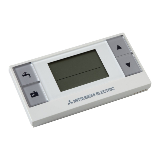
Wireless Remote Controller
and Receiver
PAR-WT50R-E
PAR-WR51R-E
Installation and Setting Manual
For safe and correct use, please read this manual thoroughly before installing the PAR-WT50R-E and
PAR-WR51R-E devices.
Installations- und Konfigurationsanleitung
Lesen Sie sich zur sicheren und korrekten Verwendung diese Anleitung bitte sorgfältig durch, bevor Sie die
Geräte PAR-WT50R-E und PAR-WR51R-E installieren.
Manuel d'installation et de configuration
Pour garantir une utilisation sûre et appropriée, lisez attentivement le présent mode d'emploi avant d'installer
les dispositifs PAR-WT50R-E et PAR-WR51R-E.
Handleiding voor installeren en instellen
Voor een veilig en juist gebruik moet u deze handleiding goed doorlezen alvorens de PAR-WT50R-E en
PAR-WR51R-E apparaten te installeren.
Manual de instalación y configuración
Para un uso correcto y seguro de los dispositivos PAR-WT50R-E y PAR-WR51R-E, lea este manual antes de
su instalación.
Manuale di installazione e impostazione
Per un uso corretto e sicuro, leggere attentamente il presente manuale prima di installare i dispositivi
PAR-WT50R-E e PAR-WR51R-E.
Manual de Instalação e Definição
Para uma utilização segura e correcta, é favor ler cuidadosamente este manual antes de instalar os dispositi-
vos PAR-WT50R-E e PAR-WR51R-E.
Installations- og indstillingsvejledning
Læs venligst denne vejledning grundigt inden installation af enhederne PAR-WT50R-E og PAR-WR51R-E af
hensyn til sikker og korrekt brug.
Installations- och Inställningsmanual
För säker och korrekt användning, var god läs denna manual noggrant innan du installerar PAR-WT50R-E-
och PAR-WR51R-E-enheterna.
Installasjons- og konfigurasjonsanvisning
Les denne bruksanvisningen nøye før du installerer PAR-WT50R-E og PAR-WR51R-E, for å sikre trygg og
riktig bruk.
Asennus- ja asetusopas
Turvallisen ja asianmukaisen käytön varmistamiseksi lue tämä opas huolellisesti ennen PAR-WT50R-E- ja
PAR-WR51R-E-laitteiden asennusta.
FOR INSTALLER
FÜR DEN INSTALLATEUR
POUR LES INSTALLATEURS
VOOR DE INSTALLATEUR
PARA EL INSTALADOR
PER L'ADDETTO ALL'INSTALLAZIONE
PARA O INSTALADOR
TIL INSTALLATØR
FÖR INSTALLATÖREN
FOR INSTALLATØREN
ASENTAJALLE
English (EN)
Deutsch (DE)
Français (FR)
Nederlands (NL)
Español (ES)
Italiano (IT)
Português (PT)
Dansk (DA)
Svenska (SV)
Norsk (NO)
Suomi (FI)
Advertisement
Table of Contents

Subscribe to Our Youtube Channel
Related Manuals for Mitsubishi PAR-WT50R-E


Summary of Contents for Mitsubishi PAR-WT50R-E
-
Page 1: Wireless Remote Controller
PAR-WR51R-E apparaten te installeren. Manual de instalación y configuración PARA EL INSTALADOR Español (ES) Para un uso correcto y seguro de los dispositivos PAR-WT50R-E y PAR-WR51R-E, lea este manual antes de su instalación. Manuale di installazione e impostazione PER L'ADDETTO ALL'INSTALLAZIONE... -
Page 2: Table Of Contents
This manual explains installation of the PAR-WR51R-E wireless receiver and the PAR-WT50R-E wireless remote controller, and settings of these devices. Before in- stalling the devices, read this manual thoroughly. After reading, be sure to hand this manual to the user. - Page 3 Annex IV, and/or to the directive 2006/66/EC Article 20 Information for end-users and Annex II. Your MITSUBISHI ELECTRIC product is designed and manufactured with high quality materi- als and components which can be recycled and/or reused. This symbol means that electrical and electronic equipment, batteries and accumulators, at their end-of-life, should be disposed of separately from your household waste.
-
Page 4: Accessories And Installation Tool
Following is the summary of the procedure for installing and setting the wireless system. 1. Devices and manuals required to set and install the wireless system PAR-WT50R-E wireless remote controller PAR-WR51R-E wireless receiver ATW wireless system installation and setting manual (this manual) -
Page 5: Installing Wireless Receiver
Test wireless communication between the wireless remote controller and the wireless receiver. (See “6.4 Communication Test” in “6. Setting wireless remote controllers” in this manual.) Position the wireless remote controller in an appropriate place. (See "4. Before Operation" in OM.) To set the wireless remote controller as a room sensor that monitors room temperature, see "Main remote controller Options"... - Page 6 Remove the screw and pull the control and electrical box so that the control and electrical box is swung toward you from left. Control and electrical box Control and electrical box Screws (2 positions) Screw (1 position) Run the receiver's cable into the cylinder unit Receiver’s cable through the inlet as shown on the figure.
- Page 7 Connect the cable connector to the CNRF terminal on the control board. Switch ON SW1-8. CNRF Remove excessive slack on the cable , then secure the cable with a cable fastener and 2 ca- ble straps on the upper side and center on the back of control and electrical box. Back view Cable Control and...
- Page 8 Place the control and electrical box back in the original position and reinstall the 3 screws. Check the maximum reach of the cable and install the bracket on the wall with screws. Do not excessively pull the cable when checking the maximum reach. <Notice>...
-
Page 9: Connecting To Hydrobox
4.2 Connecting to Hydrobox * Before installation, be sure to turn off the main power supply. Remove the two screws that hold the front panel, and remove the panel. Front panel Screws (2 positions) Route the receiver's cable into the hy- drobox through the leftmost inlet at the bottom of the unit. - Page 10 Connect the cable connector to CNRF on the control board. Switch ON SW1-8. CNRF Check the maximum reach of the cable and install the bracket with screws. Do not excessively pull the cable when measuring the maximum reach. <Notice> ● Do not overtighten the screws. ►The bracket may deform or break.
-
Page 11: Pairing Process
Place the wireless receiver on the fixed bracket. Hook the holes on the back of the wireless re- ceiver onto the projections on the bracket, and fix the wireless receiver. <Notice> ● Do not place the wireless receiver inside the hydrobox. ►Both the wireless receiver and its wire may break due to heat inside the indoor unit. - Page 12 Press button to set the mode number to “1” and press button. When button is pressed in the middle of setting, the screen returns to the previous indication. When appears on the display, do not perform pairing. The power may be turned off in the middle of pairing, which may lose the pairing information.
-
Page 13: Setting Wireless Remote Controllers
When " " appears on the remote controller <Pairing is unsuccessful> and green LED on the wireless receiver blinks , correctly repeat the same process from step 5. Even if the pairing process failed, the wireless receiver stays in the pairing mode for 5 minutes unless cancelled. -
Page 14: Viewing Address Number
Confirm setting by pressing button. The display stops blinking and lights steadily. When button is pressed in the middle of set- ting, the screen returns to the previous indication. Mode Initial Names Functions settings Pairing address dis- To view the own pairing address of the wireless play remote controller. -
Page 15: Communication Test
6.4. Communication Test (Mode No. 3) Set the mode no. to “3”. Communication test is performed between the wireless remote controller and the wireless re- ceiver. When the display shows " ", this indicates that the communication between the remote controller and the receiver is established. -
Page 16: Automatic Zone No. Display
When the indoor unit is operating, the room tem- perature display shows the actual room tempera- ture (18°C) below and the set temperature (20°C) above as shown in the figure to the right. The meas- urable temperature range is from 0°C to 40°C. If the measured room temperature is out of 0°C to 40°C range, the room temperature display blinks. -
Page 17: Wireless Receiver Operation
7. Wireless Receiver Operation The wireless receiver is powered by indoor unit. It communicates with the wireless remote controller(s), and transmits to the indoor unit the operation status and commands received from the wireless remote controlle(s). The wireless receiver has two modes available: pairing mode and pairing reset mode. -
Page 18: Turning On Power
7.2. Turning on Power Power ON When the wireless receiver is powered by in- door unit after installation, green and orange LED blink for 3 seconds. 7.3. Wireless Receiver Functions Not paired (1) Normal mode When the wireless receiver is paired with a wireless remote controller, green comes on. -
Page 19: Faq
8. FA Q Questions Answers How many wireless Up to 8 controllers. remote controllers are allowed to be paired? What should be noted • The same address cannot be assigned to multiple remote about Pairing? controllers • If the same address is assigned to multiple controllers, the address can be assigned to only the last paired remote con- troller. -
Page 20: Specifications
Supplementary information Product fiche of temperature control (a) Supplier’s name: MITSUBISHI ELECTRIC CORPORATION (b) Supplier’s model identifier: PAR-WT50R-E and PAR-WR51R-E (c) The class of the temperature control: (d) The contribution of the temperature control to seasonal space heating energy efficiency: 4%... - Page 21 Please be sure to put the contact address/telephone number on this manual before handing it to the customer. HEAD OFFICE: TOKYO BLDG., 2-7-3, MARUNOUCHI, CHIYODA-KU, TOKYO 100-8310, JAPAN Authorized representative in EU: MITSUBISHI ELECTRIC EUROPE B.V. HARMAN HOUSE, 1 GEORGE STREET, UXBRIDGE, MIDDLESEX UB8 1QQ, U.K. BH79R517K04...
Need help?
Do you have a question about the PAR-WT50R-E and is the answer not in the manual?
Questions and answers