Moxa Technologies awk-5222 Quick Installation Manual
Hide thumbs
Also See for awk-5222:
- User manual (100 pages) ,
- Quick installation manual (15 pages) ,
- User manual (86 pages)

Related Manuals for Moxa Technologies awk-5222


Summary of Contents for Moxa Technologies awk-5222
-
Page 1: Quick Installation Guide
AWK-5222 Quick Installation Guide Moxa AirWorks Third Edition, June 2014 2014 Moxa Inc. All rights reserved. P/N: 1802052220012... -
Page 2: Package Checklist
Step 1: Select the power source The AWK-5222 can be powered by a DC power input or PoE (Power over Ethernet). The AWK-5222 will use whichever power source you choose. Step 2: Connect the AWK-5222 to a notebook or PC... - Page 3 Step 5: Select the operation mode for the AWK-5222 By default, the AWK-5222’s operation mode is set to Wireless Redundancy. You can change the setting in Wireless Settings Operation mode if you would like to use the Wireless Bridge or AP-Client mode.
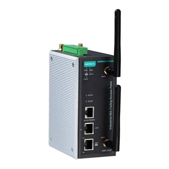
- Page 4 Panel Layout of the AWK-5222 1. Grounding screw 2. Terminal block for PWR1, PWR2, relay, DI1, and DI2 3. Reset button 4. Heat dissipation orifices 5. AUX1 and AUX2 antenna ports 6. System LEDs: PWR1, PWR2, PoE, FAULT, and STATE LEDs 7.
-
Page 5: Din-Rail Mounting
DIN-Rail Mounting The aluminum DIN-Rail attachment plate should be fixed to the back panel of the AWK-5222 when you take it out of the box. If you need to reattach the DIN-Rail attachment plate to the AWK-5222, make sure the stiff metal spring is situated towards the top, as shown in the figures below. -
Page 6: Wiring Requirements
Once the screws are fixed into the wall, insert the four screw heads through the large opening of the keyhole-shaped apertures, and then slide the AWK-5222 downwards, as indicated to the right. Tighten the four screws for added stability. Wiring Requirements... -
Page 7: Wiring The Redundant Power Inputs
Wiring the Redundant Power Inputs The top two pairs of contacts of the 10-contact terminal block connector on the AWK-5222’s top panel are used for the AWK-5222’s two DC inputs. Top and front views of the terminal block connector is shown here. -
Page 8: Wiring The Relay Contact
Wiring the Relay Contact The AWK-5222 has one relay output, which consists of the two contacts of the terminal block on the AWK-5222’s top panel. Refer to the previous section for detailed instructions on how to connect the wires to the terminal block connector, and how to attach the terminal block connector to the terminal block receptor. -
Page 9: Communication Connections
The AWK-5222 has one RS-232 (8-pin RJ45) console port located on the front panel. Use either an RJ45-to-DB9 or RJ45-to-DB25 cable to connect the Moxa AWK-5222’s console port to your PC’s COM port. You may then use a console terminal program to access the AWK-5222 for console configuration. -
Page 10: Led Indicators
LED Indicators The front panel of the Moxa AWK-5222 contains several LED indicators. The function of each LED is described in the table below. Color State Description Front Panel LED Indicators (System) Power is being supplied from power input 1. -
Page 11: Specifications
Specifications WLAN Standards IEEE 802.11a/g/b for Wireless LAN IEEE 802.11i for Wireless Security IEEE 802.3u for 10/100BaseT(X) IEEE 802.3af for Power-over-Ethernet IEEE 802.1D for Spanning Tree Protocol IEEE 802.1w for Rapid STP Spread Spectrum and DSSS with DBPSK, DQPSK, CCK Modulation OFDM with BPSK, QPSK, 16QAM, 64QAM Operating Channels... - Page 12 5 years For details see http://www.moxa.com/warranty ATTENTION The AWK-5222 is NOT a portable mobile device and should be located at least 20 cm away from the human body. The AWK-5222 is NOT designed for the general public. To deploy AWK-5222s and establish a wireless network safely, a well-trained technician is required for installation.
- Page 13 ATTENTION Use the antennas correctly: Two dual-band 2.4 GHz & 5 GHz antennas, are included with the product. Either antenna can be installed in MAIN1 or MAIN2. If you want to use a single band antenna, please use 2.4 GHz antennas for IEEE 802.11b/g mode and 5 GHz antennas for IEEE 802.11a mode.
Need help?
Do you have a question about the awk-5222 and is the answer not in the manual?
Questions and answers