Table of Contents
Advertisement
Montageanleitung
Mounting Instructions
Instructions de montage
Istruzioni di montaggio
Instrucciones de montaje
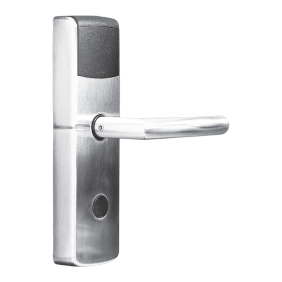
Dialock Türterminal DTSH, DTSH FH
Dialock Door Terminal DTSH, DTSH FH
Dialock Terminal de Porte DTSH, DTSH FH
Dialock Terminale Porta DTSH, DTSH FH
Dialock Terminal de Puerta DTSH, DTSH FH
DE
EN
FR
IT
ES
Advertisement
Table of Contents

Subscribe to Our Youtube Channel
Related Manuals for Hafele dialock DTSH


Summary of Contents for Hafele dialock DTSH
- Page 1 Montageanleitung Mounting Instructions Instructions de montage Istruzioni di montaggio Instrucciones de montaje Dialock Türterminal DTSH, DTSH FH Dialock Door Terminal DTSH, DTSH FH Dialock Terminal de Porte DTSH, DTSH FH Dialock Terminale Porta DTSH, DTSH FH Dialock Terminal de Puerta DTSH, DTSH FH...
-
Page 2: Table Of Contents
Installation Instructions Contents Scope of delivery ..................39 Accessories (not included in the scope of delivery) ......40 DTSH Application areas ...............42 DTSH FH application areas ..............42 Features ....................42 Installation instructions .................43 Start-up ....................63 Short instructions .................65 Operation ....................66 Battery change ..................66 Emergency opening ................68 FAQ.......................69 Maintenance and cleaning instructions ..........69... - Page 3 Installation Instructions Dialock Door Terminals DTSH, DTSH FH - Status: 07.2008 - 732.29.134...
-
Page 4: Scope Of Delivery
Installation Instructions Always follow the instructions in the "Start-up and maintenance" guide when starting up (assigning keys)! Scope of delivery 1 External module 1 Internal module Small parts bag with profile cylinder cover (break-open seal) 1 Promaseal strip (DTSH FH only) Fig. -
Page 5: Accessories (Not Included In The Scope Of Delivery)
Installation Instructions Accessories (not included in the scope of delivery) Accessories (not incl. in the scope of delivery) Cat. No. Black plastic spacer plate 917.90.492 Stainless steel spacer plate for DTSH FH 917.90.216 Profile cylinder cover (break-open seal), plastic, black 25 pieces 917.90.483 Optional:... - Page 6 Installation Instructions Accessories (not incl. in the scope of delivery) Cat. No. Mounting sets for DTSH No. Door thickness Consisting of 37 – 47 mm 1 inner square spindle L=100mm 917.90.242 4 countersunk head screws DIN 965 M4x30 für DTSH FH 917.90.121 47 –...
-
Page 7: Dtsh Application Areas
Installation Instructions DTSH Application areas The Dialock DTSH door terminal is an electronic door fitting for use in hotels. It is mounted to internal doors with mortise locks in accordance with DIN 18 251* and can also be easily retrofitted to the door leaf. The use of a single profile cylinder is recommended for emergency openings. -
Page 8: Installation Instructions
Fig. 4 The length of the following Dialock DTSH door terminal components depends on the thickness of the door leaf. They must therefore be selected accordingly. Mounting set consisting of: Fixing screws and inner square spindle (for scope of delivery see page 39). - Page 9 Installation Instructions The black plastic profile cylinder cover is also a break-open seal and must not be fitted until start-up has taken place. Do not bring media (keys) into the reading area during installation if the batteries have been inserted! Dialock Door Terminals DTSH, DTSH FH - Status: 07.2008 - 732.29.134...
- Page 10 Installation Instructions Tools Tools Cat. No. Locking ring pliers (for fitting locking 917.90.900 ring to inner square spindle) SW3 T-handle for 006.32.013 grub screws of lever handle aperture part and removing the inner hood DTSH DIN drilling jig 917.90.005 Router cutter for breakthrough to lock Ø...
- Page 11 Page 54 Adjust external module for right-pointed/left-pointed door Page 56 handle Secure inner square spindle Page 57 Mount external module of Dialock DTSH door terminal Page 58 Mount internal module Page 60 With emergency opening log, protect connecting cable during the drilling procedure as shown in the illustration.
- Page 12 Installation Instructions Insert mortise lock Risk of the cable being crushed by mortise lock with emergency opening log! Insert mortise lock. cable incorrect Fig. 9 Fig. 10 correct Hooded screw cable Fig. 11 Fig. 12 Screw in the mortise lock. With mortise lock with emergency opening log, the mortise lock con- necting cable must be fixed in position as shown in fig.
- Page 13 Installation Instructions B. Drill holes for fixing screws and connecting cable In order to obtain a neat drill hole, the through holes should first be part drilled from one side of the door to the middle of the door leaf and then drilled through from the other side of the door.
- Page 14 Installation Instructions Only for emergency opening log Depth cutting to lock pocket Ø 32 mm Centring hole for router cutter with centring pin Space for coupling Inside of Outside of door door Section: Fig. 14 Depth cutting only needed for Fig.
- Page 15 Installation Instructions Use drilling jig The drilling jig consists of parts A, B and C. The drilling template must be prepared in combinations A-B and A-C depending on the drill hole. Select drilling jig with part A-B and A-C for the individual drill holes: Insert centring pins for drilling jig (part A) through the square spindle Centring...
- Page 16 Installation Instructions Drill holes on inside of door Fig. 18 Fig. 19 Drill the fixing holes at both sides Drill 13 mm hole at both sides for as far as the middle of the door leaf cable connection. using the 8 mm drill bit. Cut out the coupling area.
- Page 17 Installation Instructions Only required with emergency opening log! Drill through to the middle of the door leaf from both sides using the 8 mm drill bit to connect the emergency opening log. (Centring hole for 32 mm router cutter) This procedure can destroy the connecting cable for emergency opening log.
- Page 18 Installation Instructions C. Remove mortise lock, clean and re-insert Remove mortise lock. Outside of door is already drilled and cut. Before continuing, remove debris and clean lock pocket. Fig. 24 Door leaf Connector With emergency Depth cutting opening log, lead con- Connection cable necting cable into the inside of the lock pock-...
- Page 19 Installation Instructions D. Insert single profile cylinder Failure to follow these instructions will destroy the single profile cylinder and the lock. Do not use force. Only use one single profile cylinder with the correct length! (See fig. 26) External fitting Door leaf Single profile cylinder Forend screw...
- Page 20 Installation Instructions The follower must be in the correct position! Otherwise the switching mechanism will be damaged. The follower only needs to be adjusted with a mortise lock with emer- gency opening log. Adjust follower of single profile cylinder as shown in the illustration on the right.
- Page 21 Installation Instructions E. Adjust external module for right-pointed/left-pointed door handle The Dialock DTSH FH door terminal is supplied already set up and must not be modified. Place lever handle aperture part onto outer square spindle of external module so that the direction of movement matches the application.
- Page 22 Installation Instructions F. Secure inner square spindle 2 Arrow marking 1 "Lug" Fig. 32 Fig. 33 Inner square spindle with groove Rotate marking (lug) (1) of coupling part in direction V (2). Before inserting the inner square spindle into the cou- pling part, align it so that the groove of inner square spindle and the grub screw of the lever handle aperture part are pointing in the same direction.
- Page 23 Installation Instructions G. Mount external module of Dialock DTSH door terminal The following prerequisites must be complied with: Holes drilled as per drilling plan Door lock and locking cylinder inserted If the distance between the surface of the door leaf (outer) and the lock case is less than 6 mm a spacer plate must be used, otherwise the external module will be touching the lock cover.
- Page 24 Installation Instructions Do not trap cable! Vertically align external module so that the guide pins of the external module engage in the holes. Slide external module towards door leaf until it is lying flat against it. (Fig. 40) Fig. 40 If the external module does not lie flat against the door: Check drill holes and remove wood debris if...
- Page 25 Installation Instructions H. Mount internal module Risk of crushing! Pay attention to cable routing! Line 13 mm DTSH FH cable hole with Proma- seal strips, shorten to door leaf thickness and glue in parallel to cable. Lead connector of connecting cable through opening in internal module fixing plate, fig.
- Page 26 Installation Instructions Pay attention to position of "Do not disturb" rotary knob! The rotary knob must be vertical during installation and the grooved side of the square spindle at the internal module must point in the direction of the forend. Fig.
- Page 27 Installation Instructions And tighten screw. Always use the original grub screws in the provided small parts bag. Remove other grub screws from lever handle aperture part if necessary. Always use the provided lever handle with the DTSH FH. Fig. 48 The small parts bag for the FH version does not contain any grub screws.
-
Page 28: Start-Up
Installation Instructions Start-up The Dialock DTSH door terminal is supplied in so-called "simple mode" for standalone operation (SA). This is the only operating mode that is described in these instructions. Details about the use of the DTSH in con- junction with software applications (Dialock HOTEL, PERSONNEL, hotel management systems etc.) can be found in the relevant documentation. - Page 29 When the key has been trained successfully, the LED will be perma- nently blue and an acoustic signal will be heard. The Dialock DTSH door terminal then goes into normal operating mode. If persistent errors occur: Notify the service location.
-
Page 30: Short Instructions
If a user key has been lost and you wish to cancel its locking authorisa- tions, all user keys must first be deleted at the Dialock DTSH door termi- nal. Access rights must then be re-allocated to all user keys with locking authorisations. -
Page 31: Operation
The blue LED flashes and the red LED goes off. The Dialock DTSH door terminal is ready for opening for approx. 3 sec- onds. The door can be opened by pushing the lever handle. - Page 32 The following steps are required to change the batteries: The batteries are located in the internal module of the Dialock DTSH door terminal. Loosen the grub screw of lever handle aperture part at the inside of the door using an Allen key.
-
Page 33: Emergency Opening
Push in break-open seal (profile cylinder cover) with a small screw- driver and remove. Open Dialock DTSH door terminal using an emergency opening key. Insert new break-open seal. The single profile cylinder is only used for opening, not for locking. -
Page 34: Maintenance And Cleaning Instructions
If a user key has been lost and you wish to cancel its locking authorisa- tions, all user keys must first be deleted at the Dialock DTSH door termi- nal. Access rights must then be re-allocated to all user keys with locking authorisation.
Need help?
Do you have a question about the dialock DTSH and is the answer not in the manual?
Questions and answers