MasterCool MCP59 Installation And Operating Manual
Hide thumbs
Also See for MCP59:
- Installation and operating manual (15 pages) ,
- Installation and operating manual (28 pages) ,
- Installation & operating manual (28 pages)
Table of Contents
Advertisement
Available languages
Available languages
Advertisement
Chapters
Table of Contents

Related Manuals for MasterCool MCP59


Summary of Contents for MasterCool MCP59
- Page 1 Keep this document for future reference. Guarde este documetno para consultarlo en el futuro. SERIAL NUMBER / NÚMERO DE SÉRIE: ___________________________________ DATE OF PURCHASE / FECHA DE COMPRA: ___________________________________ 72908 4/2015 Printed in USA ...
-
Page 2: Table Of Contents
Do not use an adapter to convert the three pin connector for use in an ungrounded 2 prong outlet. DO NOT use with a solid state speed control device. Violation of this could cause fire or electrical shock. Do not alter or modify this cooler. Repairs or replacement of electrical components should only be carried out by qualified electricians. Do not allow children to install, service, or operate the cooler. This fan cannot be used as an exhaust fan in a kitchen, and must be a minimum of 3 feet from open flame. Table of Contents Safety Instructions .............................. 2 Note About Evaporative Coolers .......................... 3 Features of the MasterCool® MCP59 Window Cooler .................... 3 Installation Procedures ............................... 4 Cooler Assembly ............................... 4 Installation in Window .............................. 5 Installation in Wall .............................. 5 Water Connection, Water Pump and Lines, Overflow Drain, Water Level ............ 6 Electrical System & Specifications .......................... 7 Plug‐in Thermostat usage ............................ 7 Optional Purge Pump ............................. 7 Operating Instructions .............................. 8 User Servicing Instructions ............................ 9 Annual Maintenance .............................. 9 ... -
Page 3: Note About Evaporative Coolers
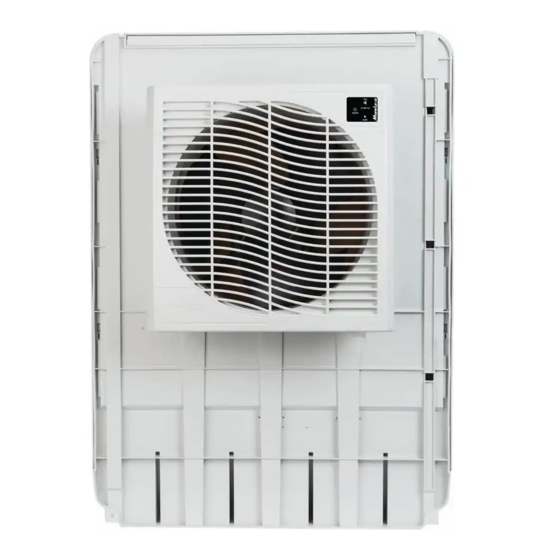
NOTE: Evaporative coolers WILL NOT work in a Closed Room should not be on the windward side on the house. Water bleed or purge: Evaporative Coolers require a continuous supply of water to keep the media saturated for maximum cooling. Water pumped into the cooler must be removed from the unit to ensure mineral and bacteria build‐up do not occur. This can occur with a gravity‐fed steady bleed off stream or a timed purge system via a pump. A purge pump kit (MCP44‐PPK) is available at www.championcooler.com or at 800.643.8341 to order. CAUTION: Water expelled from the cooler must be routed away from any areas that could do damage to foundations or other vulnerable areas. NOTE: Drawings in this manual are for illustrative purposes only and may reflect slight differences depending on design level and configuration. Features of the MasterCool® MCP59 Window Cooler WATER DISTRIBUTION TRAY FAN HOUSING WITH REMOVABLE FASCIA FAN MOTOR ... -
Page 4: Installation Procedures
NOTE: BEFORE INSTALLING UNIT, TAKE A MOMENT TO RECORD THE SERIAL NUMBER AND WRITE IT ON THE . MANUAL COVER IN THE SPACE PROVIDED INSTALLATION PROCEDURES WARNING: Do not connect electrical power to the unit until the installation is completed. The MasterCool MCP59 cooler can be installed in a sash‐style or a slider‐ style window. Alternatively, this unit is approved for in‐wall installations. In all installations, the following clearances are required: Width: 22”; Height: 22” 4” clearance above the exterior cabinet is needed for maintenance. NOTE: Ensure the location selected for installing the unit is strong enough to support the unit and will accept the mounting hardware. The operating weight of the cooler is 93 pounds. NOTE: A minimum of two people is required for installation. Parts Included: Cooler Unit Mounting brackets (4) Accordion spacers (2) Hardware kit Tools & Materials Required: Drill (power or cordless) Assorted drill bits (for drilling pilot holes for mounting hardware) Adjustable Wrench Phillips Head Screwdriver Silicone or all‐weather caulk for sealing infill panel to window frame Length of ¼” copper or plastic tubing Sillcock valve Bubble level Spacer material (as required) ... -
Page 5: Installation In Window
Installation in Window 1. Remove screen ( as needed) and make sure window is opened to its maximum height. From the exterior of the window, slide the fan WINDOW assembly section into the window. Have the 4” MINIMUM person on the interior adjust the exact placement of the unit for aesthetics and OPTIONAL MOUNTING 2 PLACES - correct lengths of the two accordion spacers MINIMUM 14” APART (included). Note: After identifying the position for SCREW WINDOW installation, place a bubble level on top of the WINDOW SILL unit and make adjustments to ensure the unit SCREWS WINDOW SILL BRACKET will be level when installation is complete. It is SCREW WINDOW SILL recommended to verify unit is level at various points during installation. SPACER TO ENSURE FLUSH/SQUARE INSTALLATION (NOT SUPPLIED) - Page 6 SHUT OFF VALVE Water Connection PLASTIC OR NOTE: A standard sillcock with water valve attached (locally available) will COPPER LINE TO COOLER be required to connect the water supply to the cooler. 1. Steady water supply is required for operation of the cooler. If taking water from an external water faucet, install a sillcock and shutoff valve. 2. Install plastic or copper line to sillcock and connect it to the float valve. SILLCOCK STD. HOSE CONNECTION Water Pump and Lines FLOAT VALVE A self‐contained water pump continuously WATER LINE circulates water through the water distribution ATTACH POINT system and over the media. . The pump and water lines are shipped unconnected MAIN ...
-
Page 7: Plug-In Thermostat Usage
Electrical System The electrical system does not require general maintenance. The following wiring diagram is supplied for reference only. (OPTIONAL OWNER-INSTALLED PURGE PUMP) ELECTRICAL SPECIFICATIONS OF MCP59 COOLERS MCP59 Fan Motor: 120 V; 3.34 Amps Main Pump: 120 V; 0 .9 Amps If Optional PURGE PUMP is installed Additional 0.9 Amps Plug‐In Thermostat Usage The MCP59 can be controlled by a plug‐in programmable thermostat. These thermostats are locally available, and enable precise timing and temperature control via an electronic thermostat that plugs into a 110 volt outlet. To use such a device with the MCP59, follow the instructions for the specific thermostat and plug the cooler into the outlet on the thermostat. Optional Purge Pump In addition to the standard water pump to recirculate water from the reservoir, a purge pump can be installed to evacuate the contents of the reservoir every 6 hours. This helps retard bacterial growth and mineral buildup on the media, extending its life. It also maintains fresher air in the home. The use of the purge pump is actually more economical to use than a continual bleed line. The purge pump kit (P/N MCP44‐PPK) for this unit may be purchased online at www.championcooler.com or by phone at 1.800.643.8341. Purge Pump Discharge NOTE: The water ejected at the time of purging will be expelled at a high rate of speed, and must be routed away from the foundation of the home or other areas where rushing water could do damage. 1. Attach a standard water hose to the overflow drain to direct the water away from the house. NOTE: This water is not potable, but can be used for watering vegetable or flower gardens. 7 ... -
Page 8: Operating Instructions
OPERATING INSTRUCTIONS The MCP59 has an electronic touch control panel in the upper right hand corner. Before turning unit on, ensure unit is plugged in, water supply to pump is on, and there is correct ventilation, as shown on page 3 of this Fan Speeds: manual. HI MED LO Power Note: These units may be controlled using the 3 buttons on the front panel of the cooler or Water Pump with the remote control. On/Off PUMP On/Off This button initiates power to the unit. When Indicator first plugged, pressing ON/OFF will start the Lights unit in the default setting (pump ON and Fan on HIGH). After its initial use, the last operating settings (for fan and pump) will be reinstated when the unit is turned on again. Pressing this button when the unit is already running will turn both fan and pump off. After A Power Failure: Once power is restored, the unit will restart in the same settings as before power was lost. Pump This button toggles the pump on and off. When the LED is lit, the pump is running. The pump must be on while operating the fan for the unit to operate as an evaporative cooler, though the unit can be used in fan mode without the pump, if desired. ... -
Page 9: User Servicing Instructions
USER SERVICING INSTRUCTIONS Maintenance on evaporative coolers is minimal, but very important to the proper operation and effectiveness of your cooler. Periodic inspection of the cooler’s interior will reduce the potential for substandard cooling due to insufficient or uneven water distribution. NOTE: For general maintenance purposes, the unit may be rapidly drained of water by removing the overflow fitting from the bottom of the unit. This is not adequate draining for winterization (see procedures under Winterization section.) Annual Maintenance (May be Needed More Often in Areas with Hard Water) Cleaning WARNING: Disconnect from electrical power and turn unit off during all maintenance. Turn water supply off before removing back for cleaning or maintenance. 1. Remove the back media guard (as shown below). LOCATE MEDIA PEGS AND REMOVE. 2. Inspect pads in place. Remove media pads from back USING PLIERS, guard by unscrewing the media peg clips. OR PULL CLIPS PULL PLUGS OFF PEGS FROM Be careful not to chip or damage the media while OUT FROM THE THE INTERIOR. EXTERIOR. removing. Visually inspect both sides of media pads. Look for blockage, mineral build‐up or mildew growth, breakage or other anomalies. ... - Page 10 7. Rinse thoroughly after using any cleaning solutions on the interior or exterior of the unit. Water System Pump: 1. The water pump is a self‐contained unit that should require no maintenance other than ensuring that no debris or corrosion interferes with free movement of the parts. 2. Ensure hose connection to pump is in good condition. Water Float: 1. The float level is factory set for optimum performance, however moderate adjustments can be made by bending the float arm for a different water level. 2. The maximum recommended water level is approximately two inches (the height of the overflow orifice.) Water Distributor 1. Inspect the water distribution section to ensure all orifices are clear. 2. Verify the hose connections are in good order and no kinks or tears are present. Water Drain Overflow 1. Unscrew the drain overflow pipe and check the condition of the gasket at the bottom of the fixture. When reinstalling, ensure the standpipe fixture is secure and there is no leakage after the reservoir is filled. NOTE: If during usage of the cooler you start noticing low saturation of pads and insufficient cooling, or leakage from the cooler, check the O‐ring at the base of the standpipe. This is the most likely cause of leakage on this unit. Optional Water Purge Pump (if installed) 1. If a purge pump (MCP44‐PPK) has been installed on the MCP59, check that the purge pump and strainer are corrosion‐free with freely moving parts. Media Pad Replacement 1. When the media pads have become encased with mineral buildup, broken or damaged, replace them with Genuine Munter’s replacement pads, model MCP44‐PAD. You may purchase them online at www.championcooler.com or by calling 1.800.643.8341. 10 ...
-
Page 11: Winterization
Winterization The MCP59 cooler is durable enough to be left installed during the winter, though a few precautions must be taken to ensure no water freezes in the unit or lines. If the temperatures in your area drop well below freezing it may be wise to remove the water supply line from the outside faucet. Draining MCP59: 1. Turn the water supply to the cooler off. 2. Turn off and unplug cooler. Remove 4 screws securing the back media guard and access interior of unit. 3. Soak up any remaining water and ensure all water is drained from both the water pump and the purge pump. 4. Disconnect and drain the water hoses and water distributor. MCP59 (with optional owner‐installed purge pump, model MCP44‐PPK): 1. Turn off the water supply to the cooler. 2. Turn off and unplug cooler. 3. Remove four screws securing the back media guard and access the interior of the unit. 4. Soak up any remaining water and ensure all water is drained from both the water pump and the purge pump. 5. Disconnect and drain the water hoses and water distributor. 6. Replace the media guard. Covering 1. An optional exterior fitted cover, model MCP44‐EC is available for purchase on line at www.championcooler.com, at retail outlets or by calling 1.800.643.8341. 2. An optional interior grille cover, model MCP44‐IC to keep air from entering the home through the window is available at www.championcooler.com, a retail outlet or 1.800.643.8341. a. Use the snap on clips molded into the cover to secure the cover to the grille. ... -
Page 12: Cooler Diagram And Parts List
Cooler Diagram and Parts List (2 ea.) OPTIONAL OWNER INSTALLED PURGE PUMP MCP44 (1 pump) PUMP CHAMPION / ESSICK AIR (4 ea.) Optional Accessories OPTIONAL PURGE PUMP KIT Interior Cover Exterior Cover Item Description Part Number 1 Cooler Back/Media Guard 72243 2 Set of 4 screws for attaching back guard 72303 3 Back Media Pad; 2" X 24" X 35.5" CelDek 72244 4 ... -
Page 13: Troubleshooting
Trouble Shooting Chart PROBLEM PROBABLE CAUSE SOLUTION Unit will not start a. No Power a. Verify unit plugged in; and outlet is functional b. Tripped Circuit Breaker b. Reset Circuit Breaker c. Blown home fuse c. Replace home fuse d. Electrical fault d. Call Champion Help line Insufficient Cooling a. Inadequate water distribution a. Check water distribution tray and (pads not saturated) hose for blockages. ‐ Verify pump operating correctly ‐ Check water supply for correct flow b. Pads dirty or covered with b. Wash dirt & deposits off pads mineral deposits or replace pads Water in air stream a. Water system has leaks or a. Check all water connections, tubing, loose connections distribution tray for loose fittings, leakage or tears. b. Water is not being absorbed b. Check condition of pads. Clean or by media pads, and entering replace as necessary . straight into airflow High indoor humidity ... -
Page 14: Warranty
MASTERCOOL MCP WINDOW COOLER ONE YEAR LIMITED WARRANTY SALES RECEIPT REQUIRED AS PROOF OF PURCHASE FOR ALL WARRANTY CLAIMS. This warranty is extended only to the original purchaser of this evaporative cooler when the unit... - Page 15 Enfriador Evaporativo de Ventana del MasterCool® MCP59 Instrucciones de uso e instalación Felicitaciones por haber comprado el enfriador evaporativo plástico MasterCool® MCP59. Esta unidad se fabricó con el propósito de brindarle un enfriamiento confiable y eficiente durante años. NOTA: LEA ESTAS INSTRUCCIONES ANTES DE INSTALAR EL ENFRIADOR. Siga atentamente las instrucciones de instalación de este manual. En caso contrario, podrían ocasionarse problemas relacionados con la seguridad y invalidar la garantía. Instrucciones de seguridad 1. Use la unidad únicamente con un tomacorriente monofásico con conexión a tierra de 110 V y 60 Hz. Asegúrese de que el enfriador esté APAGADO y DESENCHUFADO antes de realizar la instalación, el mantenimiento o la limpieza de la unidad. No opere la unidad con un cable o enchufe dañado ni con otras piezas dañadas o faltantes. No haga funcionar el cable debajo de la alfombra. No cubra el cable con alfombras, alfombrillas o revestimientos similares. No cable de ruta debajo de los muebles o electrodomésticos. Coloque el cable lejos del área de tráfico y donde no se pueda tropezar.
-
Page 16: Funciones Del Enfriador De Ventana Mastercool® Mcp59
Purga de agua: Los enfriadores evaporativo requieren un suministro de agua continuo para mantener saturado el medio y lograr un máximo enfriamiento. Debe retirarse de la unidad el agua bombeada dentro del enfriador para evitar la acumulación de minerales y bacterias. Esto puede suceder por acción gravitatoria de un flujo de descarga constante o por un sistema de purga programado a través de una bomba. La bomba de purga (MCP44‐PPK) está disponible en www.championcooler.com o llamando al 1.800.643.8341. ADVERTENCIA: El agua expulsada del enfriador debe dirigirse lejos de cualquier área que pudiera afectar los cimientos u otras zonas vulnerables. NOTA: Los dibujos de este manual son para fines ilustrativos y pueden reflejar pequeñas diferencias en función de las diferencias de diseño y configuración. Funciones del enfriador de ventana MasterCool® MCP59 BANDEJA DE DISTRIBUCIÓN CARCASA DEL VENTILADOR DE AGUA C/ FRENTE DESMONTABLE MOTOR DEL VENTILADOR FLOTADOR BOMBA DE AGUA SECCIÓN EXTERIOR/ PROTECCIÓN DEL MEDIO ... -
Page 17: Procedimientos De Instalación
NOTA: ANTES DE INSTALAR LA UNIDAD, TÓMESE UN MOMENTO PARA ANOTAR EL NÚMERO DE SERIE Y ESCRIBIRLO EN LA CUBIERTA DEL MANUAL EN EL ESPACIO PROVISTO. PROCEDIMIENTOS DE INSTALACIÓN ADVERTENCIA: No conecte la unidad hasta haber completado la instalación. El enfriador de ventana MasterCool MCP59 se puede instalar en una ventana a guillotina o corrediza. Como alternativa, esta unidad se aprobó para instalaciones empotradas. Todas las instalaciones requieren el siguiente espacio libre: Ancho: 22"; Altura: 22" ; Es necesario un espacio libre de 4" por encima de la caja exterior para mantenimiento. NOTA: Asegúrese de que la ubicación elegida para la instalación sea lo suficientemente resistente como para soportar el peso de la unidad y las piezas de montaje. El peso operativo del enfriador es de 93 libras. NOTA: Se requieren al menos dos personas para instalar este enfriador de ventana. Piezas incluidas: Unidad de enfriamiento Soportes de montaje de antepecho de ventana (4) Juego de piezas de separadores de acordeón (2) Herramientas y materiales requeridos: Taladro (con cable o inalámbrico) Brocas surtidas (para realizar agujeros guía para las piezas de montaje) Llave ajustable Destornillador Phillips Silicona o masilla para todo tipo de clima para sellar el panel de relleno a la estructura de la ventana Tubería de cobre o plástico de ¼" de longitud Válvula de grifo de manguera Nivel de burbuja Montaje del enfriador Retire la unidad de la caja. Verifique que incluya todas las piezas. 1. Retire todo el material de embalaje. ... -
Page 18: Instalación Empotrada
Instalación en Ventana 1. Extraiga la pantalla (si es necesario) y asegúrese de que la ventana esté abierta en toda su altura. Desde el exterior de la ventana, deslice la parte del módulo del ventilador en la ventana. 4” Asegúrese de que la persona que esté en el MINIMUM interior ajuste la colocación exacta de la unidad para mantener el aspecto y las longitudes ALFÉIZAR DE LA VENTANA 2 LUGARES MÍNIMO DE MONTAJE OPCIONAL correctas de los dos separadores de acordeón 14' APARTE TORNILLO (incluidos). Nota: Después de identificar la posición de la TORNILLOS VENTANA instalación, coloque un nivel de burbuja en la parte superior de la unidad y realice los ajustes TORNILLOS SOPORTE DE MONTAJE DE necesarios para asegurarse de que la unidad esté ANTEPECHO DE VENTANA nivelada cuando se haya completado la ... -
Page 19: Conexión De Agua
VÁLVULA DE APAGADO SHUT OFF VALVE Conexión de agua TUBERÍA AL NOTA: Se necesitará un grifo de manguera estándar con válvula ENFRIADOR DE PLASTIC OR de agua acoplada (disponible a nivel local) para conectar el PLÁSTICO O COBRE COPPER LINE TO COOLER suministro de agua al enfriador. 1. Se requiere un suministro de agua constante para el funcionamiento del enfriador. Si se obtiene agua de un grifo externo, instale un grifo de manguera y una válvula de cierre. 2. Instale una tubería plástica o de cobre hasta el grifo de GRIFO DE manguera y conéctela a la válvula de flotador. CONEXIÓN DE MANGUERA MANGUERA ESTÁNDAR SILL COCK STD. -
Page 20: Uso Del Termostato Complementario
OWNER-INSTALLED) BOMBA BOMBA DE MOTOR DEL PRINCIPAL PURGA CONTROL VENTILADOR TIERRA (AMA/VER) COMÚN (BLANCO) CABLE DE ALIMENTACIÓN ALTA (NEGRO) BAJA (ROJO) MEDIA (AZUL) ESPECIFICACIONES ELÉCTRICAS DE LOS ENFRIADORES MCP59 MCP59 Motor de ventilador: 120 V; 3.34 Amperios La bomba principal: 120 V; 0 .9 Amperios Si la bomba de purge (opcional) se instala Adicional 0.9 Amperios Uso del termostato complementario El MCP59 puede controlarse mediante un termostato programable complementario. Estos termostatos pueden adquirirse a nivel local y permiten un control preciso del tiempo y la temperatura a través de un termostato electrónico que se conecta a un tomacorriente de 110 V. Para utilizar dicho dispositivo con el MCP59, siga las instrucciones para ese termostato en particular y conecte el enfriador al tomacorriente en el termostato. Opcional Bomba de purga Además de la bomba de agua estándar para recircular el agua desde el depósito, una bomba de purga se pueden instalar para evacuar el contenido del depósito cada 6 horas. Esto ayuda a retardar el crecimiento bacteriano y la acumulación mineral en el medio y así prolongar su vida útil. También conserva el aire más fresco dentro del hogar. En realidad, el uso de una bomba de purga resulta más económico que una tubería de purga continua. El kit ... -
Page 21: Instrucciones De Uso
INSTRUCCIONES DE USO El enfriador posee un panel de control electrónico FAN (Ventilador) táctil en la esquina superior derecha. Velocidades Fan Speeds: Antes de encender la unidad, asegúrese de del ventilador: que está conectada, que el suministro de agua a la bomba está encendido y que se HI MED LO (Baja) cuenta con una correcta ventilación, tal (Alta) (Media) Encendido Power como se indica en la página 16 de este manual. ON/OFF Bomba de agua Water Pump (Encendido/Apagado) Encendida/ On/Off Nota: Estas unidades se pueden controlar Apagada por medio de 3 botones ubicados en el PUMP PUMP panel frontal del enfriador o con control (Bomba) remoto. ... -
Page 22: Servicio Usuario Instrucciones
Servicio Usuario Instrucciones El mantenimiento en enfriadores evaporativo es mínimo, pero sí muy importante para un funcionamiento y eficacia adecuados. La inspección periódica del interior del enfriador reducirá la posibilidad de un enfriamiento deficiente debido a una distribución de agua insuficiente o irregular. NOTA: Para tareas de mantenimiento general, la unidad puede drenarse rápidamente al retirar la grifería de rebose del fondo. Éste no es el drenaje apropiado para el acondicionamiento para el invierno (ver procedimientos en la sección Acondicionamiento para el invierno). Mantenimiento anual (puede ser necesaria una mayor frecuencia en áreas con aguas duras) Limpieza UBIQUE LAS ALMOHADILLAS DEL MEDIO Y RETÍRELAS. PRECAUCIÓN: Desconecte la alimentación eléctrica y apague la unidad durante todas las tareas de UTILIZANDO O RETIRE PINZAS, RETIRE mantenimiento. Cierre el suministro de agua antes de LOS GANCHOS LAS CLAVIJAS DE SUJECIÓN retirar el fondo por limpieza o mantenimiento. DEL EXTERIOR. DEL INTERIOR. 1. Retire la protección del medio posterior (como se indica abajo). 2. Inspeccione las almohadillas en su sitio. Retire las almohadillas del medio de la protección posterior desatornillando los ganchos de sujeción. Tenga cuidado de no dañar el medio mientras los retira. Examine ... - Page 23 Lave las almohadillas con una manguera de jardín. No utilice una lavadora a presión. Controle el distribuidor de agua por si existe obstrucción o excesiva acumulación de polvo. Coloque el medio en un lugar seguro hasta que termine con todo el mantenimiento. Lave el depósito de manera exhaustiva con un cepillo de cerdas suaves. Utilice abundante agua si es necesario, para remover el crecimiento de algas. Limpie las áreas alrededor de la bomba, el filtro y el flotador para asegurarse de que no quedan restos de algas. ADVERTENCIA: No utilice químicos abrasivos (tales como blanqueadores) para limpiar las partes interiores del enfriador. No utilice limpiadores abrasivos en el exterior del cuerpo del enfriador para conservar su resistencia a los rayos UV. 7. Enjuague minuciosamente después de haber utilizado cualquier solución de limpieza en el interior o el exterior de la unidad. Bomba del sistema de agua: 1. La bomba de agua es una unidad independiente que no requiere más mantenimiento que evitar que los residuos o la corrosión interfieran en el libre movimiento de las piezas. 2. Cerciórese de que la conexión de la manguera a la bomba esté en buenas condiciones. Flotador de agua: 1. El nivel del flotador está ajustado de fábrica para un rendimiento óptimo; sin embargo, se pueden realizar leves ajustes doblando el brazo del flotador para un nivel de agua diferente. 2. El nivel de agua máximo recomendado es aproximadamente de dos pulgadas (la altura del orificio de desborde). Distribuidor de agua 1. Revise la sección de distribución de agua para asegurarse de que todos los orificios están sin obstrucciones. 2. Verifique que las conexiones de la manguera estén en buen estado y no haya ningún pliegue o rotura. Desborde de drenaje de agua ...
-
Page 24: Acondicionamiento Para El Invierno
Acondicionamiento para el invierno El enfriador MCP59 es lo suficientemente duradero como para dejarlo instalado durante el invierno, aunque hay que tomar algunas precauciones para garantizar que el agua no se congele en la unidad o las tuberías. Si en su área las temperaturas descienden a varios grados bajo cero, es conveniente retirar la tubería de suministro de agua del grifo exterior. Drenaje (sin bomba de purga) MCP59 : 1. Cierre el suministro de agua al enfriador. 2. Apague y desconecte el enfriador. 3. Retire los cuatro tornillos que fijan la protección posterior del medio y el acceso al interior de la unidad. 4. Absorba todo resto de agua y asegúrese de drenar toda el agua tanto de la bomba de agua. 5. Desconecte y drene las mangueras de agua y el distribuidor de agua. 6. Vuelva a colocar la protección del medio. MCP59 (con opcional propietario‐ instalada bomba de purga): 1. Cierre el suministro de agua al enfriador. 2. Apague y desconecte el enfriador. Retire los 4 tornillos que fijan la protección posterior del medio y el acceso al interior de la unidad. 3. Absorba todo resto de agua y asegúrese de drenar toda el agua tanto de la bomba de agua como de la bomba de purga. 4. Desconecte y drene las mangueras de agua y el distribuidor de agua. Cubrimiento 1. Una cubierta externa opcional, modelo MCP44‐CE está disponible en puntos de venta, en línea en www.championcooler.com o llamando 1.800.643.8341. 2. Una cubierta de rejilla interna opcional, modelo MCP44‐IC está disponible en puntos de venta, en línea en ... -
Page 25: Diagrama Del Enfriador Y Lista De Piezas
5 Bandeja del distribuidor de agua 72249 6 Tapón de la bandeja 72250 7 Gancho de sujeción del medio; enfriador de ventana; PP (9 c/1) 72246 8 Clavija del medio; enfriador de ventana; PP (9 c/1) 72247 9 Bomba – Sistema de agua principal 72402 10 Kit de la bomba de purga (accesorio opcional) MCP44‐PPK 11 Conjunto de manguera de distribución de agua de MCP59 72256 12 Válvula de flotador 72290 13 Frente del cuerpo del enfriador 72242 14 Receptáculo cubierta 72407 15 Motor del ventilador 72842 16 Aspa del ventilador 72253 17 Carcasa del ventilador ... - Page 26 Tabla de solución de problemas PROBLEMA CAUSA PROBABLE SOLUCIÓN a. Compruebe que la unidad esté conectada No arranca la unidad a. No hay energía y que el tomacorriente esté operativo b. Restablezca el disyuntor b. Disyuntor activado c. Reemplace el fusible en casa c. Fusible quemado (en casa) d. Llame a la línea telefónica de ayuda d. Falla eléctrica de Champion Enfriamiento deficiente a. Distribución de agua inadecuada a. Revise la bandeja de distribución de (almohadillas no saturadas) agua y la manguera por si existen obstrucciones. ‐ Compruebe que la bomba funciona correctamente ‐...
-
Page 27: Garantia
® MASTERCOOL MCP ENFRIADOR DE VENTANA POLÍTICA DE GARANTÍA LIMITADA DE UN AÑO PARA CUALQUIER RECLAMO RELACIONADO CON LA GARANTÍA ES NECESARIO PRESENTAR EL RECIBO COMO PRUEBA DE COMPRA. Esta garantía se extiende solo al comprador original de este enfriador evaporativo, siempre y cuando la unidad sea instalada y utilizada en condiciones normales, contra defectos de fabricación y materiales como se detalla a continuación:... -
Page 28: Maintenance Log
IMPORTANT INFORMATION / MAINTNENANCE LOG INFORMACIÓN IMPORTANTE / MANTENIMIENTO DE LOS REGISTROS We recommend keeping a maintenance log for each year. The following table is a suggested format supplied for your convenience. Se recomienda mantener un registro de mantenimiento para cada año. La siguiente tabla es una propuesta de formato suministrado por su convnenience. Model Number / Número de modelo ________________________________________ Date of Purchase / Fecha de compra _______________________________________ Location of Purchase/ localización de la compra _____________________________ Preseason check/ Mid season Check/ End of Season Check...
Need help?
Do you have a question about the MCP59 and is the answer not in the manual?
Questions and answers