
Related Manuals for Raymarine AIS950


Summary of Contents for Raymarine AIS950
-
Page 1: Installation Instructions
AIS950 Class A Transceiver Installation instructions Document number: 87149-1 Date: 12-2011... - Page 2 Thank you for purchasing this AIS Class A transceiver. This product has been engineered to offer you the highest level of performance and durability and we hope that it will provide many years of reliable service. We constantly strive to achieve the highest possible quality standards, should you encounter any problems with this product, please contact your dealer who will be pleased to offer any assistance you require.
-
Page 3: Table Of Contents
What’s in the box? ........................32 Preparing for installation ......................33 Installation procedures........................ 33 Connecting the equipment ......................39 Configuring the AIS950 Transceiver ................... 46 Changing the password ......................49 Confirming correct operation....................... 49 Regional area settings ........................ 49 Technical Specifications...............51 Applicable equipment standards.................... - Page 4 TDMA transmitter ........................52 TDMA receivers .......................... 52 DSC receiver..........................53 5.10 RF connections ........................... 53 5.11 Data interfaces..........................53 5.12 Power and data connector information ..................54 Technical reference...............55 Interface sentences........................55 Transmission intervals ........................ 56 Sensor data input port......................... 56 Bi-directional data ports ......................
- Page 5 List of figures Figure 1 The AIS network ......................... 9 Figure 2 Transceiver front panel..................... 11 Figure 3 Display layout ........................12 Figure 4 Selection of main operating screen .................. 13 Figure 5 Target list screen and vessel details view ................ 14 Figure 6 Own vessel and voyage data screen................
- Page 6 Page 6...
-
Page 7: Notices
Notices Notices When reading this manual please pay particular attention to warnings marked with the warning triangle symbol shown on the left. These are important messages for safety, installation and usage of the transceiver. 1.1 Safety warnings This equipment must be installed in accordance with the instructions provided in this manual. Failure to do so will seriously affect its performance and reliability. - Page 8 1.2.6 Marine Equipment Directive The AIS950 transceiver complies with international standards and is type approved in accordance with the European Marine Equipment Directive. The EU Declaration of Conformity is provided at the rear of this manual and lists the relevant approval standards.
-
Page 9: Introduction
● AIS receivers. AIS receivers receive transmissions from Class A transceivers, Class B transceivers, AtoNs and AIS base stations but do not transmit any information about the vessel on which they are installed. The AIS950 transceiver is a combined Class A transceiver. Figure 1 The AIS network... -
Page 10: Static And Dynamic Vessel Data
Introduction 2.2 Static and dynamic vessel data Information transmitted by an AIS transceiver is in two categories: static and dynamic data. The vessel's dynamic data which includes location, speed over ground (SOG) and course over ground (COG) is calculated automatically using the internal GPS receiver. Static data is information about the vessel which must be programmed into the AIS transceiver. -
Page 11: Operation
Operation Operation This section assumes that the AIS950 transceiver has been installed in accordance with the instructions provided in the Installation section of this manual. Please read the warning notices at the front of this manual before operating the AIS transceiver. -
Page 12: Turning The Transceiver On
3.2 Turning the transceiver on The AIS950 transceiver does not have a power switch and is designed to be permanently powered. When power is first applied the display will show the text ‘Automatic Identification System’ for 5 seconds before the main operating screen is shown. -
Page 13: Main Operating Screens
Operation Icon Description Shown when unread AIS safety related text messages are available. Shown flashing when an alarm is active, shown constantly when an alarm is active, but acknowledged. Shown when the transmitter is set to 1W mode. Table 1 Status Icons 3.4 Main operating screens... -
Page 14: Target List
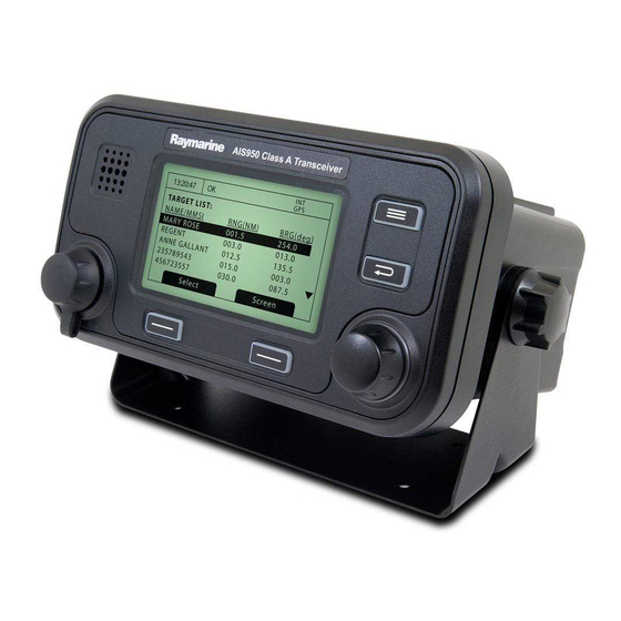
Operation 3.5 Target list The target list screen is shown by default after power up. This screen shows the name (or MMSI), range (in nautical miles) and bearing (in degrees) of other AIS equipped vessels. The nearest vessel is shown at the top of the list. -
Page 15: Own Dynamic Data
Operation The information displayed on this screen includes: ● MMSI - the Maritime Mobile Service Identity for the vessel on which the transceiver is installed. ● Vessel name ● Call sign ● Destination - the current voyage destination ● IMO Number (where applicable) ●... -
Page 16: Received Messages
Operation 3.8 Received messages This screen shows AIS text and Safety Related Messages (SRM) received from other AIS stations. The most recently received message is shown at the top of the list. The date and time of reception, name or MMSI of the sending station and type of message (text or SRM) are shown in the message list. -
Page 17: Alarms Screen
Operation 3.9 Alarms screen This screen shows the status of AIS system alarms. If an active and not yet acknowledged alarm condition exists the alarm icon in the status bar will flash. If an alarm condition occurs whilst not in the menu system an acknowledgement screen will be shown immediately, this is described in section 3.12. -
Page 18: Target Plot Screen
Operation 3.10 Target plot screen The target plot screen shows the location of other AIS equipped vessels and shore stations relative to your own vessel. The target plot screen provides a basic overview of AIS targets and should not be regarded as a substitute for display of AIS information on a dedicated electronic chart display system (ECDIS). -
Page 19: Figure 14 Safety Related Message Notification
Operation 13:20:47 SAFET Y RELATED MESSAGE: Type: Broadcast SRM MMSI: 235687901 NAME: >>MARY ROSE Channel: A Date: 29/01/2010 Back Reply Figure 14 Safety Related Message notification 3.11.2 Sending AIS Text and Safety Related Messages To compose a new text or Safety Related Message (SRM) press the ‘Menu’ key then select the ‘MESSAGES’ sub menu followed by the ‘NEW MESSAGE’... -
Page 20: Handling Alarms
Operation 3.12 Handling alarms The AIS950 transceiver performs self checking functions continuously. If a self check fails an alarm will occur. Possible alarm conditions are listed in Table 2. Alarm condition Description Transmitter malfunction This alarm can occur if there is a fault with the transmitter or if the antenna VSWR exceeds allowable limits. -
Page 21: Entering Text
Operation From the alarm notification screen you have the option to immediately acknowledge the alarm by pressing the ‘ACK’ function key, or to view the active alarms list by pressing the ‘Goto List’ function key. Once an alarm is acknowledged it will remain in the alarms list whilst the underlying alarm condition is active. The presence of active but acknowledged alarm conditions is indicated by continuous display of the alarm icon in the status bar. -
Page 22: Long Range Messages
Figure 17 Text entry 3.14 Long range messages If the AIS950 transceiver is connected to a long range communication system via the long range communications port then long range interrogations may be received. These are requests for information from a distant base station beyond normal AIS operation range. -
Page 23: Figure 18 Long Range Interrogation Notification; Automatic Response Mode Enabled
Operation 13:20:47 Long range interrogation: Date: 31/03/2010 Time: 13:15:39 MMSI: 001245368 Name: >> RES Response automatically sent Ack nowledge Figure 18 Long range interrogation notification; automatic response mode enabled 13:20:47 Long range interrogation: Date: 31/03/2010 Time: 13:15:39 MMSI: 001245368 Name: >>... -
Page 24: Passwords And Security
Operation 3.15 Passwords and security Certain important information stored within the transceiver can not be changed without knowledge of the password. The protected information includes: ● MMSI number ● Name of vessel ● Call sign ● IMO number ● Channel management settings ●... -
Page 25: Figure 22 Main Menu Structure
Operation VOYAGE DATA NAVIGATIONAL STATUS DESTINATION DRAUGHT CARGO/SHIP TYPE NUMBER ON BOARD MESSAGES NEW MESSAGE MESSAGES INBOX SENT MESSAGES LONG RANGE MESSAGES USER SETTINGS KEY BEEP DISPLAY LONG RANGE CONFIGURATION SET LANGUAGE INSTALLATION SET IDENTIFICATION DIMENSIONS CHANGE PASSWORD REGIONAL AREAS SENSOR CONFIGURATION MAINTENANCE SYSTEM INFORMATION... -
Page 26: Figure 23 Main Menu Screen
Operation 13:20:47 MAIN MENU: VOYAGE DATA MESSAGES USER SET TINGS INSTALLATION MAINTENANCE Back Selec t Figure 23 Main menu screen 3.16.1 Voyage data menu The voyage data menu provides quick access to the most commonly changed AIS transceiver parameters. 13:20:47 VOYAGE DATA: Nav Status: >>(15) not defined (default) -
Page 27: Figure 25 The Messages Menu
● Long range messages - view a list of received long range messages as described in section 3.14. 3.16.3 User settings menu The user setting menu provides access to user configurable preferences for the AIS950 transceiver. All user settings are stored within the transceiver and will be maintained if the power supply is switched off. -
Page 28: Figure 27 The Installation Menu
Operation 3.16.4 Installation menu The installation menu provides access to settings that are required during installation of the AIS950 transceiver. Please refer to the installation section of this manual for more detailed information on installation settings and requirements. Some settings in the installation menu are password protected and should only be adjusted by authorised personnel. -
Page 29: Tanker Mode
Operation 3.16.6 Diagnostics Certain diagnostics information is provided to assist with installation and maintenance of the transceiver. This can be accessed via the Maintenance menu. Figure 29 shows the diagnostics menu page. A number of features can be accessed via the diagnostics menu: ●... -
Page 30: Units Display - Speed And Distance
Operation 13:20:47 TANKER MODE: Exiting Tanker Mode Transmit Power is High Power (12.5W ) Change Nav. Status? ( Currently moored ) Back Change Figure 31 Tanker mode exit screen when speed exceeds 3 knots 3.18 Units display - speed and distance When operating in Class A (SOLAS) mode the default units for speed and distance are knots (kn) and nautical miles (nm) respectively. -
Page 31: Installation
Installation Installation The AIS950 AIS transceiver has been designed for ease of installation. The transceiver is a ‘one box’ design containing both the transceiver and display. An external junction box is provided to simplify connection of sensor and display data wiring. A typical system and connection diagram is provided in Figure 32. -
Page 32: What's In The Box
Figure 33 What’s in the box ● AIS950 Class A AIS transceiver The main transceiver and display. ● Data cable A 1m (3.3ft) long, 50 way data cable to connect the transceiver serial data ports to the junction box. -
Page 33: Preparing For Installation
Installation 4.2 Preparing for installation In addition to the items provided with the AIS950 transceiver the following items will be required to complete the installation: 4.2.1 VHF Antenna Connection of a suitable VHF antenna will be required for the AIS transceiver to operate. A standard marine band VHF antenna such as that used with VHF voice radios is sufficient. -
Page 34: Figure 34 Ais Transceiver Dimensions
Installation ● An AC power port should be available near to the pilot plug. A pilot plug is located on the front panel of the AIS transceiver and can also be relocated using the junction box. Please refer to section 4.4.2 for guidance. -
Page 35: Figure 36 Panel Mounting The Ais Transceiver
Installation Figure 36 Panel mounting the AIS transceiver 4.3.2 Step 2 - Installing the junction box The AIS transceiver receives data from the ship’s sensors via the 50 way data cable which connects to the rear of the transceiver. The other end of this cable is connected to the junction box which provides a convenient screw terminal system for connection of ships sensor data cables. -
Page 36: Figure 37 Junction Box Dimensions
4.3.3 Installing the GPS antenna The AIS950 AIS transceiver includes an internal GPS receiver for time synchronisation. An independent GPS antenna is required for this receiver in addition to any GPS equipment already installed on board. For mounting of the GPS antenna supplied with your AIS transceiver you will require a one inch 14 TPI pole mount. -
Page 37: Figure 39 Gps Antenna Location
Figure 39 GPS antenna location GPS antenna connection Figure 40 GPS antenna connection 4.3.4 Installing the VHF antenna The AIS950 AIS transceiver requires a dedicated VHF antenna for communications. A standard marine VHF antenna is suitable. Page 37... -
Page 38: Figure 41 Vhf Antenna Installation
Installation Please note the following guidelines when selecting and locating the AIS VHF antenna: ● The VHF antenna should be located as high as possible and positioned as far from other antennas as possible. ● The VHF antenna should have omnidirectional vertical polarization. ●... -
Page 39: Connecting The Equipment
4.4.2 Data connections The AIS950 transceiver is supplied with a 1m (3.2ft) 50 way data cable for interconnection of the transceiver and junction box. Connect the junction box to the transceiver using the data cable as indicated in Figure 43. - Page 40 4.4.3 Sensor configuration The AIS950 transceiver has seven NMEA0183 (IEC61162-1/2) data ports for connection of ship’s sensors and display equipment as described in Table 3. There are three input ports for ship’s sensor data and three bidirectional ports for connection of display equipment such as Radar or electronic chart displays. It is recommended that an AIS compatible electronic charting system is connected to the AIS950 transceiver for display of AIS targets.
-
Page 41: Figure 44 Junction Box Connections
Installation To transceiver Bidirectional data ports Termination jumpers Sensor data inputs EXT_DISP_IN PILOT_IN DGPS_IN LR_IN SEN1 SEN2 SEN3 GND COM NC GND GND EXT_DISP_OUT PILOT_OUT DGPS_OUT LR_OUT ALARM SHIELD SWITCHES Cable glands Figure 44 Junction box connections Page 41... - Page 42 Installation Junction box signal Data port Description Function label Sensor 1 SEN1 A Sensor port 1 input A Connect to data source, typically ships primary GPS at 4800baud. SEN1 B Sensor port 1 input B This port can be configured to operate at either 4800 or 38400 SEN1 GND Sensor port 1 isolated ground...
-
Page 43: Figure 45 Example Connection To External Display Equipment
Installation An example of connection to external display equipment is provided in Figure 45, and connections to other equipment and sensors follow the same scheme. To determine the ‘A’ and ‘B’ signal lines on external equipment use a digital volt meter to measure the signal line voltage referenced to ground. If the voltmeter shows a negative voltage the ‘A’... -
Page 44: Figure 47 Power Connection
Installation Along with data port connections the junction box also provides connections to the AIS transceiver alarm relay contacts. The common and normally open alarm contacts are duplicates of the alarm relay connections available at the power connector (see Table 5) whilst the normally closed contact is only provided at the junction box. -
Page 45: Figure 48 Pc Data (Rs232) Connection
4.4.6 PC data connection A 9 way D-type connector is provided on the rear panel of the AIS950 transceiver. This interface allows direct connection to a PC RS232 interface and can be used for installation, diagnostics or external display connection. The default configuration for this interface allows connection of an ECDIS or charting system and duplicates the ‘External display’... -
Page 46: Configuring The Ais950 Transceiver
● Power has been connected to the transceiver and the transceiver is operational (the display is active). The following configuration instructions assume the installer is familiar with the AIS950 user interface, details of which can be found in the Operation section of this manual. -
Page 47: Figure 49 Vessel Dimensions Measurement
Installation To enter the GNSS antenna locations go back to the main menu and select the ‘Dimensions’ then ‘Internal’ or 'External’ option as appropriate. Dimensions for both the internal and external GNSS antennas must be entered if an external GNSS is connected to the AIS transceiver. The antenna dimensions should be entered in metres according to the diagram provided in Figure 49. - Page 48 Installation Type Vessel type code Reserved (do not use) 1[n] Wing in ground craft 2[n] Fishing Towing Towing and length of tow exceeds 200m or breadth exceeds 25m Engaged in dredging or underwater operations Engaged in diving operations Engaged in military operations Sailing Pleasure craft (HSC) High speed craft...
-
Page 49: Changing The Password
‘Target list' screen is displayed. Check that data from other AIS equipped vessels is displayed. The AIS950 transceiver is now operational and should remain powered unless authorised by the local maritime authority. The installation record at the rear of this manual should be completed and left on board the vessel. -
Page 50: Figure 51 Regional Area Editing Screen
Installation To create the new area setting press the ‘New' function key and the edit screen shown in Figure 51 will be displayed. 13:20:47 EDIT REGIONAL AREA: In Use: Time of In Use: --:--:-- Info Source: Not Available Channel A: 2087 Channel B: 2088... -
Page 51: Technical Specifications
Technical Specifications Technical Specifications 5.1 Applicable equipment standards IEC61993-2 (2001) Class A shipborne equipment of the universal automatic identification system (AIS) – Operational and performance requirements, methods of test and required test results IEC60945 (2002) Maritime navigation and radiocommunication equipment and systems – General requirements –... -
Page 52: Display And User Interface
Technical Specifications 5.5 Display and user interface Display 248 x 128 pixel monochrome LCD with adjustable backlight Keypad Two function keys and two menu keys with adjustable backlight Rotary control Encoder with push function and adjustable backlight Sounder 2.4kHz buzzer 5.6 Internal GPS Receiver channels 16 channels... -
Page 53: Dsc Receiver
Technical Specifications 5.9 DSC receiver Number of receivers Frequency 156.525MHz (Channel 70) Channel bandwidth 25kHz Sensitivity -107dBm @ BER <10 Modulation mode 25kHz AFSK Adjacent channel selectivity 70dB Spurious response rejection 70dB 5.10 RF connections VHF antenna connection SO-239 / UHF VHF port impedance 50 Ohms GPS antenna connection... -
Page 54: Power And Data Connector Information
Technical Specifications 5.12 Power and data connector information Power connector Mating half BSD-04PMMS-SC7001 BSD-04BFFM-SL6A02 Pilot plug connector TYCO Mating half TYCO 206486-2 206485-1 50 way data connector Harting Mating half Harting 09665526612 09670505615 RS232 connector Harting Mating half Harting 09661526612 09670095615 Page 54... -
Page 55: Technical Reference
Technical reference Technical reference 6.1 Interface sentences The IEC61162 sentences accepted by and output by the transceiver serial data ports are listed in Table 10 below. Data port Input sentences Output sentences Sensor 1 DTM, GBS, GGA, GLL, GNS, HDT, Sensor 2 RMC, ROT, VBW, VTG Sensor 3... -
Page 56: Transmission Intervals
Technical reference 6.2 Transmission intervals The IEC61162 sentences are in general output in response to a specific event, such as initiation of a binary message via the user interface. Certain messages are output over the ports at regular transmission intervals. Table 11lists each sentence type and the transmission interval. -
Page 57: Bi-Directional Data Ports
Technical reference 6.4 Bi-directional data ports The input circuitry of the bi-directional data ports is identical to the input circuitry for the sensor data input ports described in the preceding section. The output circuitry consists of a differential line driver IC (Texas Instruments AM26LV31E) and is shown in Figure 54. - Page 58 Technical reference 6.8.1 ABM - Addressed binary and safety related message This sentence allows external applications to transmit binary and safety messages using the AIS transceiver via AIS messages 6 and 12. !--ABM,x,x,x,xxxxxxxxx,x,x.x,s--s,x*hh<CR><LF> Field Description number Total number of sentences needed to transfer the message Sentence number Sequential Message identifier xxxxxxxxx =...
- Page 59 Technical reference 6.8.3 ACK - Acknowledge alarm This sentence is used to acknowledge an alarm condition reported by the transceiver. $--ACK,xxx,*hh<CR><LF> Field Description number xxx = Identification number of the alarm source to be acknowledged. 6.8.4 AIR - AIS Interrogation request This sentence supports ITU-R M.1371 message 15.
- Page 60 Technical reference 6.8.6 DTM - Datum reference Logical geodetic datum and datum offsets from a reference datum. $--DTM,ccc,a,x.x,a,x.x,a, x.x,ccc*hh<CR><LF> Field Description number ccc = Local datum Local datum subdivision code - NOT USED x.x, a = Lat offset, min, N/S - NOT USED x.x,a = Longitude offset, min, E/W - NOT USED x.x =...
- Page 61 Technical reference $--GBS, hhmmss.ss, x.x, x.x, x.x, xx, x.x, x.x, x.x *hh <CR><LF> Probability of missed detection for most likely failed satellite - NOT USED Estimate of bias on most likely failed satellite - NOT USED Standard deviation of bias estimate - NOT USED 6.8.8 GGA - Global positioning system (GPS) fix data This sentence provides time, position and fix related data from a GPS receiver.
- Page 62 Technical reference $--GLL, llll.ll, a, yyyyy.yy, a, hhmmss.ss, A, a *hh<CR><LF> hhmmss.ss Time of position (UTC) Status: A = data valid V = data invalid Mode indicator: A = Autonomous D = Differential E = Estimated (dead reckoning) M = Manual input S = Simulator N = Data not valid 6.8.10 GNS - GNSS fix data...
- Page 63 Technical reference 6.8.12 LRF - Long range function This sentence is used in long range interrogation requests and interrogation replies. $--LRF,x,xxxxxxxxx,c--c,c--c,c--c*hh<CR><LF> Field Description number Sequence number, 0 to 9 xxxxxxxxx MMSI of requestor c--c Name of requestor, 1 to 20 character string c--c Function request, 1 to 26 characters from: A = Ship’s name, call sign and IMO number...
- Page 64 Technical reference 6.8.14 RMC - Recommended minimum specific GNSS data Time, date, position, course and speed information provided by a GNSS receiver. All data fields should be provided and null fields only used when data is temporarily unavailable. $--RMC, hhmmss.ss, A, llll.ll,a, yyyyy.yy, a, x.x, x.x, xxxxxx, x.x,a, a*hh<CR><LF> Field Description number...
- Page 65 Technical reference $--SSD,c--c,c--c,xxx,xxx,xx,xx,c,aa*hh<CR><LF> Pos. ref., "B," distance from stern, 0 to 511 metres Pos. ref., "C," distance from port beam, 0 to 63 metres Pos. ref., "D," distance from starboard beam, 0 to 63 metres DTE indicator flag Source identifier 6.8.17 VBW - Dual ground / water speed This sentence conveys both water and ground referenced speed data.
-
Page 66: Output Data Sentence Formats
Technical reference $--VSD,x.x,x.x,x.x,c--c,hhmmss.ss,xx,xx,x.x,x.x*hh<CR><LF> Estimated month of arrival at destination, 00 to 12 (UTC) Navigational status, 0 to 15 Regional application flags, 0 to 15 6.8.19 VTG - Course over ground and ground speed The vessels actual course and speed relative to ground. $--VTG, x.x, T, x.x, M, x.x, N, x.x, K,a*hh<CR><LF>... - Page 67 Technical reference 6.9.2 ACA - AIS Channel assignment message See section 6.8.2. 6.9.3 ALR - Set alarm state This sentence is used to indicate local alarm conditions and status along with alarm acknowledgement status. $--ALR,hhmmss.ss,xxx,A, A,c--c*hh<CR><LF> Field Description number hhmmss.ss Time of alarm condition change, UTC Local alarm number (identifier) Alarm condition (A = threshold exceeded, V = not exceeded)
- Page 68 Technical reference $--LR2,x,xxxxxxxxx,xxxxxxxx,hhmmss.ss,llll.ll,a,yyyyy.yy,a,x.x,T,x.x,N*hh<CR><LF> hhmmss.ss Time of position, UTC llll.ll,a Latitude, N/S yyyyy.yy,a Longitude, E/W x.x,T Course over ground, degrees True x.x,N Speed over ground, knots 6.9.7 LR3 - Long range reply for function requests ‘I’, ‘O’, ‘P’, ‘U’, and ‘W’ The LR3 sentence contains the information requested by the I, O, P, U and W function characters.
- Page 69 Technical reference 6.9.9 VDM - VHF data link message This sentence is used to transfer the contents of a received AIS message (as defined in ITU-R M.1371) as received on the VHF Data Link (VDL) using 6 bit ASCII data encapsulation. !--VDM,x,x,x,a,s--s,x*hh<CR><LF>...
-
Page 70: Drawings
Drawings Drawings 7.1 AIS transceiver overall dimensions 172 mm 157 mm 195 mm 112 mm 7.2 Junction box overall dimensions 165 mm 178 mm 76 mm Page 70... -
Page 71: Dash Mount Bracket Fixing Holes (Drill Drawing) (Not To Scale)
Drawings 7.3 Dash mount bracket fixing holes (drill drawing) (not to scale) Drill for screw size No. 8 (4-PL) 120.0mm Tap drill size No. 29 (3mm drill is sufficient) 7.4 GPS antenna drawing (not to scale) 10m RG58 cable TNC (male) Page 71... - Page 72 Drawings Page 72...
-
Page 73: Installation Record
Installation record Installation record The following installation record should be completed and retained on board the vessel once the AIS transceiver has been installed and commissioned. Vessel details Vessel name Flag state IMO number MMSI number Owner Radio call sign Type of vessel Gross registered tonnage Length (m) - Page 74 Installation record Connected equipment type (where applicable note equipment model and AIS data port in each case) (D)GPS receiver Gyro compass ROT indicator Speed log ECDIS Radar Other equipment Power supply The following drawings should be provided and attached to this installation record: ●...
- Page 75 201-0221:1...
Need help?
Do you have a question about the AIS950 and is the answer not in the manual?
Questions and answers