Table of Contents
Advertisement
Advertisement
Table of Contents

Related Manuals for Raymarine AIS500


Summary of Contents for Raymarine AIS500
- Page 1 AUTOMATIC IDENTIFICATION SYSTEM AIS500 Transceiver Installation instructions...
- Page 3 Trademarks and registered trademarks Autohelm, HSB, RayTech Navigator, Sail Pilot, SeaTalk and Sportpilot are UK registered trademarks of Raymarine UK Limited. Pathfinder and Raymarine are UK registered trademarks of Raymarine Holdings Limited. 45STV, 60STV, AST, Autoadapt, Auto GST, AutoSeastate, AutoTrim, Bidata, G Series, HDFI, LifeTag, Marine Intelligence, Maxiview, On Board, Raychart, Raynav, Raypilot, RayTalk, Raystar, ST40, ST60+, Seaclutter, Smart Route, Tridata, UniControl and Waypoint Navigation are trademarks of Raymarine UK Limited.
-
Page 5: Table Of Contents
Contents Chapter 1 Introduction ..........7 Chapter 5 Post installation procedures....35 Applicability ..............7 5.1 Switching on ............. 36 Safety information............7 5.2 Configuration ............36 General information ............8 5.3 Checking for interference........... 37 Requirements for USA & Canada ........9 5.4 Using AIS .............. -
Page 7: Chapter 1 Introduction
Ensure the boat’s power supply is switched OFF RF radiation statement before starting to install this product. Do NOT connect Your Raymarine AIS500 transceiver generates and radiates radio or disconnect equipment with the power switched on, frequency (RF) electromagnetic energy (EME). -
Page 8: General Information
Raymarine AIS500 is an AIS Class B transceiver, and is intended It is important that you register your product to receive full warranty for world wide use aboard leisure marine boats and workboats not benefits. Your unit package includes a bar code label indicating the covered by International Maritime Organization (IMO) and Safety of serial number of the unit. -
Page 9: Requirements For Usa & Canada
Compliance statement If a valid MMSI number is not entered, the AIS500 will enter Silent This device complies with part 15 of the FCC Rules. Operation is Mode and will not transmit. However, it will still operate as a receiver. - Page 10 MMSI that has not been properly assigned to the end user or to Attention: DOSP otherwise input any inaccurate data in this device. The MMSI and Static Data must be entered only by a Raymarine dealer or 300 Slater Street other appropriately qualified installer of marine communications Ottawa, Ontario equipment on board vessels.
-
Page 11: Requirements For Areas Outside Of Usa & Canada
A nine-digit Maritime Mobile Service Identity (MMSI) number is requirements is 3.5 meters. Do not operate the transceiver when required to operate the AIS500 Transceiver. In some areas, a radio anyone is within the MPE radius of the antenna, unless shielded operator licence is required before an MMSI number will be issued. -
Page 12: Declaration Of Conformity
Declaration of Conformity Netherlands Czech Republic Denmark Norway Estonia Poland Finland Portugal France Romania Germany Slovakia Greece Slovenia Hungary Spain Iceland Sweden Ireland Switzerland Italy Turkey Latvia United Kingdom... -
Page 13: System Information
AIS should be used only to augment radar information, not substitute Class A Class B Class B Data (receive) (send) (receive) Classes of AIS Ship’s name Your AIS500 is a transceiver that receives messages from and Type transmits messages to vessels carrying Class A or Class B transceivers. Introduction... - Page 14 Note: The reporting rates shown here are for reference and Antenna location may not be the rate at which information is actually received by an AIS500 Transceiver. This is dependent on a number of Draft factors, including but not limited to antenna height, gain and signal interference.
- Page 15 Other AIS sources Source Reporting rate Search and Rescue (SAR) aircraft 10 seconds Aids to navigation 3 minutes AIS base station 10 seconds or 3.33 seconds, depending on operating parameters Introduction...
-
Page 17: Chapter 2 Planning The Installation
Chapter 2: Planning the installation Chapter contents • 2.1 EMC installation guidelines on page 18 • 2.2 Parts supplied on page 19 • 2.3 Tools required on page 19 • 2.4 Basic system on page 20 Planning the installation... -
Page 18: Emc Installation Guidelines
Requirement for ferrites on non-Raymarine cables • Raymarine equipment and cables connected to it are: If your Raymarine equipment is to be connected to other equipment using a cable not supplied by Raymarine, a suppression ferrite – At least 1 m (3 ft) from any equipment transmitting or cables MUST always be attached to the cable near the Raymarine unit. -
Page 19: Parts Supplied
2.2 Parts supplied 2.3 Tools required Check all parts are present. Ensure you have these tools before starting installation. AIS500 Transceiver GPS Antenna 1/4" (3.2mm) Thumb Drill bit nuts (x 2) Mounting studs (x 2) 3.2 ft (1. m) AIS to VHF Antenna connector cable... -
Page 20: Basic System
SeaTalk 10.76 in (273.3 mm) NMEA0183 (38.4 baud) NMEA0183 (4.8 baud) Compass minimum safe distance: 39 in (1 m) RS232 Site requirements When planning the installation, take the following site requirements for the AIS500 transceiver and GPS antenna, into account. - Page 21 Power supply or other structures) that could block line-of-sight to the sky. The AIS500 transceiver requires a 12 V dc or 24 V dc power supply, • As low as possible, to keep the antenna as stable as possible. typically from a circuit breaker on the boat’s power panel or from a The more stable the unit, the more effectively it will track satellites fuse block near the transceiver.
- Page 22 , refer to the SeaTalk Reference Manual, and ensure that with this product connected, the maximum permitted Load Equivalence Number (LEN) value for the system will not be exceeded. Note that the AIS500 transceiver has a SeaTalk LEN value of 1.
-
Page 23: Chapter 3 Cables & Connections
Chapter 3: Cables & connections Chapter contents • 3.1 Cable types and length on page 24 • 3.2 Routing cables on page 24 • 3.3 Transceiver connections on page 25 • 3.4 Cable shielding on page 26 Cables & connections... -
Page 24: Cable Types And Length
• Do NOT bend cables excessively. Wherever possible, ensure a minimum bend radius of 100 mm. • Ensure that any non-Raymarine cables are of the correct quality and gauge. For example, longer power cable runs may require larger wire gauges to minimize voltage drop along the run. -
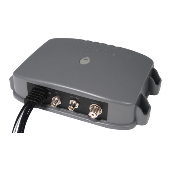
Page 25: Transceiver Connections
GPS connections The GPS supplied as part of the AIS500 system has a fitted 10 m (33 ft) cable to connect to the AIS500 transceiver GPS connector. Power NMEA connections... -
Page 26: Cable Shielding
• The 4800 baud wires connect to the appropriate points on the VHF radio or other NMEA0183 4800 baud input/output device. • The 38400 baud wires connect to appropriate Raymarine MFDs. The NMEA0183 port on each MFD connected in this manner... -
Page 27: Chapter 4 Installation Procedures
Chapter 4: Installation procedures Chapter contents • 4.1 Fitting transceiver on page 28 • 4.2 Fitting GPS antenna on page 29 • 4.3 Connecting up on page 31 Installation procedures... -
Page 28: Fitting Transceiver
4.1 Fitting transceiver Ensure that the intended installation site meets the conditions described under Site requirements, mark and drill the mounting holes, then fit the transceiver as shown in the following illustrations. Note: This procedure shows how to mount the transceiver vertically, which is the recommended method. -
Page 29: Fitting Gps Antenna
4.2 Fitting GPS antenna To fit the GPS antenna: 1. Select a suitable location for the GPS antenna as described under Site requirements. 2. Fit your GPS antenna using either the Surface mounting or Pole mounting procedure, as appropriate. 3. Ensuring the conditions in Running cables are fulfilled, run the GPS antenna cable to the AIS transceiver. - Page 30 5. Ensuring you do not trap the cable, place the GPS antenna on the pole mount adaptor so the screw holes align, then secure the antenna with the 2 screws retained at step 2. Antenna Pole mount adaptor 1. Ensuring that the Site requirements are met, securely attach the pole to a suitable, secure point.
-
Page 31: Connecting Up
4.3 Connecting up The transceiver will not transmit, but will still receive. Carry out the following procedures to connect up the AIS500 system: Connecting to VHF • Connecting GPS Ensure power to the ship’s VHF set is switched off, then connect the AIS500 transceiver by carrying out the Connecting RF and the •... - Page 32 Ensure power to the multi-function displays is switched off, then Equivalence Number (LEN) value for the system to be exceeded connect the AIS500 transceiver by carrying out either the Connect (see Site Requirements). using NMEA0183 OR the Connect using SeaTalk procedure.
-
Page 33: Connecting Power
5 A fuse or equivalent automatic circuit optimum connection to the power source. breaker. Connect the AIS500 transceiver power cable to either a 12 V dc or 24 V dc power source as follows: Sharing a breaker 1. - Page 34 Power supply Connect to 12 V dc, or Black Power supply 24 V dc D11649-1...
-
Page 35: Chapter 5 Post Installation Procedures
Chapter 5: Post installation procedures Chapter contents • 5.1 Switching on on page 36 • 5.2 Configuration on page 36 • 5.3 Checking for interference on page 37 • 5.4 Using AIS on page 38 Post installation procedures... -
Page 36: Switching On
Important: Before starting any AIS configuration procedure, SWITCH OFF all associated multi-function displays (MFDs), otherwise you will not be able to correctly configure your AIS500 transceiver. In the USA, it is a legal requirement that the configuration is... -
Page 37: Checking For Interference
5.3 Checking for interference You can use the supplied ProAIS PC software, to check the vessel data programmed into your AIS500. If this information is incorrect please contact your Raymarine dealer before using the transceiver. Post installation check If you have installed any system aboard a boat or made other Areas outside of USA changes to the boat’s electronic systems (radar, VHF radio etc.),... -
Page 38: Using Ais
5.4 Using AIS The exact method of using AIS depends on which type of Raymarine multi-function display (MFD) you are using. Refer to the handbook for your MFD for information on using AIS. -
Page 39: Chapter 6 Diagnostics
Chapter 6: Diagnostics Chapter contents • 6.1 Status indication on page 40 • 6.2 Troubleshooting on page 41 Diagnostics... -
Page 40: Status Indication
Running in Silent Mode BLUE (flash) Each time AIS data is received The current operating status of the AIS500 transceiver is shown by a STATUS LED on the bottom of the unit. Fault condition. Refer to the Troubleshooting section S TATUS... -
Page 41: Troubleshooting
VHF radio information the proAIS application) No vessel data At the relevant Raymarine multi function display: • Place the cursor over the targeted vessel and ensure the AIS DATA soft key is not set to OFF •... -
Page 43: Chapter 7 Specifications
Chapter 7: Specifications Chapter contents • 7.1 General on page 44 • 7.2 Transceiver on page 44 • 7.3 GPS Receiver on page 45 Specifications... -
Page 44: General
PC RS232 – 9 Way D Type NMEA0183 HS – stripped wires NMEA0183 LS – stripped wires Power – stripped wires SeaTalk - proprietary Raymarine connector NMEA sentences !AIVDO, !AIVDM, !AIALR, and !AITXT • With NMEA GPS $GPGLL, $GPGGA, $GPVTG, $GPGSV, $GPGSA,... -
Page 45: Gps Receiver
7.3 GPS Receiver Receiver channels Receiver sensitivity Acquisition -140 dBm Tracking -150 dBm Nominal Time to First Fix 34 seconds Specifications... - Page 48 www.raymarine.com...
Need help?
Do you have a question about the AIS500 and is the answer not in the manual?
Questions and answers