Raymarine RAY53 Installation & Operation Instructions
Hide thumbs
Also See for RAY53:
- Installation & operation instructions (190 pages) ,
- User manual (47 pages) ,
- Installation and operation instruction manual (208 pages)

Related Manuals for Raymarine RAY53


Summary of Contents for Raymarine RAY53
- Page 1 RAY53/63/73 Installation & operation instructions English (en-US) Date: 06-2018 Document number: 81381-1 © 2018 Raymarine UK Limited 81381-1-Ray53_63_73_Install_and_Ops_PRINT.pdf 1 6/13/2018 2:30:09 PM...
- Page 2 81381-1-Ray53_63_73_Install_and_Ops_PRINT.pdf 2 6/13/2018 2:30:09 PM...
- Page 3 You may print no more than three copies of this manual for your own use. You may not make any further copies or distribute or use the manual in any other way including without limitation exploiting the manual commercially or giving or selling copies to third parties. Software updates Check the Raymarine website for the latest software releases for your product. www.raymarine.com/software Product documentation The latest versions of all English and translated documents are available to download in PDF format from the website: www.raymarine.com/manuals.
- Page 4 81381-1-Ray53_63_73_Install_and_Ops_PRINT.pdf 4 6/13/2018 2:30:09 PM...
-
Page 5: Table Of Contents
Additional information – Ray53........ - Page 6 4.2 Connections overview — Ray53 ........
- Page 7 5.17 GNSS (GPS) set up ..........51 6.6 Group calls.
- Page 8 12.1 Technical specification — Ray53 ........88...
-
Page 9: Chapter 1 Important Information
Grounding this product to a vessel’s RF Contact your Raymarine dealer for further details, and ground may cause galvanic corrosion. refer to the separate warranty document packed with Compliance Statement (Part 15.19) -
Page 10: Innovation, Science And Economic Development Canada
Canada (ISED) Failure to observe these guidelines may expose those within the Maximum Raymarine does not warrant that this product is error-free This device complies with License-exempt RSS Permissible Exposure (MPE) radius to RF or that it is compatible with products manufactured by standard(s). -
Page 11: Product Disposal
Please check the Raymarine of waste electrical and electronic equipment at a website (www.raymarine.com) to ensure you have the recycling center or other collection point. - Page 12 81381-1-Ray53_63_73_Install_and_Ops_PRINT.pdf 12 6/13/2018 2:30:09 PM...
-
Page 13: Chapter 2 Document And Product Information
• 2.2 Product overview on page 15 • 2.3 Applicable products on page 15 • 2.4 Parts supplied – Ray53 on page 17 • 2.5 Parts supplied – Ray63 / Ray73 on page 17 • 2.6 Licensing on page 18 •... -
Page 14: Product Documentation
Ray63 / Ray73 mounting 87219 manufacture. • Raymarine user manuals are also available to template download free-of-charge from the Raymarine All images are provided for illustration purposes only. website, in the popular PDF format. These PDF... -
Page 15: Product Overview
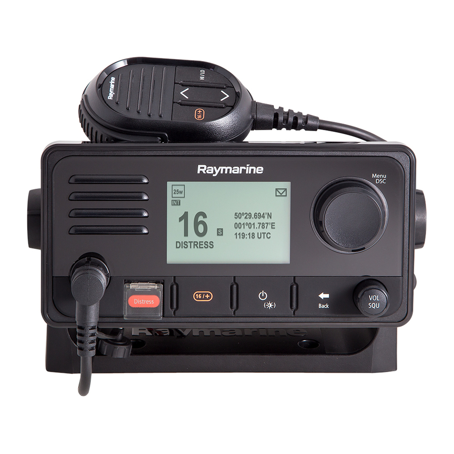
2.2 Product overview 2.3 Applicable products Part Name number Features The Ray53, Ray63 and Ray73 are 12 V dc, Class D This document is applicable to the following products: E70524 Ray53 • SeaTalkng ® Digital Selective Calling (DSC) VHF radios. DSC enables... -
Page 16: Required Additional Components
GNSS (GPS) receiver using an external antenna. enabling DSC distress message information and position This product is NOT compatible with the following Part number Description data on your MFD screen. legacy Raymarine multifunction displays. A80288 Passive GNSS (GPS) antenna Compatible LightHouse™ 3 MFDs Legacy MFDs Axiom™... -
Page 17: Parts Supplied - Ray53
2.5 Parts supplied – Ray63 / Item Description Ray73 SeaTalkng ® blanking plug The parts listed below are supplied with the Ray53. The parts listed below are supplied with the Ray63 and SeaTalkng ® 400 mm (15.7 in.) spur cable Ray73. Item... -
Page 18: Licensing
Form 605. FCC ID PJ5–RAY60 In the United States of America, the MMSI and Static Data must be entered only by a Raymarine® dealer FCC Type Parts 2, 15 and 80 Canada licensing requirements or other appropriately qualified installer of marine accepted communications equipment on board vessels. -
Page 19: Automatic Transmitter Identification System (Atis)
Your ATIS ID should be programed into your product to perform the software update, alternatively refer to using the instructions provided. the instructions provided on the software download area for your product on the Raymarine website: Note: ww.raymarine.com/software. Contracting RAINWAT countries include: Austria, •... - Page 20 81381-1-Ray53_63_73_Install_and_Ops_PRINT.pdf 20 6/13/2018 2:30:10 PM...
-
Page 21: Chapter 3 Installation
Chapter 3: Installation Chapter contents • 3.1 Selecting a location on page 22 • 3.2 EMC installation guidelines on page 23 • 3.3 Product dimensions on page 23 • 3.4 Mounting on page 25 Installation 81381-1-Ray53_63_73_Install_and_Ops_PRINT.pdf 21 6/13/2018 2:30:10 PM... -
Page 22: Selecting A Location
(such as in an engine room or near fuel tanks). Raymarine® declares a Maximum Permissible Exposure Electrical interference (MPE) radius of 1.8 meters (5.9 ft.) for this system, Select a location that is far enough away from devices... -
Page 23: Emc Installation Guidelines
3.2 EMC installation guidelines 3.3 Product dimensions Suppression ferrites • Raymarine cables may be pre-fitted or supplied with Raymarine® equipment and accessories conform to Product dimensions — Ray53 suppression ferrites. These are important for correct the appropriate Electromagnetic Compatibility (EMC) EMC performance. -
Page 24: Product Dimensions - Ray63 / Ray73
192.5 mm (7.6 in) Bracket mount dimensions The Fistmic’s fitted, coiled lead can be extended comfortably to approximately 1 meter (3.3 ft.) 121 mm (4.8 in) Product dimensions - Wired handset 173.75 mm (6.8 in) (Raymic) 25 mm (1 in) Product dimensions —... -
Page 25: Mounting
3.4 Mounting Mounting options The product can be mounted in the following Tools required for installation configurations. 1. Mark the location of the bracket mounting holes on the mounting surface. 2. Drill holes for the mounting fixings using a drill with Bracket mount —... -
Page 26: Panel Mounting - Ray53
Panel mounting — Ray53 1. Using a drill and a 4 mm (5/32) drill bit, drill out the 4. Using a suitable saw, cut along the inside edge of 4 mounting holes. the cut-out line. Removing the mounting hole covers 5. -
Page 27: Panel Mounting - Ray63 / Ray73
Panel mounting — Ray63 / Ray73 Note: The supplied gasket provides a seal between the Drilling out the mounting holes unit and a suitably flat and stiff mounting surface or Before panel mounting the Radio the mounting holes binnacle. The gasket should always be used. It may must be drilled out. -
Page 28: Fistmic Mounting
Fistmic mounting Handset (wired) mounting using the Pass-through panel kit mounting holster The Fistmic can be mounted by following the steps When installing handsets, the pass-through panel kit below. Whilst only the Fistmic is pictured, you can should be used to secure the cable’s connector to the Follow the steps below to mount the Wired handset also mount the Handset using the same Hook plate panel the cable has to pass through. - Page 29 the location of the screw holes and the center hole Note: on the mounting panel. Drill bit, tap size and tightening torque is dependent on the thickness and type of material the unit is to be mounted on. To ensure that the handset’s connector points down when connected, orientate the mounting plate so that the lanyard grove is pointing straight up.
- Page 30 81381-1-Ray53_63_73_Install_and_Ops_PRINT.pdf 30 6/13/2018 2:30:11 PM...
-
Page 31: Chapter 4 Cables And Connections
Chapter 4: Cables and connections Chapter contents • 4.1 General cabling guidance on page 32 • 4.2 Connections overview — Ray53 on page 33 • 4.3 Connections overview — Ray63 / Ray73 on page 33 • 4.4 Power connection on page 34 •... -
Page 32: General Cabling Guidance
Requirement for ferrites on non-Raymarine cables Coil any extra cable and tie it out of the way. If your Raymarine equipment is to be connected to other • Where a cable passes through an exposed bulkhead equipment using a cable not supplied by Raymarine, or deckhead, use a suitable watertight feed-through. -
Page 33: Connections Overview - Ray53
Ray53 Ray63 / Ray73 The connectors below are used to connect the supplied The following connections are available on the Ray53. The following connections are available on the Ray63 Fistmic and / or the optional Wired (Raymic) handset to and Ray73. -
Page 34: Power Connection
If you are unsure how to provide the correct level of protection, please consult an 5. Power supply negative (-) Black wire. authorized Raymarine dealer or a suitably qualified Grounding professional marine electrician. 6. Suitable waterproof connection (Radio is supplied with bullet crimps on power supply wires.) - Page 35 dedicated Power cable extensions advice provided in • The distribution point should be fed from the vessel’s • The power cable for each unit in your system should the product’s documentation. primary power source by 8 AWG (8.36 mm ) cable. be run as a separate, single length of 2-wire cable from the unit to the vessel's battery or distribution •...
-
Page 36: Fistmic Connection (Ray63 / Ray73 Only)
4.5 Fistmic connection (Ray63 / 4.6 Secondary handset station Handset extension cables Ray73 only) (Ray63 / Ray73 only) Handset station cabling can be extended using approved extension cables. Front connection The Raymic handset accessory can be connected to the The maximum length of cable from the Handset to the Secondary station connector located on the rear of the Base station should not exceed 50 m (164 ft) radio, this will create a second fully functional station. -
Page 37: Seatalkng ® / Nmea 2000 Connection
4.7 SeaTalkng ® / NMEA 2000 4.8 NMEA 0183 connection Connecting SeaTalkng ® cables connection The NMEA 0183 wires can be used to connect the unit to a NMEA 0183 GNSS (GPS) receiver or MFD. Your product can transmit and receive data to and from devices connected on SeaTalkng ®... -
Page 38: Connecting A Vhf Antenna
4.9 Connecting a VHF antenna 4.10 GNSS (GPS) antenna 4.11 Passive speaker connection connection The radio must be connected to a suitable VHF antenna A passive speaker (A80542) can be connected using the (not supplied). The antenna connection must be RCA lead on the radio or on the handset adaptor cable. -
Page 39: Loud Hailer Connection (Ray73 Only)
4.12 Loud hailer connection (Ray73 only) A Loud hailer (M95435) can be connected to the radio using the loud hailer wires. Positive (+) hailer wire (Purple) Negative (-) hailer wire (Gray) Cables and connections 81381-1-Ray53_63_73_Install_and_Ops_PRINT.pdf 39 6/13/2018 2:30:12 PM... - Page 40 81381-1-Ray53_63_73_Install_and_Ops_PRINT.pdf 40 6/13/2018 2:30:12 PM...
-
Page 41: Chapter 5 Getting Started
Chapter 5: Getting started Chapter contents • 5.1 Controls and interface on page 42 • 5.2 Handset controls on page 42 • 5.3 Powering the unit on on page 43 • 5.4 Powering the unit off on page 44 • 5.5 Homescreen overview on page 44 •... -
Page 42: Controls And Interface
5.1 Controls and interface 5.2 Handset controls Fistmic The Handset’s controls are shown below. The controls and interface available are as follows: Base station PTT (Push to Talk) — Press and hold to send a voice message. Release to return to receive mode. Note: The maximum transmit time is limited to 5 minutes to prevent un-intentional transmissions Built-in speaker... -
Page 43: Powering The Unit On
5.3 Powering the unit on 9. HI/LO — Press to switch between High (25 W) and With the Base station powered On: low (1 W) transmit power. 1. Press and hold the Power button, located on the top With the radio connected to a power supply the power of the Handset, for 2 seconds. -
Page 44: Powering The Unit Off
5.4 Powering the unit off 5.5 Homescreen overview • s = Simplex — Simplex channels transmit and receive on the same frequency. The information below describes the on-screen With the unit powered on: • d = Duplex — Duplex channels use separate characters and symbols which are shown on the 1. -
Page 45: Main Menu Overview
Main menu overview Symbol Name Description Symbol Name Sub-options The main menu is accessed by Pressing the OK button Receive Indicates the * Weather Mode • Weather from the Homescreen. radio is currently Homescreen receiving a transmission Weather Indicates that the * Scan Mode •... -
Page 46: Shortcut List
5.6 Shortcut list Symbol Name Sub-options Note: * Menu items not available when radio has ATIS ** Intercom • Intercom Pressing the Power button once while the radio is enabled or if the radio has been pre-programed in switched on will open the Shortcuts list. The Shortcuts MARCOM-C mode. -
Page 47: Shared Brightness
5.7 Shared Brightness 5.8 Initial startup • all units to be compatible with the Shared Brightness function (see list of compatible units above). You can set up Shared Brightness groups which enables Unless your radio has been pre-programmed; the first •... -
Page 48: Accessing The Menu
5.9 Accessing the menu 5.10 Selecting a language 5.11 Switching on the AIS receiver The radio’s various options and settings are contained The language the radio uses can be changed. within the menu. From the Main menu: If your radio includes a built-in AIS receiver then it can be enabled and disabled as follows: 1. -
Page 49: Selecting A Network Type
If you store an incorrect MMSI number or NMEA 2000 Standard speed (4,800) to confirm each number and move to the next digit. ATIS ID in your product, it will have to be reset by an authorized Raymarine ® dealer. NMEA 0183 High Speed High speed (38,400) You should only enter the unique 9 digit MMSI number provided by your licensing authority. -
Page 50: Entering Your Atis Id
4. If the ATIS ID has been pre-filled, check it carefully ATIS ID in your product, it will have to be against your issued ATIS ID. reset by an authorized Raymarine ® dealer. 5. To enter your ATIS ID manually, use the Rotary knob... -
Page 51: Changing The Radio Region
If no position data is available then the latitude, longitude and time can be entered manually so that it can be included in DSC distress transmissions. Position data received from other vessels can be displayed on a connected Raymarine® multifunction display. 1. Select Set-up. Enabling and disabling the internal 2. -
Page 52: No Position Data
5.18 Station priority (Ray63 and No position data Selecting (GNSS) GPS information to display Ray73 only) If no position data is available or position data becomes unavailable; after 10 minutes an audible warning is You can change the GNSS (GPS) data that is displayed sounded, the GNSS (GPS) icon flashes and the No The Ray63 and Ray73 can have a Local Fistmic, on the Homescreen. -
Page 53: Chapter 6 Digital Selective Calling (Dsc)
Chapter 6: Digital selective calling (DSC) Chapter contents • 6.1 Digital Selective Calling (DSC) on page 54 • 6.2 Distress calls on page 55 • 6.3 Urgency calls on page 57 • 6.4 Safety calls on page 57 • 6.5 Individual (routine) calls on page 58 •... -
Page 54: Digital Selective Calling (Dsc)
6.1 Digital Selective Calling The call is automatically repeated at approximately 4 Routine calls are made on channel 70 using the minute intervals until it is acknowledged either by a dedicated Maritime Mobile Service Identity (MMSI) (DSC) coast radio station (CRS) or a vessel within radio range. number of the station to be contacted, selecting a Distress calls must be followed by a MAYDAY call on VHF working channel and sending the call. -
Page 55: Distress Calls
6.2 Distress calls 1. Press and hold the DISTRESS button for 3 seconds. OVER 4. Release the PTT button. Once the DISTRESS button is pressed a 3 second Making a designated distress call 5. If an acknowledgement is not received then repeat count down will begin, when the count down reaches steps 2 to 4 above. -
Page 56: Receiving A Distress Call
When connected to a Raymarine ® multifunction display (MFD) the position Manually relaying a distress call data from the distress call can also be displayed in the Chart application. -
Page 57: Distress Relays Sent By Other Stations
6.3 Urgency calls 6.4 Safety calls OVER Distress relays sent by other stations Making an urgency call Making a safety call When a Coast Station or another vessel, has received, An urgency call should be used when there is danger Safety calls should be used when there is an and acknowledged a DSC distress alert it may transmit to a vehicle or person that does not require immediate... -
Page 58: Individual (Routine) Calls
6.5 Individual (routine) calls 6.6 Group calls 4. Select a contact or enter an MMSI manually and press the OK button. Group calls can be made to groups of vessels sharing Individual calls can be made to contacts saved in your 5. -
Page 59: Position Requests
MMSI number. rejection from the list. 1. Select Position requests to switch between Manual When connected to a Raymarine® multifunction display Confirmation of the acceptance or rejection of the call is accept (default) and Auto accept. (MFD) the position data from the request can also be displayed. -
Page 60: Phonebook
6.8 Phonebook 6.9 Call logs 2. Select the contact you want to edit. 3. Select Edit name or Edit MMSI The Phonebook can be used to save up to 100 contacts. All DSC calls are logged. The contact’s MMSI or name is displayed. You can add, edit and delete contacts stored in the The following call types are recorded in call logs: Phonebook. -
Page 61: Test Calls
6.10 Test calls • Call Back — return a received call. 4. Select a contact or enter an MMSI manually and press the OK button. • Resend — only available in the outgoing call log. A Test Call feature is available for the purposes of The test call is sent. -
Page 62: Dsc Set-Up Menu Options
6.11 DSC set-up menu options The DSC set-up menu options can be accessed from the following menus: • Menu > DSC Calls > DSC set-up • Menu > Set-up > DSC set-up Menu item Description Options MMSI To enable the DSC functions on your radio you must enter... -
Page 63: Chapter 7 Vhf Operations
Chapter 7: VHF operations Chapter contents • 7.1 Watch modes on page 64 • 7.2 Scan Mode on page 64 • 7.3 Priority channels on page 64 • 7.4 Sensitivity on page 65 • 7.5 Private channels on page 65 •... -
Page 64: Watch Modes
7.1 Watch modes 7.2 Scan Mode 7.3 Priority channels Watch mode monitors priority channels and the currently Scan mode enables automatic searching for channels Channel 16 is the dedicated priority channel. selected channel. that are currently broadcasting. The default secondary priority channel is channel 09. There are 2 types of watch mode;... -
Page 65: Sensitivity
The list of private channel sets is displayed: If you wish to enable or disable Marcom-C mode, you 2. Select the required private channel set. must contact your Raymarine dealer. For further information please contact Raymarine technical support. VHF operations 81381-1-Ray53_63_73_Install_and_Ops_PRINT.pdf 65... -
Page 66: Enabling And Disabling Atis Mode
With the built-in AIS receiver switched on AIS information Menu Description Options With ATIS mode enabled the radio’s region will be can be sent to a connected Raymarine® MFD using fixed to the INT (international) frequency band and the either NMEA 0183 or SeaTalkng ®. Provides • Backlight... -
Page 67: Display Set-Up Menu
Display Set-up menu Menu Description Options Menu Description Options The following menu options are available form the Noise Switches the • On (default) DSC set-up Provides • MMSI Display Set-up menu. transmission access to the cancelling (Tx) • Off • Auto channel DSC set-up noise Menu... -
Page 68: Shared Brightness Menu
Shared Brightness menu The following menu options are available form the Shared Brightness menu. Menu Description Options Enables and Shared • On brightness disables • Off Shared Brightness. Group Enables you • Helm 1 to assign • Helm 2 the radio to a Shared •... -
Page 69: Chapter 8 Hailer, Fog Horn, And Intercom
Chapter 8: Hailer, Fog horn, and Intercom Chapter contents • 8.1 Hailer Fog Intercom menu on page 70 • 8.2 Loud Hailer on page 70 • 8.3 Fog horn on page 70 • 8.4 Intercom on page 71 Hailer, Fog horn, and Intercom 81381-1-Ray53_63_73_Install_and_Ops_PRINT.pdf 69 6/13/2018 2:30:13 PM... -
Page 70: Hailer Fog Intercom Menu
8.1 Hailer Fog Intercom menu 8.2 Loud Hailer 8.3 Fog horn The fog horn function requires an optional loud hailer to The menu options available are determined by the The Ray70, Ray90 and Ray91 can be connected to a be connected. Please check your product description to accessories connected to your radio. -
Page 71: Using Automatic Fog Horn Modes
8.4 Intercom 1. Select Fog horn. 2. Select Manual mode. The Intercom function is available when more than 1 3. Press and hold the PTT button to sound a continuous station is connected to your radio. fog horn tone. The intercom function allows voice communication 4. - Page 72 81381-1-Ray53_63_73_Install_and_Ops_PRINT.pdf 72 6/13/2018 2:30:13 PM...
-
Page 73: Chapter 9 Maintenance
Chapter 9: Maintenance Chapter contents • 9.1 Maintenance on page 74 Maintenance 81381-1-Ray53_63_73_Install_and_Ops_PRINT.pdf 73 6/13/2018 2:30:13 PM... -
Page 74: Maintenance
9.1 Maintenance Unit cleaning instructions The unit does not require regular cleaning. However, This product has no user serviceable parts or if you find it necessary to clean the unit, please follow adjustments. Never remove the cover or attempt to the steps below: service the product, doing so may invalidate your 1. -
Page 75: Chapter 10 Troubleshooting
Chapter 10: Troubleshooting Chapter contents • 10.1 Troubleshooting on page 76 • 10.2 Power up troubleshooting on page 77 • 10.3 VHF Radio troubleshooting on page 79 • 10.4 GNSS (GPS) troubleshooting on page 80 Troubleshooting 81381-1-Ray53_63_73_Install_and_Ops_PRINT.pdf 75 6/13/2018 2:30:13 PM... -
Page 76: Troubleshooting
Before packing and shipping, all Raymarine products are subjected to comprehensive testing and quality assurance programs. If you do experience problems with your product this section will help you to diagnose and correct problems in order to restore normal operation. -
Page 77: Power Up Troubleshooting
See possible solutions from ‘Products does not turn on or keeps turning off’ above. Software corruption In the unlikely event that the products software has become corrupted please try re-flashing the latest software from the Raymarine website. Troubleshooting 81381-1-Ray53_63_73_Install_and_Ops_PRINT.pdf 77... - Page 78 The Handset and Base station must both be running compatible software, refer to the ‘Software updates’ section or the Raymarine website for details of compatible software versions: www.raymarine.com/software. Poor / damaged / insecure cables / connections Check that the Base station is correctly powered.
-
Page 79: Vhf Radio Troubleshooting
10.3 VHF Radio troubleshooting Problems with your VHF radio and their possible causes and solutions are described below: DSC functions are not available / working Possible Causes Possible Solutions MMSI number not programmed. Programme your MMSI number. Radio is set to ATIS or Marcom-C mode. Use of DSC is not permitted when in ATIS or Marcom-C mode. -
Page 80: Gnss (Gps) Troubleshooting
Problems with the GNSS (GPS) and their possible causes and solutions are described below. Before troubleshooting GNSS (GPS) problems, ensure your product has the latest software, by checking the Software Updates page on the Raymarine website www.raymarine.com. No fix Possible causes Possible solutions No GNSS (GPS) receiver connected. -
Page 81: Gps Data Output
GPS data output The Ray52 and Ray70 include an internal GPS receiver. However, these products do NOT output GPS data to external devices. Troubleshooting 81381-1-Ray53_63_73_Install_and_Ops_PRINT.pdf 81 6/13/2018 2:30:13 PM... - Page 82 81381-1-Ray53_63_73_Install_and_Ops_PRINT.pdf 82 6/13/2018 2:30:13 PM...
-
Page 83: Chapter 11 Technical Support
Chapter 11: Technical support Chapter contents • 11.1 Raymarine product support and servicing on page 84 • 11.2 Viewing product information on page 85 • 11.3 Learning resources on page 85 Technical support 81381-1-Ray53_63_73_Install_and_Ops_PRINT.pdf 83 6/13/2018 2:30:13 PM... -
Page 84: Raymarine Product Support And Servicing
Asia 49 72 (Raymarine subsidiary) Pacific United +1 (603) rm-usrepair@flir.com Germany support.de@rayma- States (US) (0)40 rine.com 7900 (Raymarine subsidiary) 808 0 Web support Please visit the “Support” area of the Raymarine website for: 81381-1-Ray53_63_73_Install_and_Ops_PRINT.pdf 84 6/13/2018 2:30:13 PM... -
Page 85: Viewing Product Information
You can use the Technical support forum to ask a Product information can be found on the Startup screen. technical question about a Raymarine product or to find Video tutorials 1. Power up the radio. - Page 86 81381-1-Ray53_63_73_Install_and_Ops_PRINT.pdf 86 6/13/2018 2:30:13 PM...
-
Page 87: Chapter 12 Technical Specification
Chapter 12: Technical specification Chapter contents • 12.1 Technical specification — Ray53 on page 88 • 12.2 Technical specification — Ray63 on page 89 • 12.3 Technical specification — Ray73 on page 90 • 12.4 Radio usage on page 92 Technical specification 81381-1-Ray53_63_73_Install_and_Ops_PRINT.pdf 87... -
Page 88: Technical Specification - Ray53
12.1 Technical specification — Frequency stability +/- 1.5 ppm Spurious response More than 70 dB rejection Ray53 Channel Spacing 12.5 kHz Inter modulation More than 68 dB Environmental specification Power Output • Low power setting — 1 W rejection Operating -20ºC (-4ºF) to +60ºC (140ºF) -
Page 89: Technical Specification - Ray63
-20ºC (-4ºF) to +60ºC (140ºF) Frequency Range 156.000 MHz to 157.425 MHz Geodetic Datum WGS-84 (alternatives available temperature / 155.500 MHz to 161.425 MHz through Raymarine MFD) (Private channels) Storage -25ºC (-13ºF) to +70ºC (158ºF) Refresh Rate 10 Hz (10 times per second temperature Frequency stability +/- 1.5 ppm... -
Page 90: Technical Specification - Ray73
• 1 x Front Fistmic connection output Geodetic Datum WGS-84 (alternatives available • 1 x Rear connection for 2 through Raymarine MFD) Fistmic speaker 1 W (16 Ω) station power output Refresh Rate 10 Hz (10 times per second •... - Page 91 50 Ohms (typical) Update External speaker 5 W (8 Ω) impedance power output Geodetic Datum WGS-84 (alternatives available through Raymarine MFD) Handset speaker Receiver 1 W (16 Ω) power output Refresh Rate 10 Hz (10 times per second Receiver type...
-
Page 92: Radio Usage
12.4 Radio usage The radio can be used worldwide, including the following European countries: 81381-1-Ray53_63_73_Install_and_Ops_PRINT.pdf 92 6/13/2018 2:30:14 PM... -
Page 93: Appendix A Nmea 0183 Sentences
Appendix A NMEA 0183 sentences The radio supports the following NMEA 0183 sentences. Ray50 / Ray52 / Ray60 Ray70 Sentence Description Receive Transmit Receive Transmit ● ● Digital Selective Calling ● ● Expanded Digital Selective Calling ● AIS VHF Data Link Message ●... -
Page 94: Appendix B Nmea 2000 Pgn List
Appendix B NMEA 2000 PGN list The radio supports the following NMEA 2000 PGNs. These are applicable to NMEA 2000 and SeaTalkng ® protocols. Ray50 / Ray52 / Ray60 Ray70 Description Receive Transmit Receive Transmit ● ● ● ● 59392 ISO Request ●... - Page 95 Ray50 / Ray52 / Ray60 Ray70 Description Receive Transmit Receive Transmit ● 129809 AIS Class B “CS” Static Data Report, Part A ● 129810 AIS Class B “CS” Static Data Report, Part B NMEA 2000 PGN list 81381-1-Ray53_63_73_Install_and_Ops_PRINT.pdf 95 6/13/2018 2:30:14 PM...
-
Page 96: Appendix C Mmsi Regulatory Bodies And Application Submissions
Appendix C MMSI Regulatory bodies and application submissions Country Regulatory Body Website links Ofcom http://www.ofcom.org.uk • www.boatus.com FCC (www.fcc.gov) • www.seatow.com • www.usps4mmsi.com Canada Industry Canada www.ic.gc.ca Australia Australian Maritime Safety Authority (AMSA) http://www.amsa.gov.au/mmsi/ Holland Agentschap Telecom www.agentschaptelecom.nl Belgium Belgisch Instituut voor Postdiensten en www.bipt.be Telecommunicatie Germany... - Page 97 Country Regulatory Body Website links Chile Directemar www.nauticentro.cl Panama Autoridad Maritima de Panama www.amp.gob.pa/newside/spanish/puertos2/depima/ima.html MMSI Regulatory bodies and application submissions 81381-1-Ray53_63_73_Install_and_Ops_PRINT.pdf 97 6/13/2018 2:30:14 PM...
-
Page 98: Appendix D Vhf Channels
Appendix D VHF Channels International Marine VHF Channels and Frequencies Single Freq CH No. TX Freq RX Freq (MHz) (MHz) 156.050 160.650 Public correspondence, Port operations and Ship movement. 156.100 160.700 Public correspondence, Port operations and Ship movement. 156.150 160.750 Public correspondence, Port operations and Ship movement. - Page 99 Single Freq CH No. TX Freq RX Freq (MHz) (MHz) 156.900 161.500 Public correspondence, Port operations and Ship movement. 156.950 161.550 Public correspondence, Port operations and Ship movement. 1019 156.950 156.950 Port operations and Ship movement. 2019 161.550 161.550 Port operations and Ship movement. Channel is limited to coast stations only unless otherwise permitted by UK regulation.
- Page 100 Single Freq CH No. TX Freq RX Freq (MHz) (MHz) 157.350 161.950 Public correspondence, Port operations and Ship movement. Available for testing of new AIS applications. 1027 157.350 157.350 Port operations and Ship movement. 2027 161.950 161.950 Application specific message (ASM1) 157.400 162.000 Public correspondence, Port operations and Ship movement.
- Page 101 Single Freq CH No. TX Freq RX Freq (MHz) (MHz) 156.775 156.775 Intership Navigation related communications only with 1 watt maximum power. 156.825 156.825 Intership Navigation related communications only with 1 watt maximum power. 156.875 156.875 Intership. Preferred intership channel. 156.925 161.525 Public correspondence, Port operations and Ship movement.
- Page 102 Single Freq CH No. TX Freq RX Freq (MHz) (MHz) 1085 157.275 157.275 For future use 2085 161.875 161.875 For future use 157.325 161.925 Port operations and Ship movement. HMCG — SAR and MSI broadcasts. 1086 157.325 157.325 For future use 2086 161.925 161.925...
- Page 103 Private Channels (Europe only) Channel Country Designations TX Freq RX Freq Channel Use Belgium 162.425 162.425 Marina Denmark Pleasure 155.500 155.500 155.525 155.525 Pleasure Finland, 155.500 155.500 Pleasure Norway & 155.525 155.525 Pleasure Sweden 155.650 155.650 Pleasure Holland 157.550 162.150 Marina (Netherlands) 157.850...
- Page 104 (New) CH TX Freq RX Freq (Old) CH No. (MHz) (MHz) Single Freq 1007 156.350 156.350 Commercial. VDSMS. 156.400 156.400 Commercial (Intership only). VDSMS. 156.450 156.450 Boater calling. Commercial and Non-commercial. VDSMS. 156.500 156.500 Commercial. VDSMS. 156.550 156.550 Commercial. VTS in selected areas. VDSMS.
- Page 105 (New) CH TX Freq RX Freq (Old) CH No. (MHz) (MHz) Single Freq 1021 157.050 157.050 US Coast Guard only. 1022 157.100 157.100 Coast Guard Liaison and Maritime Safety Information Broadcasts. Broadcasts announced on channel 16. 1023 157.150 157.150 US Coast Guard only. 157.200 161.800 Public correspondence (Marine operator).
- Page 106 (New) CH TX Freq RX Freq (Old) CH No. (MHz) (MHz) Single Freq 1078 156.925 156.925 Non-commercial. VDSMS. 1079 156.975 156.975 Commercial. Non-commercial in Great Lakes only). VDSMS. 1080 157.025 157.025 Commercial. Non-commercial in Great Lakes only). VDSMS. 1081 157.075 157.075 US Government only —...
- Page 107 Note: Four digit channels indicate simplex use of the ship station transmit side of an international semi-duplex channel. Operations are different from that of international operations on that channel. 2. Channel 13 should be used to contact a ship when there is danger of collision. All ships of length 20 metres or greater are required to guard VHF channel 13, in addition to VHF channel 16, when operating within US territorial waters.
- Page 108 (New) CH (Old) CH TX Freq RX Freq Areas of (MHz) (MHz) Single Freq operation 1005 156.250 156.250 AC, BCC, EC, Ship movement. GL, NL, INLD BC, WC 156.300 156.300 All areas Intership, Commercial, Non-Commercial and Safety Maybe used for search and rescue communications between ships and aircraft. 1007 156.350 156.350...
- Page 109 (New) CH (Old) CH TX Freq RX Freq Areas of (MHz) (MHz) Single Freq operation 1018 156.900 156.900 AC, BCC, EC, Intership, Ship/Shore and Commercial. GL, NL, INLD Towing — BCC area. BC, WC 1019 156.950 156.950 All areas Intership and Ship/Shore. DFO / Canadian Coast Guard.
- Page 110 (New) CH (Old) CH TX Freq RX Freq Areas of (MHz) (MHz) Single Freq operation 1061 156.075 156.075 Intership, Ship/Shore and Commercial DFO / Canadian Coast Guard only in BCC area. Commercial fishing only in EC area. 1062 156.125 156.125 BCC, EC Intership, Ship/Shore and Commercial DFO / Canadian Coast Guard only in BCC area.
- Page 111 (New) CH (Old) CH TX Freq RX Freq Areas of (MHz) (MHz) Single Freq operation 156.675 156.675 All areas Intership, Ship/Shore, Safety, Commercial and Non-commercial. May also be used for communications with aircraft engaged in coordinated search and rescue and antipollution operations. Commercial fishing only in EC and INLD PRA areas.
- Page 112 (New) CH (Old) CH TX Freq RX Freq Areas of (MHz) (MHz) Single Freq operation 157.275 161.875 AC, BCC, GL Ship/Shore and Public correspondence. 157.325 161.925 Ship/Shore and Public correspondence. 157.375 157.375 AC, BCC, GL, Intership, Non-commercial and Ship movement. Port operation and ship movement —...
-
Page 113: Appendix E Phonetic Alphabet
Appendix E Phonetic alphabet To help make call letters more clearly understood, and to assist in spelling out similar sounding or unfamiliar word, radiotelephone users employ the international phonetic alphabet. ALPHA NOVEMBER BRAVO OSCAR CHARLIE PAPA DELTA QUEBEC ECHO ROMEO FOXTROT SIERRA GOLF... -
Page 114: Appendix F Prowords
Appendix F Prowords Prowords can be used to simplify and speed up radio communications. Proword Meaning ACKNOWLEDGE Have you received and understood? CONFIRM Is that correct? CORRECTION An error has been made? I SAY AGAIN I repeat (e.g. important information). I SPELL Phonetically spelling of the word. - Page 115 Ray53 ........
- Page 116 Ray53 ........
- Page 117 Ray53 ........
- Page 118 VHF antenna ..............16 VHF channels Canada .
- Page 119 81381-1-Ray53_63_73_Install_and_Ops_PRINT.pdf 119 6/13/2018 2:30:14 PM...
- Page 120 Raymarine Marine House, Cartwright Drive, Fareham, Hampshire. PO15 5RJ. United Kingdom. Tel: +44 (0)1329 246 700 www.raymarine.com a brand by 81381-1-Ray53_63_73_Install_and_Ops_PRINT.pdf 120 6/13/2018 2:30:14 PM...
Need help?
Do you have a question about the RAY53 and is the answer not in the manual?
Questions and answers