Table of Contents
Advertisement
SERVICE MANUAL
1
2
P
OWER
3
4
Z
S
ONE
ELECT
PR-4Z
T
UNER
CD
T
APE
V
IDEO
1
2
3
4
A
LL
O
N
A
LL
O
/O
B
N
FF
O
FF
BASS
TREBLE
VOLUME
SELECT
TUNER
CD
TAPE
VID1
VID2
DVD
ZONE
LOUD
PRESET
ON/OFF
SYSTEM
SYSTEM
ON
OFF
PR-4Z SYSTEM CONTROLLER
4
Z
—
6
S
O N E
O U R C E
1
V
IDEO
2
DVD
SOURCE LOCK
SOURCE LINK
T
ASS
REBLE
L
OUDNESS
A
/ V
P
U D I O
I D E O
R E A M P L I F I E R
V
OLUME
P
M
P
ARTY
EMORY
RESET
PR-4Z
Advertisement
Table of Contents

Subscribe to Our Youtube Channel
Related Manuals for Russound PR-4Z


Summary of Contents for Russound PR-4Z
-
Page 1: Service Manual
VID1 VID2 ZONE LOUD PRESET ON/OFF SYSTEM SYSTEM PR-4Z SYSTEM CONTROLLER — O N E O U R C E U D I O I D E O R E A M P L I F I E R UNER... - Page 2 VID1 VID2 ZONE LOUD PRESET ON/OFF SYSTEM SYSTEM PR-4Z SYSTEM CONTROLLER O N E — O U R C E U D I O I D E O R E A M P L I F I E R UNER...
- Page 3 AC120V, 60 Hz. should be adhered to . 4. Do Not Touch The PR-4Z With Wet Hands. Do not handle the PR-4Z or power 4. Follow Instructions - All operating and user instructions should be followed.
-
Page 4: Table Of Contents
Control Features ....... .8 PR-4Z Control Features ......8-9 Zone Control Functions . -
Page 5: Product Overview
Interface connec- well as adjusting volume, bass and treble. In addition to tions are provided for cascading up to 4 PR-4Z’s together. standard preamplifier controls, the PR-4Z also provides many Optional PCK & PCK-IR in-wall keypads with built in infrared sophisticated control functions to allow customization of receivers provide easy remote operation of the PR-4Z’s inter-... -
Page 6: Wiring Instructions
If using a Four Zone Audio Amplifier, make audio connec- 115 VAC~ tions from the PR-4Z to the amplifier as shown in Figure 5. Use good quality audio cables and keep cable length as short as possible to keep signal integrity intact. A single high cur-... -
Page 7: Amplifier Connections
PARTY PRESET ZONE SELECT PR-4Z POWER AP-48 Figure 5 – PR-4Z to 4-Zone Amplifier Wiring Configuration WARNING: SHOCK HAZARD – DO NOT OPEN SWITCHED AVIS: RISQUE DE CHOC ELECTRIQUE – NEZ PAS OUVRIR OUTLET UNIT INTERFACE INPUTS OUTPUT TO ZONES... -
Page 8: Video Output Connections
The PR-4Z video outputs are buffered and are good for up to 100’ of RG6U to one monitor/zone. -
Page 9: Control Features
4-Zone Amplifier, CD player, etc. through the use of the seven switched AC outlets located on the rear of the PR-4Z. When all zones in a PR-4Z system are turned off through use of the All Off feature or independently, the PR-4Z will turn off the switched AC outlets after wait- ing five minutes. -
Page 10: Audio Control Functions
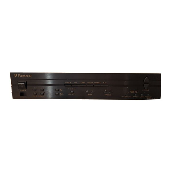
OUDNESS ARTY EMORY RESET ELECT PR-4Z 4 - Bass & Treble Controls 5 - Loudness Control 1) Source Select Buttons – Changes source input for current zone. 2 Source Indicators – Displays which source input is selected for current zone. -
Page 11: Advanced Control Function Procedures
Source changes will now be linked between all ume level etc.) to those stored in memory. The Preset func- zones. tion may be accessed at the PR-4Z front panel, PCK-IR key- pad or through an IR receiver. 1) Select zone using the Zone Select buttons (Figure 11). -
Page 12: Peripheral Devices
Each of the PR-4Z’s zones can be remotely operated by use power supplied to the keypad will have less resistance. By of the keypad (1-4) ports located on the rear of the PR-4Z. grounding the Green/White and Orange/White lines at the... -
Page 13: Pck Control Features
PRESET ON/OFF SYSTEM SYSTEM PR-4Z SYSTEM CONTROLLER Wire Infra-Red receivers as shown in Figure 15 using 22-24 AWG 1 pair twisted wire with shield. Wiring configuration 1) Bass / Volume / Treble Select Indicators – Indicates also applies to other manufacturers’ programmable keypads. -
Page 14: Spg & Ptm-1 Paging Modules
“Front Door” etc.). Call Russound for availability. operation. Use 22-24 AWG twisted pair shielded wire to con- nect the SPG to the PR-4Z page input as shown in Figure 19 Figure 20 – PTM-1 Wiring Configuration Figure 22 – PTM-1 Settings... -
Page 15: Pr-4Z Ir Emitter Outputs
Figure 24 – Common Infra-Red Output Connections Using #847 Connecting Block as an Emitter Expander The PR-4Z has 5 IR emitter outputs located on the rear CMN 1 panel: Zone 1, Zone 2, Zone 3, Zone 4 and Common. The... -
Page 16: Prc-1 Remote Control
1000 Audio and Video components, including Press the PR-4Z (AUX) and MUTE buttons simultaneously to the PR-4Z. Set it up by simply punching in a three digit code get the SET prompt. Point the remote toward the PR-4Z and number that matches your equipment. -
Page 17: Multiple Controllers
ONTROLLERS The Unit interface connections on the rear of the PR-4Z provide connections required for multiple unit interaction (4 PR-4Zs max.). The interface connections will link any multi-zone function such as ALL ON, ALL OFF, PAGING, and PARTY MODES so that these functions can be used system-wide with multiple PR-4Zs. -
Page 18: Technical Information
Dimensions: 17” W x 12” D x 3.6” H. Weight: 12 lbs. The PR-4Z complies with the requirements of the standards for Audio Video Products and Accessories (UL 1492, 1st Edition) and Radio, Television, and Electronic Apparatus (CSA C22.2 No. 1-M94). -
Page 19: Warranty
ARRANTY The Russound PR-4Z is fully guaranteed for two (2) years from the date of purchase against all defects in materials and work- manship. During this period, Russound will replace any defective parts and correct any defect in workmanship without charge for either parts or labor. - Page 20 OTES...
- Page 21 D I S T R I B U T I O N & C O N T R O L S Y S T E M S 5 Forbes Rd. Newmarket, NH 03857 603.659.5170 • Fax 603.659.5388 e-mail: tech@russound.com Fax-On-Demand: 603.659.5590 Come visit us at: 28-0071 R5...
- Page 22 PR-4Z TESTING PROCEDURE The purpose of this Test Procedure is to instruct both the Russound Test Department and any outside Service Technician.
- Page 23 01/21/99 NOTE: Before testing the PR-4Z Multi-Channel Preamp, it is required that the tester has a full working knowledge of the PR-4Z and its operation. The PR-4Z instruction manual is required reading material before testing. From the PR-4Z front panel, perform the following tests.
- Page 24 9) Sources Connect a CD player to the Source 1 input, an amplifier to the Zone 1 output and speakers to the amplifier output. Put Zone 1 on to Source 1 (Tuner). The CD should be playing through the speakers. Listen to the left and right source inputs independently, then together.
- Page 25 Press the Party button; both of the Party LEDs will turn off and the PR-4Z should return to normal operation. 19) Infra-Red Outputs...
- Page 26 Connect an 845 micro emitter to the zone 1 IR output on the rear of the PR-4Z, and to the IR window of an IR controllable device such as the CD player used in the above steps. Using a remote control which is programmed with the devices codes, aim the remote at the keypad and control the device through the PR-4Z.
- Page 27 25) Unit-to Unit Interaction Connect a second PR-4Z which will accept 3 Prong male AC input to the Female 3 prong AC outlet on the PR-4Z with the 3 prong adapter cable. Press the ALL OFF button twice and the second PR-4Z should turn off. Connect each PR-4Z into the power strip independently of each other.
- Page 28 Press the Party mode button twice on one of the PR-4Zs; both PR-4Zs should now return to normal operation. With the PR-4ZPG paging module connected to the zone 1 page input of one of the PR-4Zs, initiate a page. The page should be heard in all zones on both PR-4Zs other than the zone where the page originated.
- Page 29 28) Ground Test Disconnect power, any accessories and/or additional PR-4Zs from the unit being tested. With the cover removed, test continuity from the ground terminal of the power input connector to the following points: ground terminal of the 3 prong AC outlet ground lug on the power supply chassis main ground screw chassis...
- Page 31 PR-4Z Rear PCB.sch-1 - Wed Feb 07 15:44:38 2001...
- Page 32 * Multi-Level Explosion By Parent Part Identifier * Parent Part Identifier Range: PR-4Z - PR-4Z, Effective: 2/8/2001 Part Identifier Description Effectivity Quantity ECN # PR-4Z 4 ZONE 6 SRCE A/V PREAMP 07-0101 SM PH PN 6 X 1/4 T-A BLK 6/9/1999 8.000000...
- Page 33 * Multi-Level Explosion By Parent Part Identifier * Parent Part Identifier Range: PR-4Z - PR-4Z, Effective: 2/8/2001 Part Identifier Description Effectivity Quantity ECN # 01-0077 PCB PREAMP MAIN 12/27/1995 1.000000 02-0001 RES 1/4W 5% 3.3 K 7/2/1996 4.000000 02-0002 RES 1/4W 5% 560 OHM 12/27/1995 26.000000...
Need help?
Do you have a question about the PR-4Z and is the answer not in the manual?
Questions and answers