Table of Contents
Advertisement
Available languages
Available languages
Advertisement
Table of Contents

Subscribe to Our Youtube Channel
Related Manuals for DFI LANPARTY UT X58 t3eh8


Summary of Contents for DFI LANPARTY UT X58 t3eh8
-
Page 1: System Board
System Board User’s Manual 935-UX5831-000G 08300848E... -
Page 2: Fcc And Doc Statement On Class B
Copyright This publication contains information that is protected by copyright. No part of it may be reproduced in any form or by any means or used to make any transfor- mation/adaptation without the prior written permission from the copyright hold- ers. -
Page 3: Table Of Contents
Table of Contents About this Manual................Warranty....................Static Electricity Precaution..............Safety Measures..................About the Package................Before Using the System Board............System Board Layout................English..................... Français....................Deutsch....................Italiano....................Español....................Debug LED POST and Troubleshooting ........ -
Page 4: About This Manual
(Main Board Utility CD) will appear. Click the “TOOLS” icon then click “Manual” on the main menu. For additional information on the system board, please download the complete version of the manual from DFI’s website. Visit www.dfi.com. Warranty 1. -
Page 5: Static Electricity Precaution
Introduction Static Electricity Precautions It is quite easy to inadvertently damage your PC, system board, components or devices even before installing them in your system unit. Static electrical discharge can damage computer components without causing any signs of physical damage. You must take extra care in handling them to ensure against electrostatic build-up. -
Page 6: About The Package
Introduction About the Package The system board package contains the following items. If any of these items are missing or damaged, please contact your dealer or sales representative for assistance. One system board One Bernstein audio module with cable One Flame-Freezer heatsink kit One IDE round cable One floppy round cable Four Serial ATA data cables... -
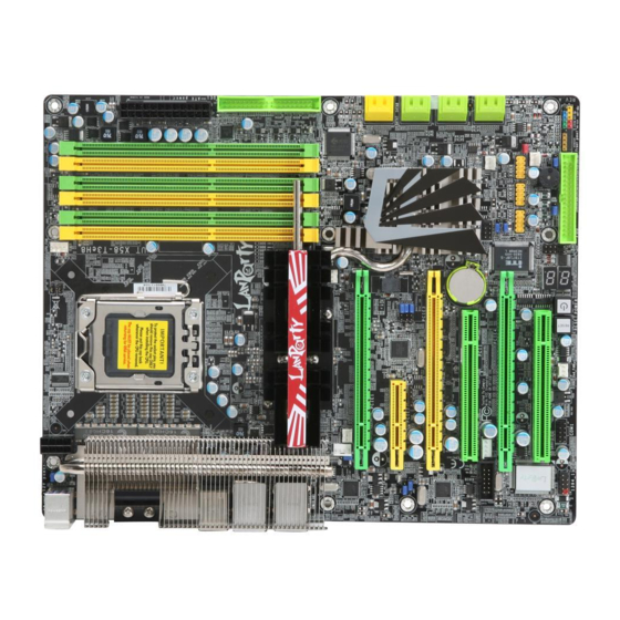
Page 7: System Board Layout
Introduction System Board Layout 12V power CPU fan DRAM Power LED DIMM 2 DIMM 4 DIMM 6 Mouse PS/2 power DIMM 5 DIMM 1 DIMM 3 select (J ) power 1394-0 USB 8-9 LAN 1 USB 10-11 LAN 2 Intel USB 6-7 5V/12V power... -
Page 8: English
English Chapter 1 - Specifications Processor • LGA 1366 socket for Intel Core i7 processors ® • Intel QuickPath Interconnect (QPI) technology - point-to-point ® interface that connects to X58; providing a dynamically scalable interconnect for increased bandwidth, lower latency and stability •... - Page 9 English • Mar vell 88E8052 and Mar vell 88E8053 PCIE Gigabit LAN controllers with Teaming technology • Fully compliant to IEEE 802.3 (10BASE-T), 802.3u (100BASE- TX) and 802.3ab (1000BASE-T) standards Storage • Intel ICH10R chip - Intel Matrix Storage technology - Supports up to 6 SATA devices - SATA speed up to 3Gb/s - RAID 0, RAID 1, RAID 0+1 and RAID 5...
-
Page 10: Jumper Settings
English Chapter 2 - Hardware Installation Jumper Settings Clear CMOS Data Clearing CMOS Data using JP2 Intel ICH9R 1-2 On: Normal 2-3 On: (default) Clear CMOS Data If you encounter the following, a) CMOS data becomes corrupted. b) You forgot the supervisor or user password. c) The overclocked settings in the BIOS resulted to the system’s in- stability or caused system boot up problems. - Page 11 English ® Clearing CMOS Data using the EZ Clear Function ® EZ Clear bypasses the manual process of using a jumper to clear the CMOS by simply using the reset and power buttons. Important: ® EZ Clear is supported only if standby power is present in the system.
-
Page 12: Usb Power Select
English PS/2 Power Select 1-2 On: 5V 2-3 On: (default) 5VSB Important: The 5VSB power source of your power supply must suppor t ≥720mA. Intel ICH9R Selecting 5VSB will allow you to use the PS/2 keyboard or PS/2 mouse to wake up the system. USB Power Select USB 6-11 (JP5) - Page 13 English Speaker On/Off Select Intel ICH9R Buzzer 2-3 On: 1-2 On: Speaker Off Speaker On (default) The system board is equipped with a buzzer which serves as the PC’s speaker. By default the buzzer is “on” allowing you to hear the system’s beep messages and warnings.
- Page 14 English Safe Boot Intel ICH9R 1-2 On: 2-3 On: Default Safe boot This jumper is used to safely reboot the system whenever the sys- tem hangs and you are unable to restart the system. 1. Power-off the system then unplug the power cord. 2.
-
Page 15: Secondary Rtc Reset
English Secondary RTC Reset Intel ICH9R JP12 1-2 On: Normal 2-3 On: (default) RTC reset When the RTC batter y is removed, this jumper resets the manageability register bits in the RTC. Note: 1. The SRTCRST# input must always be high when all other RTC power planes are on. - Page 16 English CPU FSB Select JP13 Intel JP14 ICH9R JP15 By default, JP13 to JP15 are set to pins 1 and 2 On. This setting will allow the system to automatically run according to the CPU’s FSB. If you want to change the setting, please refer to the table below. By CPU FSB 800 FSB 1066...
- Page 17 English CPU_VTT Select JP26 1-2 On 2-3 On Intel ICH9R JP27 1-2 On 2-3 On JP26 and JP27 are used to select the CPU’s voltage. JP26 JP27 CPU_VTT 1.2V (default) 1-2 On 1-2 On 2-3 On 2-3 On 1.4V 1.6V 2-3 On 1-2 On...
- Page 18 English Rear Panel I/O Ports LAN 1 LAN 2 PS/2 Mouse 1394-0 PS/2 K/B USB 8-9 USB 10-11 USB 6-7 PS/2 Ports and IEEE 1394 Ports PS/2 Mouse PS/2 KB 1394-0 Intel ICH9R 1394-1 PS/2 Mouse and PS/2 Keyboard Ports These ports are used to connect a PS/2 mouse and a PS/2 key- board.
- Page 19 English at the rear of the system chassis then connect the 1394 port cable to this connector. USB Ports and LAN Ports USB 9 USB 8 LAN 1 USB 11 USB 10 Intel ICH9R LAN 2 USB 7 USB 6 USB 4-5 USB 0-1 USB 2-3...
- Page 20 English Bernstein Audio Module Left audio channel Line-in Ground Ground Line-out Right audio channel Mic-in Center/ CD-in Subwoofer Rear R/L Side R/L 1 0 9 Line out Jet Detect Line out_Left S/PDIF-out Sense N. C. Line out_Right Mic Jet Detect S/PDIF-in Mic_Right Mic_Left...
- Page 21 English Coaxial RCA S/PDIF-in and SPDIF-out Jacks These jacks are used to connect external audio output devices using coaxial S/PDIF cables. CD-in Connector The CD-in connector is used to receive audio from a CD-ROM drive, TV tuner or MPEG card. Front Audio Connector The front audio connector is used to connect to the line-out and mic-in jacks that are at the front panel of your system.
-
Page 22: Serial Ata Connectors
English 3. The length of the audio cable pro- vides the option and flexibility of in- stalling the module on any available expansion bracket slot at the rear of the system chassis. Remove the screw of the bracket where you want the audio module installed then remove the bracket. - Page 23 English Floppy Disk Drive Connector and IDE Connector Intel ICH9R Floppy Disk Drive Connector The floppy disk drive connector is used to connect a floppy drive. Insert one end of the floppy cable into this connector and the other end-most connector to the floppy drive. The colored edge of the cable should align with pin 1 of this connector.
- Page 24 English IrDA, CIR and Serial (COM) Connectors CIRTX IRTX Ground Ground Intel ICH9R CIRRX IRRX N. C. N. C. 5VSB IrDA CIR IrDA and CIR Connectors These connectors are used to connect an IrDA module and/or CIR module. Note: The sequence of the pin functions on some IrDA/CIR cable may be reversed from the pin function defined on the system board.
-
Page 25: Cooling Fan Connectors
English Cooling Fan Connectors Ground Power Sense N. C. Ground Speed Power Control CPU fan Fan 3 Power Ground N. C. Power Ground N. C. System fan Intel NB fan ICH9R Power Ground N. C. Ground N. C. Power 1st fan 2nd fan These fan connectors are used to connect cooling fans. - Page 26 English EZ Touch Switches Intel ICH9R Reset Power The presence of the power switch and reset switch on the system board are user-friendly especially to DIY users. They provide conven- ience in powering on and/or resetting the system while fine tuning the system board before it is installed into the system chassis.
- Page 27 English LEDs DRAM Power LED Standby Intel Power LED ICH9R Diagnostic DRAM Power LED This LED will light when the system’s power is on. Standby Power LED This LED will light when the system is in the standby mode. Diagnostic LED The Diagnostic LED displays POST codes.
-
Page 28: Power Connectors
English Power Connectors Use a power supply that complies with the ATX12V Power Supply Design Guide Version 1.1. An ATX12V power supply unit has a standard 24-pin ATX main power connector that must be inserted into this connector. 1 2 2 4 +3.3VDC +12VDC +5VDC... - Page 29 English The power connectors from the power supply unit are designed to fit the 24-pin and 8-pin connectors in only one orientation. Make sure to find the proper orientation before plugging the connectors. The FDD-type power connectors are additional power connector.s If you are using more than one graphics cards, we recommend that you plug power cables from your power supply unit to the 5V/12V power connectors.
- Page 30 English Restarting the PC Normally, you can power-off the PC by: 1. Pressing the power button at the front panel of the chassis. 2. Pressing the power switch that is on the system board (note: not all system boards come with this switch). If for some reasons you need to totally cut off the power supplied to the PC, switch off the power supply or unplug the power cord.
-
Page 31: Front Panel Connectors
English Front Panel Connectors Intel ICH9R RESET SPEAKER HD-LED PWR-LED ATX-SW HD-LED: Primary/Secondary IDE LED This LED will light when the hard drive is being accessed. RESET: Reset Switch This switch allows you to reboot without having to power off the system thus prolonging the life of the power supply or system. - Page 32 English Note: If a system did not boot-up and the Power/Standby LED did not light after it was powered-on, it may indicate that the CPU or memory module was not installed properly. Please make sure they are properly inserted into their corresponding socket. Pin Assignment HD-LED HDD LED Power...
-
Page 33: Pci Express Slots
English PCI Express Slots PCIE 1 PCIE 2 Intel ICH9R PCIE 3 PCIE 4 PCI Express x16 Install PCI Express x16 graphics card, that comply to the PCI Ex- press specifications, into the PCI Express x16 slot. To install a graph- ics card into the x16 slot, align the graphics card above the slot then press it down firmly until it is completely seated in the slot. - Page 34 English Smart Connectors The Smart Connectors (USB, IEEE 1394 and Front Panel) serve as extended connectors allowing you to easily connect cables to the connectors that are on the system board. This is specially advantageous when using the front panel connectors as this will prevent wrong cable connection.
-
Page 35: Raid Levels
English Chapter 3 - RAID The Intel ICH10R chip alows configuring RAID on Serial ATA drives connected to SATA 1 to SATA 6. It supports RAID 0, RAID 1, RAID 0+1 and RAID 5. The JMicron JMB363 chip allows configuring RAID on another 2 Se- rial ATA drives connected to SATA 7 and SATA 8. - Page 36 English Settings To enable the RAID function, the following settings are required. 1. Connect the Serial ATA drives. 2. Configure Serial ATA in the Award BIOS. 3. Configure RAID in the RAID BIOS. 4. Install the RAID driver during OS installation. 5.
- Page 37 Step 5: Install the Intel Matrix Storage Manager Step 6: Install the JMB36X Driver For steps 5 and 6, refer to the complete version of the manual for steps on installing the utlity and driver. Please download the manual from DFI’s website. Visit www.dfi.com.
-
Page 38: Français
Français Chapitre 1 - Spécifications Processeur • Interface de connexion LGA 1366 pour processeurs Intel ® Core • Technologie Intel QuickPath Interconnect (QPI) – Interface de ® point à point qui se connecte au X58, appor tant une interconnexion dynamiquement extensible pour l’obtention d’une plus grande bande passante, plus de stabilité... - Page 39 Français • Marvell 88E8052 et Marvell 88E8053 PCIE Gigabit LAN • Entièrement conforme IEEE 802.3 (10BASE-T), 802.3u (100BASE-TX) et 802.3ab (1000BASE-T) standard Stockage • Intel ICH10R Chipset - Technologie de Intel Matrix Storage - 6 dispositifs de SATA - SATA allant jusqu’à 3Gb/s - RAID 0, RAID 1 RAID 0+1 et RAID 5 •...
- Page 40 Français Chapitre 2 - Installation de Matériel Cavalier Effacer les Données CMOS Effacement des Données CMOS en Utilisant JP2 Intel ICH9R 1-2 On: Normal 2-3 On: (default) Clear CMOS Data Si vous rencontrez les éléments suivants, a) Données CMOS devenant corrompues b) Vous avez oublié...
- Page 41 Français ® Effacement des Données CMOS en Utilisant la Fonctionnalité EZ Clear ® EZ Clear contourne le processus manuel d’utilisation d’un cavalier pour effacer CMOS en utilisant simplement les boutons de réinitialisation et d’alimentation. Important: EZ Clear ® n’est supportée que si l’alimentation de veille est présente sur le système.
- Page 42 Français Sélectionner l’alimentation PS/2 1-2 On: 5V 2-3 On: (default) 5VSB Important: La source d’alimentation 5VSB de votre alimentation doit suppor tée ≥720mA. Intel ICH9R En sélectionnant 5VSB, vous pourrez utiliser le clavier PS/2 ou la souris PS/2 pour “réveiller” le système. Sélectionner l’alimentation USB USB 6-11 (JP5)
- Page 43 Français Sélection des Haut-parleurs ON/OFF Intel ICH9R Buzzer 2-3 On: 1-2 On: Speaker Off Speaker On (default) La carte système est équipée d’un avertisseur sonore qui sert en tant que haut-parleur du PC. Par défaut l’avertisseur sonore est « ON » permettant d’entendre les « bips » des messages et les aver tissements.
- Page 44 Français Amorce Sécurisée Intel ICH9R 1-2 On: 2-3 On: Default Safe boot Ce cavalier est utilisé pour rebooter le système en toute sécurité quand il se bloque ou que vous ne réussissez pas à le redémarrer. 1. Débrancher le système et retirer le cordon d’alimentation. 2.
- Page 45 Français Réinitialisation de l’horloge Temps Réel Secondaire Intel ICH9R JP12 1-2 On: Normal 2-3 On: (default) RTC reset Lorsque la pile de l’horloge est enlevée, ce cavalier réinitialise la capacité de gestion des octets du registre de l’horloge. Note: L’entrée SRTCRST# doit toujours être élevée lorsque toutes les autres couches Power plane de l’horloge sont ON.
- Page 46 Français Sélectionner le FSB du Processeur. JP13 Intel JP14 ICH9R JP15 Par défaut, les trois cavaliers sont tous réglés avec les broches 1 et 2 On.Ce réglage permettra au système de fonctionner automatiquement en fonction du FSB du processeur. Si vous désirez modifier le réglage, veuillez vous référer au tableau ci-dessous.
- Page 47 Français Sélectionner le CPU_VTT JP26 1-2 On 2-3 On Intel ICH9R JP27 1-2 On 2-3 On JP26 JP27 CPU_VTT 1-2 On 1-2 On 1.2V (default) 1.4V 2-3 On 2-3 On 2-3 On 1-2 On 1.6V...
- Page 48 Français Ports I/O de l’arrière du Panneau LAN 1 LAN 2 PS/2 Mouse 1394-0 PS/2 K/B USB 8-9 USB 10-11 USB 6-7 Ports PS/2 et IEEE 1394 PS/2 Mouse PS/2 KB 1394-0 Intel ICH9R 1394-1 Ports Souris PS/2 et Clavier PS/2 Ces ports sont utilisés pour raccorder une souris PS/2 et un clavier PS/2.
- Page 49 Français le support encartable dans une fente disponible à l’arrière du châssis du système et raccorder la câble du port 1394 à ce connecteur. Ports USB et LAN USB 9 USB 8 LAN 1 USB 11 USB 10 Intel ICH9R LAN 2 USB 7 USB 6...
- Page 50 Français Module Audio Bernstein Left audio channel Line-in Ground Ground Line-out Right audio channel Mic-in Center/ CD-in Subwoofer Rear R/L Side R/L 1 0 9 Line out Jet Detect Line out_Left S/PDIF-out Sense N. C. Line out_Right Mic Jet Detect S/PDIF-in Mic_Right Mic_Left...
- Page 51 Français Prise de côté gauche/droite (grise) Cette prise est utilisée pour se connecter aux haut-parleurs de côté droits et gauches du système audio. Prises coaxiales d’entrée RCA S/PDIF et de sortie SPDIF Ces prises sont utilisées pour connecter les appareils de sortie audio externes en utilisant les câbles coaxiaux S/PDIF.
- Page 52 Français 2 Insérer une extrémité du câble sur le connecteur Audio Bernstein sur la car te système et l’autre connecteur correspondant sur le module audio. Intel ICH9R Bernstein audio module connector Connecteur module Audio Bernstein 3. La longueur du câble audio donne la possibilité...
- Page 53 Français Connecteurs I/O Les Connecteurs en Série ATA SATA 7-8 Intel SATA 1-2 ICH9R SATA 3-4 SATA 5-6 Les connecteurs en série ATA (SATA) sont utilisés pour raccorder les disques durs ATA en série. Relier une extrémité du câble en série ATA au connecteur en série ATA et l’autre extrémité...
- Page 54 Français Connecteur de Lecteur de Disquettes et Connecteur IDE Intel ICH9R Connecteur de Lecteur de Disquettes Le connecteur de lecteur de disquettes est utilisé pour raccorder le lecteur de disquettes. Il possède un mécanisme d’insertion qui empêche sa mauvaise installation. Insérer une extrémité du câble du lecteur de disquette dans ce connecteur et l’autre dans le lecteur de disquette.
- Page 55 Français Connecteurs IrDA, CIR et en Série (COM) CIRTX IRTX Ground Ground Intel ICH9R CIRRX IRRX N. C. N. C. 5VSB IrDA CIR Connecteurs IrDA et CIR .Ces connecteurs sont utilisés pour raccorder le module IrDA ou/et le module CIR. Note: La séquence de la fonction des broches (signal) sur certains câbles IrDA/CIR peut être inversée à...
- Page 56 Français sur un support encartable. Installer le support encartable dans une fente disponible à l’arrière du châssis du système et raccorder le câble du port en série à ce connecteur. Le bord coloré du câble devrait être aligné avec l’ergot 1 de ce connecteur. Connecteurs de Ventilateur de Refroidissement Ground Power...
- Page 57 Français Commutateurs à Touche EZ Intel ICH9R Reset Power La présence des commutateurs d’alimentation et de réinitialisation sur la carte système est conviviale et particulièrement pour les utilisateurs étant bricoleurs. Ils sont très pratiques pour allumer ou réinitialiser le système tout en ajustant la car te système avant l’installation sur le châssis.
- Page 58 Français Voyants DEL DRAM Power LED Standby Intel Power LED ICH9R Diagnostic Voyant DEL d’alimentation DRAM Ce voyant DEL s’allumera lorsque le système est allumé. Voyant DEL d’alimentation à l’état de Veille Ce voyant DEL s’allumera lorsque le système est en mode veille. Voyant DEL de Diagnostic Le voyant DEL de diagnostic affiche les codes POST.
- Page 59 Français Connecteurs d’alimentation Utiliser une alimentation électrique conforme à la version 1.1 du guide d’alimentation électrique ATX12V. Une unité d’alimentation électrique ATX12V possède un connecteur d’alimentation principale ATX à 24 broches qui doit être inséré dans ce connecteur. 1 2 2 4 +3.3VDC +12VDC +5VDC...
- Page 60 Français Les connecteurs d’alimentation de l’unité d’alimentation électrique sont conçus pour s’adapter aux connecteurs à 24 et 8 broches seulement dans une direction. S’assurer d’observer la bonne orienta- tion avant de brancher les connecteurs. Les connecteurs d’alimentation de type FDD sont des connecteurs supplémentaires d’alimentation.
- Page 61 Français Redémarrage du PC Normalement vous pouvez éteindre le PC en : 1. Appuyant sur le bouton d’alimentation sur le panneau frontal du chassis. 2. En appuyant sur le commutateur d’alimentation se trouvant sur la carte système (note : toutes les cartes systèmes ne possèdent pas ce commutateur) Si, pour quelque raison que ce soit, vous devez éteindre l’alimentation du PC, éteindre l’alimentation ou débrancher le cordon d’alimentation.
- Page 62 Français Connecteurs Frontaux du Panneau Intel ICH9R RESET SPEAKER HD-LED PWR-LED ATX-SW HD-LED: Voyant DEL IDE Principal/Secondaire Ce voyant DEL s’allumera lorsqu’on accède au disque dur. RESET: Commutateur de Réinitialisation Ce commutateur vous permet de redémarrer sans avoir à éteindre le système et par conséquent en permettant une durée de vie de l’alimentation ou du système prolongée.
- Page 63 Français PWR-LED: Voyant DEL d’alimentation / état de veille Ce voyant DEL s’allumera lorsque le système est allumé. Lorsque le système est sur le statut S1 (POS – alimentation suspendue) ou S3 (STR – suspendue dans la RAM), il clignotera toutes les secondes. Note: Si le système n’a pas démarré...
- Page 64 Français Fentes PCI Express PCIE 1 PCIE 2 Intel ICH9R PCIE 3 PCIE 4 PCI Express x16 Installer la carte graphique PCI Express X 16 se conformant aux spécifications PCI Express dans la fente X 16 du PCI Express. Pour installer une carte graphique dans la fente x16, aligner la car te graphique au-dessus de la fente et appuyer vers le bas fermement jusqu’à...
- Page 65 Français Connecteurs Smart Les connecteurs Smart (USB, IEEE 1394 et panneau avant) servent de rallonge de connecteurs vous permettant de facilement raccorder des câbles aux connecteurs se trouvant sur la car te mère. Ceci est par ticulièrement utile aux connecteurs du panneau avant car cela empêchera le raccordement de câbles ne convenant pas.
- Page 66 Français Chapitre 3 - RAID La puce Intel ICH10R permet la configuration RAID sur les lecteurs Série ATA connectés du SATA 1 au SATA 6. Elle suppor te les systèmes RAID 0, RAID 1, RAID 0+1 et RAID 5. La puce JMicron JMB363 permet la configuration RAID sur deux autres lecteurs Série Serial ATA connectés à...
- Page 67 Français RAID 5 RAID 5 répar tit en écriture les données et les informations concernant la parité sur les disques durs. Il est insensible aux défaillances et permet d’obtenir de bien meilleures performances des disques durs ainsi qu’une capacité de stockage accrue. Réglages Pour activer la fonctionnalité...
- Page 68 Français Etape 3 : Configurer le système RAID dans le BIOS RAID Configurer le système RAID dans le BIOS RAID Intel. Lorsque le système démarre et que tous les disques durs ont été détectés, le message de statut du BIOS Intel apparaîtra. Appuyer sur la touche <Ctrl>+<I>...
- Page 69 Etape 5: Installer le Intel Matrix Storage Manager Etape 6: Installer le driver de JMB36X Se référer à la version complète du manuel pour les étapes d’installation du progiciel et du pilote. Veuillez télécharger le manuel depuis le site Web de DFI: www.DFI.com.
-
Page 70: Deutsch
Deutsch Kapitel 1 - Spezifikation Prozessor • LGA 1366 Steckplatz für Intel Core i7 Prozessoren ® • Intel® QuickPath Interconnect (QPI) Technology - Point-to-Point Schnittstelle zum Anschluss an X58; bietet eine dynamische skalierbare Verbindung für verbesser te Bandbreite, geringere Latenz und Stabilität •... - Page 71 Deutsch Lagerung • Intel ICH10R chip - Intel Matrix Storage technologie - 6 SATA-Vorrichtungen - SATA bis zu 3Gb/s schnell - RAID 0, RAID 1, RAID 0+1 und RAID 5 • JMicron JMB363 PCI Express und SATA und PATA - Unterstützung der Festplatten bis zum UltraDMA 100Mbps - 2 SATA-Vorrichtungen - SATA bis zu 3Gb/s schnell - RAID 0 und RAID 1...
- Page 72 Deutsch Kapitel 2 - Installieren des Hardware Jumper Löschen der CMOS Daten Löschen der CMOS Daten unter Verwendung von JP2 Intel ICH9R 1-2 On: Normal 2-3 On: (default) Clear CMOS Data Sollten Sie eins der folgenden Probleme haben, a) die CMOS Daten sind beschädigt. b) Sie haben das Supervisor oder User Passwort vergessen.
- Page 73 Deutsch 3. Verbinden Sie nun wieder den Netzstecker und schalten Sie das System ein. ® Löschen der CMOS Daten unter Verwendung der EZ Clear Funktion ® EZ Clear umgeht den manuellen Prozess des Setzens der Jumper zum Löschen des CMOS durch einfache Betätigung der Reset- und Power-Schalter.
- Page 74 Deutsch PS/2 Power Wählen Sie 1-2 On: 5V 2-3 On: (default) 5VSB Wichtig: 5VSB Stromquelle Ihres Netzteils muss ≥720mA unterstützen. Intel ICH9R Die Auswahl von 5VSB erlaubt es Ihnen, Ihr System per PS/2 Key- board oder PS/2 Maus aufzuwecken. USB Power Wählen Sie USB 6-11 (JP5) 1-2 On: 5V...
- Page 75 Deutsch Speaker On/Off Auswahl Intel ICH9R Buzzer 2-3 On: 1-2 On: Speaker Off Speaker On (default) Das Systemboard ist mit einem Summer ausgestattet, der als Lautsprecher des PC’s dient. Ab Werk ist die Standardeinstellung des Summers “on” wodurch Sie die Warnungen und Piep-Nachrichten des Systems hören.
- Page 76 Deutsch Zulässiger Start Intel ICH9R 1-2 On: 2-3 On: Default Safe boot Brücke ist benutzt, um das System zulässig neu zustarten, wenn das System hängt und Sie das System nicht neu starten können. 1. Schalten Sie das System aus und ziehen Sie den Netzstecker. 2.
- Page 77 Deutsch Sekundären RTC-Reset Intel ICH9R JP12 1-2 On: Normal 2-3 On: (default) RTC reset Wird die RTC-Batterie entfernt, setzt diese Steckbrücke die Handhabbarkeit der Registerbits der RTC zurück. Hinweis: 1. Der SRTCRST# Input muss immer hoch sein, wenn alle anderen RTC Versorgungslagen laufen. 2.
- Page 78 Deutsch CPU-FSB wählen Sie JP13 Intel JP14 ICH9R JP15 Standardmäßig sind alle drei Steckbrücken auf die Pins 1 und 2 gesetzt. Auf diese Weise läuft das System entsprechend dem Frontside Bus der CPU. Falls Sie die Einstellungen ändern wollen, finden Sie Informationen in der folgenden Tabelle. By CPU FSB 1333 FSB 800...
- Page 79 Deutsch CPU_VTT wählen Sie JP26 1-2 On 2-3 On Intel ICH9R JP27 1-2 On 2-3 On JP26 JP27 CPU_VTT 1-2 On 1-2 On 1.2V (default) 2-3 On 2-3 On 1.4V 2-3 On 1-2 On 1.6V...
- Page 80 Deutsch Rückseite I/O Ports LAN 1 LAN 2 PS/2 Mouse 1394-0 PS/2 K/B USB 8-9 USB 10-11 USB 6-7 PS/2 Ports und IEEE 1394 Ports PS/2 Mouse PS/2 KB 1394-0 Intel ICH9R 1394-1 PS/2 Maus und PS/2 Keyboard Ports Diese Ports werden zum Anschluss von PS/2 Maus und PS/2 Key- board verwendet.
- Page 81 Deutsch Installieren Sie das Blech in eine verfügbare Halterung an der Rückseite des Gehäuses und verbinden Sie das Kabel des 1394 Ports mit dem entsprechenden Anschluss. USB Ports und LAN Ports USB 9 USB 8 LAN 1 USB 11 USB 10 Intel ICH9R LAN 2...
- Page 82 Deutsch Bernstein Audio-Modul Left audio channel Line-in Ground Ground Line-out Right audio channel Mic-in Center/ CD-in Subwoofer Rear R/L Side R/L 1 0 9 Line out Jet Detect Line out_Left S/PDIF-out Sense N. C. Line out_Right Mic Jet Detect S/PDIF-in Mic_Right Mic_Left Side view...
- Page 83 Deutsch Mic-in Stecker (Pink) Mit diesem Stecker verbinden Sie ein externes Mikrophon mit dem System. Coaxial RCA S/PDIF-in und SPDIF-out Stecker Mit diesen Steckern verbinden Sie externe Audioausgabegeräte die koaxiale S/PDIF Kabel verwenden. CD-in Anschluss Der CD-in Anschluss wird verwendet, um Audio von einem CD- ROM Laufwerk, einer TV Tuner oder MPEG-Karte zu empfangen.
- Page 84 Deutsch 2. Verbinden Sie das eine Ende des Audiokabels mit dem Bernstein Audioanschluss auf dem Systemboard und das andere Ende mit dem e n t s p r e c h e n d e n Intel Anschluss auf dem ICH9R Audiomodul.
- Page 85 Deutsch I/O Anschlüsse Serial ATA Anschlüsse SATA 7-8 Intel SATA 1-2 ICH9R SATA 3-4 SATA 5-6 Über die Serial ATA (SATA) Anschlüsse werden Serial ATA Laufwerke angeschlossen. Verbinden Sie das eine Ende des Serial ATA Kabels mit dem Serial ATA Anschluss und das andere Ende mit Ihrem Serial ATA Gerät.
- Page 86 Deutsch Floppy Disk Drive Anschluss und IDE Anschluss Intel ICH9R Floppy Disk Drive Anschluss Über den Floppy Disk Drive Anschluss werden Floppy-Laufwerke angeschlossen. Er verfügt über einen Verbindungsmechanismus der eine Fehlinstallation vermeidet. Verbinden Sie ein Ende des Floppy- Kabels mit dem Anschluss auf dem Board und das andere Ende mit dem Floppy-Laufwerk.
- Page 87 Deutsch IrDA, CIR und Serial (COM) Anschlüsse CIRTX IRTX Ground Ground Intel ICH9R CIRRX IRRX N. C. N. C. 5VSB IrDA CIR IrDA und CIR Anschlüsse Über diese Anschlüsse werden IrDA Module und/oder CIR Module angeschlossen. Bitte beachten: Die Anordnung der PIN-Funktionen kann bei einigen IrDA/CIR Kabeln abweichend von der Anordnung auf dem Systemboard sein.
- Page 88 Deutsch sein. Installieren Sie das Blech in eine verfügbare Halterung an der Rückseite des Gehäuses und verbinden Sie das Kabel des seriellen Ports mit dem entsprechenden Anschluss. Das farblich markier te Ende des Kabels muss mit Pin 1 des Anschlusses in Übereinstimmung gebracht werden.
- Page 89 Deutsch EZ Touch Schalter Intel ICH9R Reset Power Das Vorhandensein von Power- und Reset-Schaltern auf dem Systemboard ist speziell für DIY-User sehr anwenderfreundlich. Sie bieten die Möglichkeit bequem das System ein-/auszuschalten und einen Reset durchzuführen und somit die Einstellungen des Systemboards zu verfeinern bevor es in ein Gehäuse eingebaut wird.
- Page 90 Deutsch LEDs DRAM Power LED Standby Intel Power LED ICH9R Diagnostic DRAM Power LED Diese LED leuchtet wenn das System eingeschaltet ist. Standby Power LED Diese LED leuchtet wenn das System im Standby Modus ist. Diagnostic LED Die Diagnostic LED zeigt POST Codes an. POST (Power-On Self Tests), die durch das BIOS gesteuert werden, werden bei jedem Start des Systems durchgeführt.
- Page 91 Deutsch Stromanschlüsse Verwenden Sie ein Netzteil, dass den ATX12V Netzteil Designrichtlinien Version 1.1 entspricht. Ein ATX12V Netzteil verfügt über einen standard 24-Pin ATX Hauptstromanschluss. Verbinden Sie diese Stromanschlüsse. 1 2 2 4 +3.3VDC +12VDC +5VDC +12VDC +5VDC +5VDC +5VSB PWR_OK +5VDC PS_ON# +5VDC...
- Page 92 Deutsch Die Stromanschlüsse des Netzteils sind so entworfen, dass die die 24-Pin und 8-Pin Anschlüsse nur in einer Ausrichtung verbunden werden können. Stellen Sie sicher, dass die Ausrichtung korrekt ist bevor Sie die Anschlüsse verbinden. Die FDD-Typ Stromanschlüsse sind zusätzliche Stromanschlüsse. Sollten Sie mehr als eine Grafikkarte verwenden, so empfehlen wir, dass Sie die Stromkabel des Netzteils mit den 5V/12V Stromanschlüssen verbinden.
- Page 93 Deutsch Neustart des PC’s In der Regel lässt sich der PC wie folgt ausschalten: 1. Betätigung des Power-Schalters auf der Frontseite des Gehäuses. oder 2. Betätigung des Power-Schalters der sich auf dem Systemboard befindet (Anmerkung: nicht alle Systemboards verfügen über diesen Schalter).
- Page 94 Deutsch Frontanschlüsse Intel ICH9R RESET SPEAKER HD-LED PWR-LED ATX-SW HD-LED: Primäre/Sekundäre IDE LED Diese LED leuchtet auf, wenn auf die Festplatte zugegriffen wird. RESET: Reset-Schalter Dieser Schalter erlaubt es Ihnen einen Neustart durchzuführen ohne die Stromzufuhr zu unterbrechen. Dadurch wird die Lebensdauer des Netzteils und des Systems verlängert.
- Page 95 Deutsch PWR-LED: Power/Standby LED Diese LED leuchtet, wenn die Stromzufuhr des Systems eingeschaltet ist. Sollte das System sich im S1 (POS - Power On Suspend) oder S3 (STR - Suspend To RAM) Status befinden, so blinkt die LED einmal pro Sekunde. Bitte beachten: Sollte das System nicht hochfahren und die Power/Standby LED nicht aufleuchten nachdem Sie den Power-Schalter betätigt...
- Page 96 Deutsch PCI Express Steckplätze PCIE 1 PCIE 2 Intel ICH9R PCIE 3 PCIE 4 PCI Express x16 Installieren Sie eine PCI Express x16 Grafikkarte, die den PCI Express Spezifikationen entspricht in den PCI Express x16 Steckplatz. Zur Instal- lation der Grafikkarte in den x16 Steckplatz richten Sie die Grafikkarte über dem Steckplatz aus und drücken sie dann in den Steckplatz bis sie fest sitzt.
- Page 97 Deutsch Smart Connectoren Die Smart Connectoren (USB, IEEE 1394 und Front Panel) dienen als erweiterte Stecker, die ein bequemes Anschließen von Kabeln an die Buchsen der System-Platine ermöglichen. Dies ist ein besonderer Vorteil bei den Buchsen am Bedienfeld, da es hilft, falsche Kabelanschlüsse zu vermeiden.
- Page 98 Deutsch Kapitel 3 - RAID Intel ICH10R chip erlaubt Konfiguration RAID auf Serial ATA Laufwerke, welche an SATA 1 zu SATA 6 angeschlossen sind. Er unterstützt RAID 0, RAID 1, RAID 0+1 und RAID 5. JMicron JMB363 chip erlaubt Konfiguration RAID auf andere 2 Serial ATA Laufwerke, welche an SATA 7 und SATA 8 angeschlossen sind.
- Page 99 Deutsch RAID 5 RAID 5 führ t Striping von sowohl Daten- als auch Paritätsinformationen über Festplatten aus. Zu seinen Vorteilen zählen Fehler toleranz, eine bessere Festplattenleistung und höhere Speicherkapazität. Einstellungen Um die RAID-Funktion zu aktivieren sind folgende Einstellungen notwendig. 1. Schliessen Sie die Serial ATA Laufwerke an. 2.
- Page 100 Deutsch 4. Schreiben Sie <Y> und drücken dann die <Enter> Taste. 5. Führen Sie einen Neustart des Systems durch. Step 3: Konfiguration von RAID im RAID BIOS Konfigurieren Sie RAID im Intel RAID BIOS Wenn das System hochfährt und alle Laufwerke erkannt wurden erscheint die AMD BIOS Status Nachricht auf dem Bildschirm.
- Page 101 Windows Setup wie erforderlich neustarten kann. Schritt 5: Installation des Intel Matrix Storage Manager Schritt 6: Installation des JMB36X Driver Es bezieht sich auf ausführliche Version der Montageanweisung für Dienstprogramm und Treiber. Bitte download die Montageanweisung von der DFI’s Website: www.DFI.com.
-
Page 102: Italiano
Italiano Chapter 1 - Quick Guide Scheda Madre Questa guida rapida di installazione indica i passaggi principali per l’assemblaggio della scheda madre. Tutte le operazioni di assemblaggio della scheda madre richiedono che i prodotti collegati alla motherboard non siano connessi alla rete elettrica. - Page 103 Italiano Una volta inseriti processori e DIMM è possibile procede all’assemblaggio del prodotto in un apposito contenitore denominato cabinet. Fare riferimento alla documentazione del cabinet per un corretto assemblaggio. Fare attenzione che tutti i distanziali per evitare il contatto accidentale della scheda madre con le parti del cabinet e le viti di fissaggio siano correttamente montate.
- Page 104 Italiano Esempi di Disposizione Mouse Parallela Firewire Ethernet Line-in Altoparlanti Microfono Tastiera VGA Analogica VGA Digitale...
- Page 105 Italiano Capitolo 2 - Introduzione Specifiche Processore • Socket LGA 1366 per processori Intel Core ® • Tecnologia Intel QuickPath Interconnect (QPI) – interfaccia da ® punto a punto che si collega con X58; fornisce così un’interconnessione dinamicamente scalabile per un aumento della larghezza di banda, una latenza inferiore e una maggiore stabilità...
- Page 106 Italiano • Controllore PCIE Gigabit LAN Marvell 88E8052 e Mar vell 88E8053 • Totalmente conforme agli standard IEEE 802.3 (10BASE-T), 802.3u (100BASETX) e 802.3ab (1000BASE-T) Memorizzazione • Chip Intel ICH10R - Tecnologia Intel Matrix Storage - Supporta fino a 6 dispositivi SATA - Velocità...
- Page 107 Italiano Capitolo 3 - Installazione Hardware Impostazioni Jumper Eliminazione dei Dati CMOS Azzeramento dei dati CMOS Utilizzando JP2 Intel ICH9R 1-2 On: Normal 2-3 On: (default) Clear CMOS Data Se si verifica quanto segue, a) i dati CMOS verranno corrotti. b) Smarrimento della password utente o supervisore.
- Page 108 Italiano ® Azzeramento dei Dati CMOS Utilizzando la Funzione EZ Clear ® La funzione EZ Clear consente di evitare di eseguire il processo manuale che prevede di utilizzare un jumper per azzerare il CMOS servendosi semplicemente dei pulsanti di reset e di alimentazione. Importante: ®...
- Page 109 Italiano Selezione di Alimentazione PS/2 1-2 On: 5V 2-3 On: (default) 5VSB Importante: La fonte di alimentazione 5VSB in uso deve supportare ≥720mA. Intel ICH9R Selezionando 5VSB, è possibile usare la tastiera PS/2 o il mouse PS/ 2 per attivare il sistema. Selezione di Alimentazione USB USB 6-11 (JP5)
- Page 110 Italiano Selezione Altoparlante On/Off Intel ICH9R Buzzer 2-3 On: 1-2 On: Speaker Off Speaker On (default) La scheda di sistema è dotata di un cicalino che funge da altoparlante per il PC. Di default il cicalino è impostato su “On”. Sarà...
- Page 111 Italiano Avvio Sicuro Intel ICH9R 1-2 On: 2-3 On: Default Safe boot Questo jumper viene anche utilizzato per eseguire il reboot del sistema quando lo stesso si blocca e non è possibile procede al riavvio. 1. Spegnere il sistema, quindi scollegare il cavo di alimentazione. 2.
- Page 112 Italiano Reset RTC Secondario Intel ICH9R JP12 1-2 On: Normal 2-3 On: (default) RTC reset Quando viene rimossa la batteria RTC, questo jumper reimposta i bit del registro di gestibilità in RTC. Nota: L`input SRTCRST# deve essere sempre elevato quanto tutti gli altri schemi di alimentazione RTC sono attivati.
- Page 113 Italiano Selezine FSB CPU JP13 Intel JP14 ICH9R JP15 Per default, i tre jumper sono impostati tutti sui pin 1 e 2 On. Questa impostazione permette al sistema di operare automaticamente in base a FSB CPU. Per modificare questa impostazione, consultare la tabella di seguito Per CPU FSB 1333 FSB 800...
- Page 114 Italiano Selezine CPU_VTT JP26 1-2 On 2-3 On Intel ICH9R JP27 1-2 On 2-3 On JP26 JP27 CPU_VTT 1-2 On 1-2 On 1.2V (default) 2-3 On 2-3 On 1.4V 2-3 On 1-2 On 1.6V...
- Page 115 Italiano Porte I/O Pannello Posteriore LAN 1 LAN 2 PS/2 Mouse 1394-0 PS/2 K/B USB 8-9 USB 10-11 USB 6-7 Porte PS/2 e IEEE 1394 PS/2 Mouse PS/2 KB 1394-0 Intel ICH9R 1394-1 Porte del Mouse PS/2 e Della Tastiera PS/2 Queste por te servono per collegare un mouse PS/2 e una tastiera PS/2.
- Page 116 Italiano scheda all’interno di uno slot libero sulla parte posteriore del dispositivo, quindi collegare il cavo 1394 a questo connettore. Porte USB e LAN USB 9 USB 8 LAN 1 USB 11 USB 10 Intel ICH9R LAN 2 USB 7 USB 6 USB 4-5 USB 0-1...
- Page 117 Italiano Bernstein Audio Module Left audio channel Line-in Ground Ground Line-out Right audio channel Mic-in Center/ CD-in Subwoofer Rear R/L Side R/L 1 0 9 Line out Jet Detect Line out_Left S/PDIF-out Sense N. C. Line out_Right Mic Jet Detect S/PDIF-in Mic_Right Mic_Left...
- Page 118 Italiano Jack Lato Destra/Sinistra (Grigio) Questo jack viene utilizzato per collegare gli altoparlanti laterali (destra e sinistra) del sistema audio. Jack coassiale RCA S/PDIF-in e SPDIF-out Questi jack vengono utilizzati per collegare i dispositivi di uscita audio esterni servendosi di cavi coassiali S/PDIF. Connettore CD-in Il Connettore CD-in viene utilizzato per ricevere audio da drive CD- ROM, sintonizzatore TV o scheda MPEG.
- Page 119 Italiano 2. Inserire un’estremità del cavo nel sistema e l’altra nel connettore corrispondente modulo audio. Intel ICH9R Bernstein audio module connector 3. La lunghezza del cavo audio offre la possibilità e la flessibilità di installare il modulo su qualsiasi slot di espansione disponibile sulla parte posteriore del case del sistema.
- Page 120 Italiano Connettori I/O Interni Connettori ATA Seriali SATA 7-8 Intel SATA 1-2 ICH9R SATA 3-4 SATA 5-6 I connettori ATA Seriali (SATA) servono per collegare le unità ATA Seriali. Collegare un`estremità del cavo ATA Seriale a un connettore ATA Seriale e l`altra estremità al dispositivo ATA Seriale. Intel ICH10R supporta fino a SATA 1 - SATA 6.
- Page 121 Italiano Connettore FDD e Connettore IDE Intel ICH9R Connettore FDD Il connettore dell`unità floppy disk serve per collegare un`unità floppy. Inserire un`estremità del cavo floppy disk nel connettore e l`altra estremità all`unità del floppy. L`estremità colorata del cavo deve essere allineata al pin 1 di questo connettore. Connettore IDE Il connettore dell`unità...
- Page 122 Italiano Connettori IrDA, CIR e Seriale (COM) CIRTX IRTX Ground Ground Intel ICH9R CIRRX IRRX N. C. N. C. 5VSB IrDA CIR Connettore IrDA e CIR Questo connettore serve per collegare un modulo IrDA/CIR. Nota: La sequenza delle funzioni pin su un cavo IrDA/CIR può essere invertita dalla funzione pin definita sulla scheda di sistema.Verificare che il connettore del cavo al connettore IrDA/ CIR in bae alle rispettive funzioni dei pin.
- Page 123 Italiano Connettori della Ventola di Raffreddamento Ground Power Sense Ground N. C. Speed Power Control Fan 3 CPU fan Power Ground N. C. Power Ground N. C. System fan Intel NB fan ICH9R Power Ground N. C. Ground N. C. Power 1st fan 2nd fan...
- Page 124 Italiano Interruttori a Sfioramento EZ Intel ICH9R Reset Power La presenza dell`interruttore di alimentazione e dell`interruttore di reset sulla scheda di sistema sono pratici da usare soprattutto per gli utenti DIY. Sono un modo immediato di alimentare e/o reimpostare il sistema e ottimizzare allo stesso tempo la scheda di sistema prima di installarla sull`unità.
- Page 125 Italiano LEDs DRAM Power LED Standby Intel Power LED ICH9R Diagnostic LED di Alimentazione DRAM Questo LED si accende quando il sistema viene attivato. LED di Alimentazione Standby Questo LED si accenda quando il sistema è in modalità Standby. LED Diagnostico Il LED diagnostico visualizza i codici POST.
- Page 126 Italiano Connettori di Alimentazione Usare un`alimentazione conforme alla Guida di progettazione dell`alimentazione ATX12V versione 1.1. Un`unità di alimentazione ATX12V ha un connettore di alimentazione principale ATX a 24 pin che deve essere inserito in questo connettore. 1 2 2 4 +3.3VDC +12VDC +5VDC...
- Page 127 Italiano I connettori di alimentazione di questa unità sono progettati per essere compatibili ai connettori a 24 pin e 8 pin solo in un orientamento. Individuare l`orientamento corretto prima di collegare i connettori. I connettori di alimentazione di tipo FDD sono connettori di alimentazione aggiuntivi.
- Page 128 Italiano Riavvio del PC In genere, è possibile scollegare il PC: 1. Premendo il pulsante di alimentazione sul par te anteriore dellunità. Oppure 2. Premendo il pulsante di alimentazione sulla scheda di sistema (Nota: non tutte le schede di sistema sono dotate di questo interruttore).
- Page 129 Italiano Connettori del Pannello Anteriore Intel ICH9R RESET SPEAKER HD-LED PWR-LED ATX-SW HD-LED: LED IDE Primario/Secondario Questo LED si accenda ogni volta che si accede al disco rigido. RESET: Interruttore di Reset Questo interruttore permette di riavviare senza scollegare il sistema prolungando così...
- Page 130 Italiano PWR-LED: Alimentazione/Standby LED Quando il sistema viene acceso, questo LED si illumina. Quando il sistema è in stato S1 (POS - Power On Suspend) o S3 (STR - Suspend To RAM), il LED lampeggia ogni secondo. Nota: Se un sistema non si è avviato e il LED di alimentazione/ Standby non si è...
- Page 131 Italiano Slot PCI Express PCIE 1 PCIE 2 Intel ICH9R PCIE 3 PCIE 4 PCI Express x16 Installare la scheda grafica PCI Express x16, conforme alle specifiche PCI Express, all’interno dello Slot PCI Express x 16. Per installare una scheda grafica all’interno dello slot x16, allineare la scheda grafica sullo slot, quindi premerla verso il basso fino a che è...
- Page 132 Italiano Connettore Smart I Connettori Smart (USB, IEEE 1394 e il Pannello Anteriore) fungono da connettori estesi che consentono di collegare in modo facile i cavi ai connettori che si trovano sul sistema. Ciò si rivela particolarmente utile per il collegamento alle prese del pannello anteriore, al fine di evitare di collegare i cavi in modo scorretto.
- Page 133 Italiano Capitolo 4 - RAID Il chip Intel ICH10R consente di configurare RAID sulle unità ATA Seriali collegate a SATA 1 fino a SATA 6. Supporta RAID 0, RAID 1,RAID 0+1 e RAID 5. Il chip JMicron JMB363 consente di configurare il RAID su 2 unità ATA Seriali collegate a SATA 7 e SATA 8.
- Page 134 Italiano Impostazioni Per abilitare la funzione RAID, sono necessarie le seguenti impostazioni. 1. Collegare le unità ATA Seriali. 2. Configurare l`ATA Seriale all`Award BIOS. 3. Configurare RAID nel RAID BIOS. 4. Installare l`unità RAID durante l`installazione del sistema operativo. 5. Installare il Gestore di memorizzazione Intel Matrix 6.
- Page 135 Italiano Passo 3: Configurare RAID nel RAID BIOS Configurare RAID in Intel RAID BIOS Quando il sistema è alimentato e tutte le unità sono state rilevate,viene visualizzato lo schermo dei messaggi di stato Intel RAID BIOS. Premere i tasti <Ctrl> e <I> contemporaneamente per aprire l`utility.
- Page 136 Passo 5: Installare il Gestore di memorizzazione Intel Matrix Passo 6: Installare l`unità JMB36X Per i passi 5 e 6, vedere la versione completa del manuale per le fasi di installazione dell`utility e dell`unità. Scaricare il manuale dal sito Web di DFI all`indirizzo www.dfi.com.
-
Page 137: Español
Español Chapter 1 - Especificaciones Procesador • Receptáculo LGA 1366 para procesadores Intel Core ® • Tecnología QuickPath Interconnect (QPI) de Intel - interfaz ® punto a punto que se conecta al X58; proporciona una interconexión escalable dinámica para un ancho de banda mejorado, menor latencia y estabilidad •... - Page 138 Español • Marvell 88E8052 y Marvell 88E8053 PCIE Gigabit LAN • Completamente a IEEE 802.3 (10BASE-T), 802.3u (100BASE- TX) y 802.3ab (1000BASE-T) estándar Dispositivo de • Intel ICH10R chip Almacenaje - Tecnología Intel Matrix Storage - 6 dispositivo de Serial ATA - Velocidad SATA de hasta 3Gb/s - RAID 0, RAID 1, RAID 0+1 y RAID 5 •...
- Page 139 Español Chapter 2 - Instalación del Hardware Puente Borrar Datos CMOS Borrar Datos CMOS Usando JP2 Intel ICH9R 1-2 On: Normal 2-3 On: (default) Clear CMOS Data En alguno de los siguientes casos, a) los datos CMOS se corrompen. b) ha olvidado la contraseña del supervisor o del usuario. c) La configuración de overlock en el BIOS causó...
- Page 140 Español ® Borrar Datos de CMOS Mediante la Función EZ Clear ® EZ Clear pasa por alto el proceso manual que utiliza un puente de conexión para borrar el CMOS al utilizar sólo los botones reset (reinicio) y power (encendido). Importante: ®...
- Page 141 Español Selector de Alimentación PS/2 1-2 On: 5V 2-3 On: (default) 5VSB Importante: La fuente de alimentación 5VSB de suministro eléctrico debe admitir ≥720mA. Intel ICH9R Seleccionar 5VSB le permitirá utilizar el teclado PS/2 o el ratón PS/2 para despertar el sistema. Selector de Alimentación USB USB 6-11 (JP5)
- Page 142 Español Selector de Encendido/Apagado de Altavoz Intel ICH9R Buzzer 2-3 On: 1-2 On: Speaker Off Speaker On (default) La placa del sistema cuenta con un zumbador que sirve como altavoz del PC. Por defecto, el zumbador se encuentra encendido, lo que le permite escuchar los mensajes y advertencias del sistema.
- Page 143 Español Inicio Seguro Intel ICH9R 1-2 On: 2-3 On: Default Safe boot Este jumper se usa para reiniciar el sistema de manera segura cuandoquiera el sistema se cuelgue y Ud. no sea capaz de reiniciar el sistema. 1. Apague el sistema y desenchufe el cable de alimentación. 2.
- Page 144 Español Restaurar RTC Secundario Intel ICH9R JP12 1-2 On: Normal 2-3 On: (default) RTC reset Cuando haya quitado la batería RTC, este jumper restaura los bits del registro de manejabilidad en la RTC. Nota: 1. La entrada SRTCRST# debe estar siempre alta cuando todos los demás planes de energía RTC están activados.
- Page 145 Español Selección de FBS CPU JP13 Intel JP14 ICH9R JP15 Por defecto, los tres jumpers están configurados para las clavijas 1 y 2 Encendidas. Esta configuración permite que el sistema se ejecute automáticamente según el FSB de la CPU. Si quiere cambiar la configuración, por favor consulte la tabla a continuación.
- Page 146 Español Selección de CPU_VTT JP26 1-2 On 2-3 On Intel ICH9R JP27 1-2 On 2-3 On JP26 JP27 CPU_VTT 1-2 On 1-2 On 1.2V (default) 2-3 On 2-3 On 1.4V 2-3 On 1-2 On 1.6V...
- Page 147 Español Puertos I/O del Panel Posterior LAN 1 LAN 2 PS/2 Mouse 1394-0 PS/2 K/B USB 8-9 USB 10-11 USB 6-7 Puertos PS/2 y Puertos IEEE 1394 PS/2 Mouse PS/2 KB 1394-0 Intel ICH9R 1394-1 Puertos para Ratón PS/2 y Teclado PS/2 Estos puertos se utilizan para conectar un ratón PS/2 y un teclado PS/2.
- Page 148 Español Instale dicho soporte en una ranura disponible en la parte trasera del armazón del sistema, luego conecte el cable del puerto 1394 a ese conector. Puertos USB y Puertos LAN USB 9 USB 8 LAN 1 USB 11 USB 10 Intel ICH9R LAN 2...
- Page 149 Español Módulo de Audio Bernstein Left audio channel Line-in Ground Ground Line-out Right audio channel Mic-in Center/ CD-in Subwoofer Rear R/L Side R/L 1 0 9 Line out Jet Detect Line out_Left S/PDIF-out Sense N. C. Line out_Right Mic Jet Detect S/PDIF-in Mic_Right Mic_Left...
- Page 150 Español Enchufe de entrada de micrófono (rosa) Este enchufe se utiliza para conectar un micrófono externo. Enchufes coaxiales RCA S/PDIF de entrada y SPDIF de salida Estos enchufes se utilizan para conectar dispositivos de salida de audio externos mediante cables coaxiales S/PDIF. Conector de entrada de CD El conector de entrada de CD se utiliza para recibir audio de un lector de CD-ROM, de un sintonizador de TV o de una placa MPEG.
- Page 151 Español 2. Inserte un extremo del cable en el conector de audio Bernstein de la placa del sistema y el otro extremo en el conector correspondiente del módulo de audio. Intel ICH9R Bernstein audio module connector 3. El largo del cable de audio brinda la posibilidad y flexibilidad de instalar el módulo en cualquier ranura...
- Page 152 Español Conectores I/O Conectores ATA Seriales SATA 7-8 Intel SATA 1-2 ICH9R SATA 3-4 SATA 5-6 Los conectores seriales ATA (SATA) se utilizan para conectar los transmisores ATA seriales. Conecte un extremo del cable ATA serial al conector ATA serial y el otro extremo al dispositivo ATA serial. El ICH10R apoya de SATA 1 a SATA 6.
- Page 153 Español Conector de la Unidad de Disco Flexible y Conector IDE Intel ICH9R Conector de Disco Flexible El conector de disco flexible de se utiliza para conectar una unidad de discos flexibles. Cuenta con un mecanismo de codificación para prevenir una instalación inadecuada del cable flexible. Inser te un extremo del cable flexible en este conector y el otro conector del extremo a la unidad de discos flexibles.
- Page 154 Español Conectores IrDA, CIR y Serial (COM) CIRTX IRTX Ground Ground Intel ICH9R IRRX CIRRX N. C. N. C. 5VSB IrDA CIR Conectores IrDA y CIR Estos conectores se utilizan para conectar un módulo IrDA y/o un módulo CIR. Nota: La secuencia de las funciones de pin en algún cable IrDA/CIR se puede revertir desde la función de pin definida en la placa del sistema.
- Page 155 Español la parte trasera del armazón del sistema, luego conecte el cable del puerto serial a ese conector. El extremo de color del cable debe estar alineado con el pin1 de este conector. Conectores de Ventiladores de Refrigeración Ground Power Sense Ground N.
- Page 156 Español Interruptores Sensibles al Tacto EZ Intel ICH9R Reset Power La inclusión de los interruptores power y reset en la placa del sistema resulta útil especialmente para los usuarios que realizan las conexiones ellos mismos. Son convenientes al encender y/o reiniciar el sistema mientras se ajusta la placa del sistema antes de instalarla en el armazón del sistema.
- Page 157 Español DRAM Power LED Standby Intel Power LED ICH9R Diagnostic LED de Encendido DRAM Este LED se iluminará cuando se encienda el sistema. LED de Alimentación de Reserva Este LED se iluminará cuando el sistema se encuentre en modo de reserva.
- Page 158 Español Conectores de Electricidad Utilice un suministro de electricidad compatible con la ATX12V Power Supply Design Guide (Guía de diseño de suministro de electricidad ATX12V) Versión 1.1. Una unidad de suministro de electricidad ATX12V incluye un conector de electricidad principal estándar ATX de 24 pines que debe insertarse en el conector.
- Page 159 Español Los conectores de electricidad de la unidad de suministro eléctrico están diseñados para adaptarse a los conectores de 24 pines y 8 pines en una sola orientación. Asegúrese de encontrar la orientación adecuada antes de enchufar los conectores. Los conectores de electricidad de tipo FDD son conectores adicionales.
- Page 160 Español Reinicio del PC Por lo general, se puede apagar el PC: 1. pulsando el botón power en el panel frontal del armazón. 2. pulsando el interruptor power que se encuentra en la placa del sistema (nota: no todas las placas de sistema incluyen dicho interruptor).
- Page 161 Español Conectores del Panel Frontal Intel ICH9R RESET SPEAKER HD-LED PWR-LED ATX-SW HD-LED: LED del IDE primario/secundario Este LED se iluminará cuando se acceda al disco duro. RESET: Interruptor reset (reinicio) Este interruptor le permite reiniciar el sistema sin necesidad de apagarlo, prolongando, de este modo, la vida del suministro eléctrico o del sistema.
- Page 162 Español PWR-LED (LED de electricidad): LED de encendido/alimentación de reserva Este LED se iluminará cuando el sistema se encuentre encendido. Cuando el sistema se encuentre en estado S1 (POS – Encendido suspendido) o S3 (STR – Suspendido a RAM), parpadeará cada un segundo.
- Page 163 Español Ranuras PCI Express PCIE 1 PCIE 2 Intel ICH9R PCIE 3 PCIE 4 PCI Express x16 Instale la placa de gráficos PCI Express que cumpla con las especificaciones de PCI Express, en la ranura PCI Express x16. Para instalar una placa de gráficos en la ranura x16, alinee la placa de gráficos sobre la ranura, luego presiónela hacia abajo con firmeza hasta que ingrese completamente en la ranura.
- Page 164 Español Conectores Inteligentes Los conectores inteligentes (USB, IEEE 1394 y del panel frontal) sirven como conectores extendidos que le permiten conectar los cables fácilmente a los conectores que están en la tarjeta del sistema. Esto es especialmente ventajoso para los conectores del tablero frontal ya que esto impedirá...
- Page 165 Español Chapter 3 - RAID El chip Intel ICH10R acepta la configuración RAID en las unidades de disco Serial ATA conectadas entre SATA 1 y SATA 6. Es compatible con RAID 0, RAID 1, RAID 0+1 y RAID 5. El chip JMicron JMB363 acepta la configuración RAID en otras 2 unidades de disco Serial ATA conectadas entre SATA 7 y SATA 8.
- Page 166 Español Configuración Para que el RAID funcione, se requiere la siguiente configuración. 1. Conecte las unidades ATA seriales. 2. Configure el ATA serial en el BIOS Award. 3. Configure el RAID en el RAID BIOS. 4. Instale el controlador RAID durante la instalación del OS. 5.
- Page 167 Windows setup pueda reiniciar según sea necesario. Paso 5: Instale Intel Matrix Storage Manager Paso 6: Instale JMB36X Driver Referir al manual de la completa versión para pasos de instalar la utlidad y unidad de disco. Favor descargar el manual del sitio de DFI: www.DFI.com.
-
Page 168: Debug Led Post And Troubleshooting
Debug LED POST and Troubleshooting Appendix A - Debug LED Post and Troubleshooting General Debug LED POST and Troubleshooting... - Page 169 Debug LED POST and Troubleshooting...
- Page 170 Debug LED POST and Troubleshooting...
- Page 171 Debug LED POST and Troubleshooting...
- Page 172 Debug LED POST and Troubleshooting Abnormal Debug LED POST and Troubleshooting...
Need help?
Do you have a question about the LANPARTY UT X58 t3eh8 and is the answer not in the manual?
Questions and answers