Table of Contents
Advertisement
Advertisement
Table of Contents

Related Manuals for DFI LanParty X58-T3eH8


Summary of Contents for DFI LanParty X58-T3eH8
- Page 1 System Board User’s Manual...
- Page 2 Copyright This publication contains information that is protected by copyright. No part of it may be reproduced in any form or by any means or used to make any transformation/adaptation without the prior writ- ten permission from the copyright holders. This publication is provided for informational purposes only.
-
Page 3: Fcc And Doc Statement On Class B
FCC and DOC Statement on Class B This equipment has been tested and found to comply with the limits for a Class B digital device, pursuant to Part 15 of the FCC rules. These limits are designed to provide reasonable protection against harmful interference when the equipment is operated in a residential installation. -
Page 4: Table Of Contents
Table of Contents Warranty....................Static Electricity Precaution..............Safety Measures..................About the Package................Before Using the System Board............Chapter 1 - Introduction..............Specifications........................... Features.............................. Chapter 2 - Hardware Installation............ System Board Layout ......................System Memory.......................... CPU............................... Flame-Freezer Heat Sink..................... Jumper Settings..........................Rear Panel I/O Ports...................... -
Page 5: Warranty
Warranty 1. Warranty does not cover damages or failures that arised from misuse of the product, inability to use the product, unauthorized replacement or alteration of components and product specifica- tions. 2. The warranty is void if the product has been subjected to physi- cal abuse, improper installation, modification, accidents or unau- thorized repair of the product. -
Page 6: Static Electricity Precaution
Introduction Static Electricity Precautions It is quite easy to inadvertently damage your PC, system board, components or devices even before installing them in your system unit. Static electrical discharge can damage computer components without causing any signs of physical damage. You must take extra care in handling them to ensure against electrostatic build-up. -
Page 7: About The Package
Introduction About the Package The system board package contains the following items. If any of these items are missing or damaged, please contact your dealer or sales representative for assistance. One system board One Bernstein audio module with cable One Flame-Freezer heatsink kit One IDE round cable One floppy round cable Four Serial ATA data cables... -
Page 8: Chapter 1 - Introduction
Introduction Chapter 1 - Introduction Specifications Processor • LGA 1366 socket for Intel Core i7 processors ® • Intel QuickPath Interconnect (QPI) technology - point-to-point ® interface that connects to X58; providing a dynamically scalable interconnect for increased bandwidth, lower latency and stability •... - Page 9 Introduction • Mar vell 88E8052 and Mar vell 88E8053 PCIE Gigabit LAN controllers with Teaming technology • Fully compliant to IEEE 802.3 (10BASE-T), 802.3u (100BASE- TX) and 802.3ab (1000BASE-T) standards Storage • Intel ICH10R chip - Intel Matrix Storage technology - Supports up to 6 SATA devices - SATA speed up to 3Gb/s - RAID 0, RAID 1, RAID 0+1 and RAID 5...
-
Page 10: Features
Introduction Features DDR3 delivers increased system bandwidth and im- proved performance. It offers peak data transfer rate of up to 21 Gb/s bandwidth. The advantages of DDR3 are its higher bandwidth and its increase in performance at a lower power than DDR2. ATI’s CrossFire technology drives your PC to a new peak of performance by combining multiple GPUs in a... - Page 11 Introduction The JMicron JMB363 controller supports up to two UltraDMA 100Mbps IDE devices and two Serial ATA JMB363 JMB363 JMB363 JMB363 JMB363 devices. Serial ATA is a storage interface that is compliant with SATA 1.0 specification. Intel ICH10R and JMicron JMB363 both support speed of up to 3Gb/s.
- Page 12 Introduction The presence of the power switch and reset switch on the system board are user-friendly especially to DIY us- ers. They provide convenience in powering on and/or re- setting the system while fine tuning the system board before it is installed into the system chassis. The system board supports Intel processors with Hyper- Intel Intel...
- Page 13 Introduction This feature allows the system that is in the Suspend W W W W W ak ak ak ak ake e e e e mode or Soft Power Off mode to wake-up/power-on to Ring Ring Ring Ring Ring respond to calls coming from an external modem or re- spond to calls from a modem PCI card that uses the PCI PME (Power Management Event) signal to remotely wake up the PC.
- Page 14 Introduction The RTC installed on the system board allows your sys- tem to automatically power-on on the set date and time. The system board is designed to meet the ACPI (Ad- vanced Configuration and Power Interface) specification. ACPI has energy saving features that enables PCs to implement Power Management and Plug-and-Play with operating systems that support OS Direct Power Management.
-
Page 15: Chapter 2 - Hardware Installation
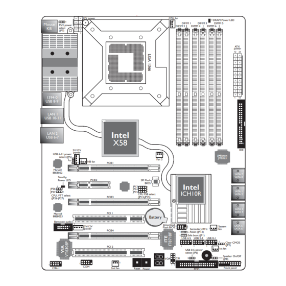
Hardware Installation Chapter 2 - Hardware Installation System Board Layout 12V power CPU fan DRAM Power LED DIMM 1 DIMM 3 DIMM 5 Mouse PS/2 power DIMM 2 DIMM 4 DIMM 6 select (J ) power 1394-0 USB 8-9 LAN 1 USB 10-11 LAN 2 Intel... -
Page 16: System Memory
Hardware Installation Warning: Electrostatic discharge (ESD) can damage your system board, proces- sor, disk drives, add-in boards, and other components. Perform the upgrade instruction procedures described at an ESD workstation only. If such a station is not available, you can provide some ESD protec- tion by wearing an antistatic wrist strap and attaching it to a metal part of the system chassis. -
Page 17: Hardware Installation
Hardware Installation Memory Configuration Single Channel Channel A Channel B Channel C DIMM2 DIMM1 DIMM4 DIMM3 DIMM6 DIMM5 1 module DS/SS 1 module DS/SS 1 module DS/SS “SS” denotes single-sided DIMM “DS” denotes double-sided DIMM “-” denotes no DIMM Note: DO NOT populate DIMM2, DIMM4 and DIMM6. -
Page 18: Installing The Memory Module
Hardware Installation Installing the Memory Module Note: The system board used in the following illustrations may not resemble the actual board. These illustrations are for reference only. 1. Make sure the PC and all other peripheral devices connected to it has been powered down. 2. -
Page 19: Bios Setting
Hardware Installation 6. Grasping the module by its edges, position the module above the socket with the “notch” in the module aligned with the “key” on the socket. The keying mechanism ensures the module can be plugged into the socket in only one way. 7. -
Page 20: Cpu
Hardware Installation Overview The system board is equipped with a surface mount LGA 1366 socket. This socket is exclusively designed for Intel Core i7 CPU. ® Important: 1. Before you proceed, make sure (1) the LGA 1366 1. Before you proceed, make sure (1) the LGA 1366 1. -
Page 21: Installing The Cpu
Hardware Installation Installing the CPU 1. Make sure the PC and all other peripheral devices connected to it has been powered down. 2. Disconnect all power cords and cables. 3. Locate the LGA 1366 CPU socket on the system board. Important: The CPU socket must not come in contact with... - Page 22 Hardware Installation 5. Lift the load lever. Load lever 6. Lift the load plate. Load plate 7. Remove the protective cap from the CPU socket. The cap is used to protect the CPU socket against dust and harmful par ticles. Re- move the protective cap only when you are about to install the CPU.
- Page 23 Hardware Installation 8. Insert the CPU into the socket. gold triangular mark on the CPU must align with the corner of the CPU socket shown on the right photo. Gold triangular mark Alignment key The CPU’s notch will at the same time fit into the socket alignment key.
-
Page 24: Installing The Fan And Heat Sink
Hardware Installation 9. Close the load plate. 10. Push the load lever down to lock the socket. The lever should hook onto the retention tab to indicate that the CPU is completely secured in the socket. Installing the Fan and Heat Sink The CPU must be kept cool by using a CPU fan with heat sink. - Page 25 Hardware Installation 2. Place the heat sink on top of the CPU. The 4 push-pins around the Mounting hole heat sink, which are used to secure the heat sink onto the system board, must match the 4 Intel ICH9R mounting holes around the socket.
- Page 26 Hardware Installation 5. Connect the CPU fan’s cable connector to the CPU fan connector on the system board.
-
Page 27: Flame-Freezer Heat Sink
Hardware Installation Flame-Freezer Heat Sink The system board uses the heatpipe technology. Heatpipe is an extremely high thermal conductor that can dissipate heat effectively. Aside from the heatpipe on the board, the provided Flame-Freezer heatsink provides additional cooling to the entire system. Due to space restrictions, the heat dissipating effect of a heatsink mounted directly at the place where the heat is produced (such as heat produced by the Nor thbridge) is sometimes limited. - Page 28 Hardware Installation Installing Flame-Freezer Inside the Chassis 1. The Nor thbridge's heatsink. is secured with two mounting screws. Northbridge heatsink Mounting screw Mounting screw 2. Remove mounting screws then remove the heatsink. Heatsink...
- Page 29 Hardware Installation 3. Now remove the metal rod prior to installing Flame-Freezer heatsink. Metal 4. Place Flame-Freezer on top of the heatsink base. Make sure it fits into groove previously occupied by the metal rod. Heatsink base 5. The Flame-Freezer can also be installed on the opposite side.
- Page 30 Hardware Installation 6. Replace the heatsink then use the mounting screws (removed in step secure heatsink and the Flame- Freezer in place. Installing Flame-Freezer at the External Rear Side of the Chassis 1. Before you proceed, make sure you have already installed the provided I/O shield and system board into the...
- Page 31 Hardware Installation 3. Remove mounting screws that hold the metal-plate- covering. Mounting screw Mounting screw 4. The heatsink base is now accessible. Prior to installing Flame-Freezer, you need to remove Heatsink base mounting clip...
- Page 32 Hardware Installation 5. The right photo shows the location of the mounting clip. Mounting screw Mounting clip Mounting screw Mounting screw Mounting clip 6. From the inside of the chassis, remove the two mounting screws that hold the mounting clip.
- Page 33 Hardware Installation 7. The right photo shows Flame-Freezer's heatsink base which is the part that must be inserted into the chassis. Heatsink base 8. From the external rear side of the chassis, inser t Flame- Freezer's heatsink base from a 45 angle.
- Page 34 Hardware Installation 10. Replace the metal clip and screws to stabilize Flame-Freezer. 11. Replace the metal-plate-covering previously removed in step 3. The right photo shows a properly installed Flame-Freezer.
-
Page 35: Jumper Settings
Hardware Installation Jumper Settings Clear CMOS Data Clearing CMOS Data using JP2 Intel ICH9R 1-2 On: Normal 2-3 On: (default) Clear CMOS Data If you encounter the following, a) CMOS data becomes corrupted. b) You forgot the supervisor or user password. c) The overclocked settings in the BIOS resulted to the system’s in- stability or caused system boot up problems. - Page 36 Hardware Installation ® Clearing CMOS Data using the EZ Clear Function ® EZ Clear bypasses the manual process of using a jumper to clear the CMOS by simply using the reset and power buttons. Important: ® EZ Clear is supported only if standby power is present in the system.
-
Page 37: Usb Power Select
Hardware Installation PS/2 Power Select 1-2 On: 5V 2-3 On: (default) 5VSB Important: The 5VSB power source of your power supply must suppor t ≥720mA. Intel ICH9R Selecting 5VSB will allow you to use the PS/2 keyboard or PS/2 mouse to wake up the system. USB Power Select USB 6-11 (JP5) - Page 38 Hardware Installation Speaker On/Off Select Intel ICH9R Buzzer 1-2 On: 2-3 On: Speaker Off Speaker On (default) The system board is equipped with a buzzer which serves as the PC’s speaker. By default the buzzer is “on” allowing you to hear the system’s beep messages and warnings.
- Page 39 Hardware Installation Safe Boot Intel ICH9R 1-2 On: 2-3 On: Default Safe boot This jumper is used to safely reboot the system whenever the sys- tem hangs and you are unable to restart the system. 1. Power-off the system then unplug the power cord. 2.
-
Page 40: Secondary Rtc Reset
Hardware Installation Secondary RTC Reset Intel ICH9R JP12 1-2 On: Normal 2-3 On: (default) RTC reset When the RTC batter y is removed, this jumper resets the manageability register bits in the RTC. Note: 1. The SRTCRST# input must always be high when all other RTC power planes are on. - Page 41 Hardware Installation CPU FSB Select JP13 Intel JP14 ICH9R JP15 By default, JP13 to JP15 are set to pins 1 and 2 On. This setting will allow the system to automatically run according to the CPU’s FSB. If you want to change the setting, please refer to the table below. By CPU FSB 1333 FSB 800...
- Page 42 Hardware Installation CPU_VTT Select JP26 1-2 On 2-3 On Intel ICH9R JP27 1-2 On 2-3 On JP26 and JP27 are used to select the CPU’s voltage. JP26 JP27 CPU_VTT 1-2 On 1-2 On 1.2V (default) 2-3 On 2-3 On 1.4V 2-3 On 1-2 On 1.6V...
-
Page 43: Rear Panel I/O Ports
Hardware Installation Rear Panel I/O Ports LAN 1 LAN 2 PS/2 Mouse 1394-0 PS/2 K/B USB 8-9 USB 10-11 USB 6-7 PS/2 Ports and IEEE 1394 Ports PS/2 Mouse PS/2 KB 1394-0 Intel ICH9R 1394-1 PS/2 Mouse and PS/2 Keyboard Ports These ports are used to connect a PS/2 mouse and a PS/2 key- board. - Page 44 Hardware Installation at the rear of the system chassis then connect the 1394 port cable to this connector. USB Ports and LAN Ports USB 9 USB 8 LAN 1 USB 11 USB 10 Intel ICH9R LAN 2 USB 7 USB 6 USB 4-5 USB 0-1 USB 2-3...
-
Page 45: Bernstein Audio Module
Hardware Installation Bernstein Audio Module Left audio channel Line-in Ground Ground Line-out Right audio channel Mic-in Center/ CD-in Subwoofer Rear R/L Side R/L 1 0 9 Line out Jet Detect Line out_Left S/PDIF-out Sense N. C. Line out_Right Mic Jet Detect S/PDIF-in Mic_Right Mic_Left... - Page 46 Hardware Installation Coaxial RCA S/PDIF-in and SPDIF-out Jacks These jacks are used to connect external audio output devices using coaxial S/PDIF cables. CD-in Connector The CD-in connector is used to receive audio from a CD-ROM drive, TV tuner or MPEG card. Front Audio Connector The front audio connector is used to connect to the line-out and mic-in jacks that are at the front panel of your system.
-
Page 47: Internal I/O Connectors
Hardware Installation 3. The length of the audio cable pro- vides the option and flexibility of in- stalling the module on any available expansion bracket slot at the rear of the system chassis. Remove the screw of the bracket where you want the audio module installed then remove the bracket. - Page 48 Hardware Installation Floppy Disk Drive Connector and IDE Connector Intel ICH9R Floppy Disk Drive Connector The floppy disk drive connector is used to connect a floppy drive. Insert one end of the floppy cable into this connector and the other end-most connector to the floppy drive.
- Page 49 Hardware Installation IrDA, CIR and Serial (COM) Connectors CIRTX IRTX Ground Ground Intel ICH9R CIRRX IRRX N. C. N. C. 5VSB IrDA CIR IrDA and CIR Connectors These connectors are used to connect an IrDA module and/or CIR module. Note: The sequence of the pin functions on some IrDA/CIR cable may be reversed from the pin function defined on the system board.
-
Page 50: Cooling Fan Connectors
Hardware Installation Cooling Fan Connectors Ground Power Sense Ground N. C. Speed Power Control Fan 3 CPU fan Power Ground N. C. Power Ground N. C. System fan Intel NB fan ICH9R Power Ground N. C. Ground N. C. Power 1st fan 2nd fan These fan connectors are used to connect cooling fans. - Page 51 Hardware Installation EZ Touch Switches Intel ICH9R Reset Power The presence of the power switch and reset switch on the system board are user-friendly especially to DIY users. They provide conven- ience in powering on and/or resetting the system while fine tuning the system board before it is installed into the system chassis.
- Page 52 Hardware Installation LEDs DRAM Power LED Standby Intel Power LED ICH9R Diagnostic DRAM Power LED This LED will light when the system’s power is on. Standby Power LED This LED will light when the system is in the standby mode. Diagnostic LED The Diagnostic LED displays POST codes.
-
Page 53: Power Connectors
Hardware Installation Power Connectors Use a power supply that complies with the ATX12V Power Supply Design Guide Version 1.1. An ATX12V power supply unit has a standard 24-pin ATX main power connector that must be inserted into this connector. 1 2 2 4 +3.3VDC +12VDC +5VDC... - Page 54 Hardware Installation The power connectors from the power supply unit are designed to fit the 24-pin and 8-pin connectors in only one orientation. Make sure to find the proper orientation before plugging the connectors. The FDD-type power connectors are additional power connector.s If you are using more than one graphics cards, we recommend that you plug power cables from your power supply unit to the 5V/12V power connectors.
- Page 55 Hardware Installation Restarting the PC Normally, you can power-off the PC by: 1. Pressing the power button at the front panel of the chassis. 2. Pressing the power switch that is on the system board (note: not all system boards come with this switch). If for some reasons you need to totally cut off the power supplied to the PC, switch off the power supply or unplug the power cord.
-
Page 56: Front Panel Connectors
Hardware Installation Front Panel Connectors Intel ICH9R RESET SPEAKER HD-LED PWR-LED ATX-SW HD-LED: Primary/Secondary IDE LED This LED will light when the hard drive is being accessed. RESET: Reset Switch This switch allows you to reboot without having to power off the system thus prolonging the life of the power supply or system. - Page 57 Hardware Installation Note: If a system did not boot-up and the Power/Standby LED did not light after it was powered-on, it may indicate that the CPU or memor y module was not installed properly. Please make sure they are properly inserted into their corresponding socket. Pin Assignment HD-LED HDD LED Power...
-
Page 58: Pci Express Slots
Hardware Installation PCI Express Slots PCIE 1 PCIE 2 Intel ICH9R PCIE 3 PCIE 4 PCI Express x16 Install PCI Express x16 graphics card, that comply to the PCI Ex- press specifications, into the PCI Express x16 slot. To install a graph- ics card into the x16 slot, align the graphics card above the slot then press it down firmly until it is completely seated in the slot. - Page 59 Hardware Installation Smart Connectors The Smart Connectors (USB, IEEE 1394 and Front Panel) serve as extended connectors allowing you to easily connect cables to the connectors that are on the system board. This is specially advantageous when using the front panel connectors as this will prevent wrong cable connection.
-
Page 60: Chapter 3 - Bios Setup
BIOS Setup Chapter 3 - BIOS Setup Award BIOS Setup Utility The Basic Input/Output System (BIOS) is a program that takes care of the basic level of communication between the processor and pe- ripherals. In addition, the BIOS also contains codes for various ad- vanced features found in this system board. -
Page 61: Standard Cmos Features
BIOS Setup Standard CMOS Features Use the arrow keys to highlight “Standard CMOS Features” then press <Enter>. A screen similar to the one below will appear. Phoenix - AwardBIOS CMOS Setup Utility Standard CMOS Features Date <mm:dd:yy> Tue, Jan 13 2009 Item Help Time <hh:mm:ss>... - Page 62 BIOS Setup IDE Channel 0 Master to IDE Channel 4 Slave To configure the IDE drives, move the cursor to a field then press <Enter>. The following screen will appear. Phoenix - AwardBIOS CMOS Setup Utility IDE Channel 0 Master Press Enter IDE HDD Auto-Detection Item Help...
- Page 63 BIOS Setup Capacity Displays the approximate capacity of the disk drive. Usually the size is slightly greater than the size of a formatted disk given by a disk checking program. Cylinder This field displays the number of cylinders. Head This field displays the number of read/write heads. Precomp This field displays the number of cylinders at which to change the write timing.
- Page 64 BIOS Setup Video This field selects the type of video adapter used for the primary system monitor. Although secondary monitors are supported, you do not have to select the type. The default setting is EGA/VGA. EGA/VGA Enhanced Graphics Adapter/Video Graphics Array. For EGA, VGA, SVGA and PGA monitor adapters.
- Page 65 BIOS Setup Extended Memory Displays the amount of extended memory detected during boot-up. Total Memory Displays the total memory available in the system.
-
Page 66: Bios Setup
BIOS Setup Advanced BIOS Features The Advanced BIOS Features allows you to configure your system for basic operation. Some entries are defaults required by the system board, while others, if enabled, will improve the performance of your system or let you set some features according to your preference. Phoenix - AwardBIOS CMOS Setup Utility Advanced BIOS Features Press Enter... -
Page 67: Removable Device Priority
BIOS Setup Removable Device Priority This field is used to select the boot sequence of the removable devices. Move the cursor to this field then press <Enter>. Use the Up or Down arrow keys to select a device then press <+> to move it up or <->... - Page 68 BIOS Setup Hard Disk Boot Priority This field is used to select the boot sequence of the hard drives. Move the cursor to this field then press <Enter>. Use the Up or Down arrow keys to select a device then press <+> to move it up or <->...
- Page 69 BIOS Setup Quick Power On Self Test This field speeds up Power On Self Test (POST) whenever the sys- tem is powered on. The BIOS will shorten or skip some check items during POST. To attain the shortest POST time, select “Fast”. First Boot Device, Second Boot Device, Third Boot Device and Boot Other Device Select the drive to boot first, second and third in the “First Boot...
- Page 70 BIOS Setup Gate A20 Option This field allows you to select how gate A20 is handled. Gate A20 is a device used to address memory above 1 Mbyte. Initially, gate A20 was handled via the keyboard controller. Today, while keyboards still provide this suppor t, it is more common, and much faster, for the system chipset to provide support for gate A20.
- Page 71 BIOS Setup Security Option This field determines when the system will prompt for the password- everytime the system boots or only when you enter the BIOS setup. Set the password in the Set Supervisor/User Password submenu. System The system will not boot and access to Setup will be denied unless the correct password is entered at the prompt.
-
Page 72: Advanced Chipset Features
BIOS Setup Advanced Chipset Features Phoenix - AwardBIOS CMOS Setup Utility Advanced Chipset Features System BIOS Cacheable Enabled Item Help Memory Hole at 15M-16M Disabled Menu Level Press Enter PCI Express Root Port Func Disabled IOH IOxAPIC Setting VT-d Disabled x VT-d Isoch Enabled Enabled... - Page 73 BIOS Setup Memory Hole At 15M-16M In order to improve system performance, certain space in memory can be reserved for ISA cards. This memory must be mapped into the memory space below 16MB. When enabled, the CPU assumes the 15-16MB memory range is allocated to the hidden ISA address range instead of the actual system DRAM.
- Page 74 BIOS Setup IOH IOxAPIC Setting The optioins are Enabled and Disabled. VT-d The optioins are Enabled and Disabled. VT-d Isoch The optioins are Enabled and Disabled. VT-d ATS The optioins are Enabled and Disabled. VT-d Interrupt Remapping The optioins are Enabled and Disabled.
-
Page 75: Integrated Peripherals
BIOS Setup Integrated Peripherals Phoenix - AwardBIOS CMOS Setup Utility Integrated Peripherals Item Help OnChip IDE Device Press Enter Onboard Device Press Enter Menu Level SuperIO Device Press Enter USB Device Setting Press Enter ↑↓→← : Move Enter: Select +/-/PU/PD: Value F10: Save ESC: Exit F1: General Help... - Page 76 BIOS Setup SATA Mode This field is used to configure the SATA devices supported by the southbridge. This option configures the Serial ATA drives as Parallel ATA storage devices. RAID This option allows you to create RAID or Intel Matrix Storage configuration on Serial ATA devices.
-
Page 77: Onboard Device
BIOS Setup Onboard Device Phoenix - AwardBIOS CMOS Setup Utility Onboard Device Item Help Onboard LAN Enabled Onboard LAN2 Enabled Menu Level Onboard 1394 Enabled Onboard HD Audio Enabled ↑↓→← : Move Enter: Select +/-/PU/PD: Value F10: Save ESC: Exit F1: General Help F5: Previous Values F6: Fail-Safe Defaults... -
Page 78: Super Io Device
BIOS Setup Super IO Device Phoenix - AwardBIOS CMOS Setup Utility SuperIO Device x Power On By Button Enabled Item Help Power On By Mouse Disabled Menu Level Disabled Power On By Keyboard Enter x KB Power On Password x Hot Key Power On Ctrl-F1 Onboard FDC Controller Enabled... - Page 79 BIOS Setup KB Power On Password Move the cursor to this field and press <Enter>. Enter your pass- word. You can enter up to 5 characters. Type in exactly the same password to confirm, then press <Enter>. The power button will not function once a keyboard password has been set in this field.
- Page 80 BIOS Setup UR2 Duplex Mode Half Data is completely transmitted before receiving data. Full Transmits and receives data simultaneously. PWRON After PWR-Fail When power returns after an AC power failure, the system’s power is off. You must press the Power button to power-on the system. When power returns after an AC power failure, the system will automatically power-on.
- Page 81 BIOS Setup USB Device Setting Phoenix - AwardBIOS CMOS Setup Utility USB Device Setting USB 1.0 Controller Enabled Item Help USB 2.0 Controller Enabled Menu Level USB Operation Mode High Speed USB Keyboard Function Enabled [Enable] or [Disable] USB Mouse Function Enabled Universal Host USB Storage Function...
- Page 82 BIOS Setup USB Mouse Function Due to the limited space of the BIOS ROM, the support for legacy USB mouse (in DOS mode) is by default set to Disabled. With more BIOS ROM space available, it will be able to support more advanced features as well as provide compatibility to a wide variety of peripheral devices.
-
Page 83: Power Management Setup
BIOS Setup Power Management Setup The Power Management Setup allows you to configure your system to most effectively save energy. Phoenix - AwardBIOS CMOS Setup Utility Power Management Setup ACPI Function Enable Item Help S3(STR) ACPI Suspend Type Menu Level Run VGABIOS if S3 Resume Auto Power Management... - Page 84 BIOS Setup ACPI Function By default, the ACPI function is enabled. This function should be enabled only in operating systems that support ACPI. ACPI Suspend Type This field is used to select the type of Suspend mode. S1(POS) Enables the Power On Suspend function. S3(STR) Enables the Suspend to RAM function.
- Page 85 BIOS Setup Video Off Method This determines the manner in which the monitor is blanked. V/H SYNC + Blank This selection will cause the system to turn off the vertical and horizontal synchronization ports and write blanks to the video buffer. Blank Screen This option only writes blanks to the video buffer.
- Page 86 BIOS Setup Soft-Off by PWR-BTTN This field allows you to select the method of powering off your system. Delay 4 Sec. Regardless of whether the Power Management func- tion is enabled or disabled, if the power button is pushed and released in less than 4 sec, the system enters the Suspend mode.
- Page 87 BIOS Setup Resume By Alarm Enabled When Enabled, you can set the time you would like the Soft Power Down (Soft-Off) PC to power-on in the “Time (dd:hh:mm) of Alarm” field. However, if the system is being accessed by incoming calls or the network prior to the time set in the field, the system will give priority to the incoming calls or network.
- Page 88 BIOS Setup PnP/PCI Configurations This section describes configuring the PCI bus system. It covers some very technical items and it is strongly recommended that only experienced users should make any changes to the default settings. Phoenix - AwardBIOS CMOS Setup Utility PnP/PCI Configurations Init Display First PCI Slot...
-
Page 89: Resources Controlled By
BIOS Setup Resources Controlled By The Award Plug and Play BIOS has the capability to automatically configure all of the boot and Plug and Play compatible devices. Auto(ESCD) The system will automatically detect the settings for you. Manual Choose the specific IRQ in the “IRQ Resources” field. -
Page 90: Pc Health Status
BIOS Setup PC Health Status Phoenix - AwardBIOS CMOS Setup Utility PC Health Status Shutdown Temperature Disabled Item Help CPUFan Fully ON If CPUTemp > 25 Menu Level CPUFan Turn OFF If CPUTemp < 25 SYSFan Fully ON If CHSTemp >... - Page 91 BIOS Setup CPUFan Turn Off If CPUTemp This field is used to select the CPU’s temperature at which the CPU fan will rotate at a start speed which is the slowest speed. Note: 1. If the CPU temperature runs between the highest (set in the “CPUFan Fully On If CPUTemp”...
- Page 92 BIOS Setup NB Fan Turn Off If NB Temp This field is used to select the Northbridge chip’s temperature at which the chip’s fan will rotate at a start speed which is the slowest speed. Note: If the Northbridge chip’s temperature runs between the highest (set in the “NB Fan Fully On If NB Temp”...
-
Page 93: Genie Bios Setting
BIOS Setup Genie BIOS Setting Aimed to provide convenience and superb overclockability, this submenu comes available in Easy mode (default mode) and Advance mode. Easy Mode Easy mode displays fields commonly used by users. Advance Mode If you intend to tweak your PC or boost its overclock features, you can switch the Genie BIOS Setting submenu from Easy mode to Advance mode by simply pressing <F9>... -
Page 94: Cpu Feature
BIOS Setup Phoenix - AwardBIOS CMOS Setup Utility Genie BIOS Setting Item Help CPU Feature Press Enter Press Enter DRAM Timing Menu Level Voltage Setting Press Enter Exit Setup Shut Down Mode 2 Enabled O.C Fail Retry Counter Disabled O.C Fail CMOS Reload PPM Function Enabled Enabled... - Page 95 BIOS Setup PPM Function The options are Enabled and Disabled. Turbo Mode Function The options are Enabled and Disabled. 1 Core Max Turbo Ratio to 4 Core Max Turbo Ratio These fields are used to enter the maximum turbo ratio. CPU Non-Turbo Clock Ratio This field is used to enter the CPU non-turbo clock ratio.
-
Page 96: Cpu Spread Spectrum
BIOS Setup CPU Spread Spectrum The options are Disabled, +-0.25% and +-0.30%. PCIE Spread Spectrum The options are Disabled, +-0.25% and +-0.30%. CPU Feature Move the cursor to this field and press <Enter>, the following screen will appear: Phoenix - AwardBIOS CMOS Setup Utility CPU Feature Set VR Current Limit Max Disabled... - Page 97 BIOS Setup CxE Function This field is used to select the C state supported by the CPU and system board. Execute Disable Bit When this field is set to Disabled, it will force the XD feature flag to always return to 0. Virtualization Technology When this field is set to Enabled, the VMM can utilize the additional hardware capabilities provided by Vanderpool Technology.
-
Page 98: Dram Timing
BIOS Setup DRAM Timing Move the cursor to this field and press <Enter>. The following screen will appear. Phoenix - AwardBIOS CMOS Setup Utility DRAM Timing Item Help Memory Control Setting Auto Memory LowGap 1536M Menu Level Auto DRAM Command Rate CAS Latency Time (tCL) Auto RAS# to CAS# Delay (tRCD) - Page 99 BIOS Setup RAS# to CAS# Delay (tRCD) This field is used to select the RAS# to CAS# delay time when reading and writing to the same bank. RAS# Precharge (tRP) This field is used to select the idle clocks after issuing a precharge command to the DRAM.
- Page 100 BIOS Setup Voltage Setting Move the cursor to this field and press <Enter>. The following screen will appear. Phoenix - AwardBIOS CMOS Setup Utility Voltage Setting Item Help O.C. Shut Down Free Enable O.C.S.D.F CPU VID Control Auto Menu Level CPU VID Special Add Limit Enabled CPU VID Special Add...
- Page 101 BIOS Setup CPU VID Control This field allows you to manually adjust to a higher core voltage that is supplied to the CPU. If you want to use the CPU’s default core voltage, leave this field in its default setting. The CPU’s Vcore will be generated according to the CPU VID configuration.
- Page 102 BIOS Setup VTT PWM Switch Frequency The options are Nominal Frequency, Reduce 15%, Reduce 30%, Increase 15% and Increase 30%. VTT PWM Phase Control The options are 2 Phase Operation and 1 Phase Operation. CPU PLL Voltage The options are 1.80V to 2.15V. IOH/ICH 1.1V Voltage The options are 1.11V to 1.73V.
- Page 103 BIOS Setup CPU QPI Drive Strength The options are Normal and Strong. IOH QPI Drive Strength The options are Normal and Strong. CPU Core Voltage This field will show the CPU’s current voltage. DRAM Voltage This field will show the DRAM’s current voltage. IOH Core Voltage This field will show the IOH core’s current voltage.
-
Page 104: Cmos Reloaded
BIOS Setup CMOS Reloaded The CMOS Reloaded submenu allows you to save different configu- rations and when needed, allows you to conveniently restore one of these previously saved configurations. Highlight CMOS Reloaded in the main menu then press <Enter>. Phoenix - AwardBIOS CMOS Setup Utility CMOS Reloaded Item Help Auto Save Bootable Setting... - Page 105 BIOS Setup Auto Save Bootable Setting This field is used to automatically save the last bootable setting from CMOS to an area in the SEEPROM referred to as the backup bank. To use this function: 1. Set this field to Enabled. 2.
- Page 106 BIOS Setup Saving, Loading and Naming BIOS Settings For overclockers who require different sets of settings for various system environments or operating systems, CMOS Reloaded allows you to save, load and name up to four sets of BIOS settings - in the “User Defined Setting Bank #1”...
- Page 107 BIOS Setup Load from this Bank To load the setting saved in the bank, move the cursor to “Load from this Bank” then press <Enter>. The setting in this bank will replace the current setting. Make sure to save before you exit the BIOS setup utility by selecting “Y”...
-
Page 108: Load Optimized Defaults
BIOS Setup Load Optimized Defaults The “Load Optimized Defaults” option loads optimized settings from the BIOS ROM. Use the default values as standard values for your system. Highlight this option in the main menu and press <Enter>. Phoenix - AwardBIOS CMOS Setup Utility Standard CMOS Features Genie BIOS Setting Advanced BIOS Features... -
Page 109: Set Supervisor Password
BIOS Setup Set Supervisor Password If you want to protect your system and setup from unauthorized entry, set a supervisor’s password with the “System” option selected in the Advanced BIOS Features. If you want to protect access to setup only, but not your system, set a supervisor’s password with the “Setup”... -
Page 110: Set User Password
BIOS Setup Set User Password If you want another user to have access only to your system but not to setup, set a user’s password with the “System” option se- lected in the Advanced BIOS Features. If you want a user to enter a password when trying to access setup, set a user’s password with the “Setup”... - Page 111 BIOS Setup Save & Exit Setup When all the changes have been made, highlight “Save & Exit Setup” and press <Enter>. Phoenix - AwardBIOS CMOS Setup Utility Standard CMOS Features Genie BIOS Setting Advanced BIOS Features CMOS Reloaded Advanced Chipset Features Load Optimized Defaults Integrated Peripherals Set Supervisor Password...
-
Page 112: Exit Without Saving
BIOS Setup Exit Without Saving When you do not want to save the changes you have made, high- light “Exit Without Saving” and press <Enter>. Phoenix - AwardBIOS CMOS Setup Utility Standard CMOS Features Genie BIOS Setting Advanced BIOS Features CMOS Reloaded Advanced Chipset Features Load Optimized Defaults... -
Page 113: Raid Bios
BIOS Setup RAID BIOS Intel RAID BIOS The Intel RAID BIOS utility is used to configure and manage RAID on Serial ATA drives connected to SATA 1 to SATA 6. When the system powers-up and all drives have been detected, the Intel RAID BIOS status message screen will appear. -
Page 114: Updating The Bios
Updating the BIOS To update the BIOS, you will need the new BIOS file and a flash utility, AWDFLASH.EXE. You can download them from DFI’s web site or contact technical support or your sales representative. 1. Save the new BIOS file along with the flash utility AWDFLASH.EXE to a floppy disk. - Page 115 BIOS Setup 6. The following will appear. Do You Want to Save BIOS (Y/N) This question refers to the current existing BIOS in your system. We recommend that you save the current BIOS and its flash utility; just in case you need to reinstall the BIOS. To save the current BIOS, press <Y>...
-
Page 116: Chapter 4 - Supported Software
Supported Software Chapter 4 - Supported Software Drivers, Utilities and Software Applications The DVD that came with the system board contains drivers, utilities and software applications required to enhance the performance of the system board. Insert the DVD into an optical drive. The screen shown below will appear. -
Page 117: Intel Chipset Device Software
Supported Software Intel Chipset Device Software On the top row of the screen, click the 1st icon to open the Chipset Driver menu. 1. Click “Intel(R) Chipset Device Software”. 2. The setup program is now ready to install the utility. Click Next. - Page 118 Supported Software 3. Read the license agree- ment then click Yes. 4. Go through the readme document for system requirements and instal- lation tips then click Next. 5. The setup program is now installing the driver. Click Next to continue.
- Page 119 Supported Software 6. Click “Yes, I want to restar t this computer now” then click Finish. Restar ting the system will allow the new software installation to take effect.
-
Page 120: Graphics Driver
Supported Software Graphics Driver On the top row of the screen, click the 2nd icon to open the Graphics Driver menu. The DVD provides both ATI and nVidia graphics drivers. Select the driver according to the graphics card that you are using. ATi Radeon Drivers 1. - Page 121 Supported Software 3. Select the language you like Catalyst Install Manager to display then click Next. 4. You are now ready to install the driver. Click Install.
- Page 122 Supported Software 5. Select the component (Express or Custom) you want to install then click Next. 6. Read license agreement then click Accept.
- Page 123 Supported Software 7. Click Yes to create the ATI Technologies folder. 8. Follow the remainder of the steps shown on the screen then restart the system to allow the new driver installation to take effect.
- Page 124 Supported Software nVidia GForce 8 Series Drivers 1. Click “nVidia GForce 8 Series Drivers”. 2. Read the license agree- ment then click “I accept the terms in the license agreement”. Click Next. 3. Click Next to install to the destination folder or click Change to select another folder.
- Page 125 Supported Software 4. The setup program will extract the files needed to install the driver on your computer. After all files have been extracted, click Next. 5. You are now ready to install the driver. Click Next. 6. Click “Yes, I want to restar t my computer now”...
-
Page 126: Realtek Audio Drivers
Supported Software Realtek Audio Drivers On the top row of the screen, click the 3rd icon to open the Audio Driver menu. 1. Click “Realtek Audio Drivers”. 2. The setup program is now ready to install the driver. Click Next. 3. - Page 127 Supported Software 4. Click “Yes, I want to restar t my computer now” then click Finish. Restarting the system will allow the new driver installation to take effect.
- Page 128 Supported Software Marvell LAN Drivers On the top row of the screen, click the 4th icon to open the Network Driver menu. 1. Click “Mar vell Drivers”. 2. The setup program is currently preparing the installation wizard to install the driver. 3.
- Page 129 Supported Software 4. Read license agreement then click “I accept the terms in the license agreement”. Click Next. 5. Click Install to begin the installation. 6. After completing installa- tion, click Finish to exit setup. Reboot your system for software installation to take effect.
- Page 130 Supported Software Creating a RAID Driver Floppy Diskette On the top row of the screen, click the 5th icon to open the RAID Driver menu. 1. Click “RAID Floppy Driver”. 2. Windows Explorer will appear showing the folder where the driver files are located in the DVD.
-
Page 131: Smart Guardian
Supported Software Smart Guardian The Smart Guardian utility is capable of monitoring the system’s tempera- ture, fan speed, voltage, etc. and allows you to manually set a range (High- est and Lowest Limit) to the items being monitored. If the settings/values are over or under the set range, a warning message will pop-up. - Page 132 Supported Software 3. Fill in the necessar y information then click Next.. 4. Click Next to install or click Browse to select another folder. 5. Select an option in accordance to the system that you are using then click Next.
- Page 133 Supported Software 6. After completing installa- tion, click Finish to exit setup. Restarting the system will allow the utility to take effect.
- Page 134 Supported Software Adobe Acrobat Reader 7.05 On the top row of the screen, click the last icon to open the Manuals menu. 1. Click “Adobe Acrobat Reader 7.05”. 2. Click Next to continue. 3. Setup is now ready to install. Click Next.
- Page 135 Supported Software 4. Click Next to install or click Change Destination Folder to select another folder. 5. Click Install to begin installation. 6. Click Finish to exit installaion.
-
Page 136: Installation Notes
Supported Software Installation Notes ® ® 1. "Autorun" ONLY supports the Windows XP and Windows Vista operating systems. If after inserting the CD, "Autorun" did not automatically start (which is, the Mainboard Utility CD screen did not appear), please go directly to the root directory of the CD and double-click "Setup". -
Page 137: Chapter 5 - Raid
RAID Chapter 5 - RAID The Intel ICH10R chip alows configuring RAID on Serial ATA drives connected to SATA 1 to SATA 6. It supports RAID 0, RAID 1, RAID 0+1 and RAID 5. The JMicron JMB363 chip allows configuring RAID on another 2 Se- rial ATA drives connected to SATA 7 and SATA 8. - Page 138 RAID Settings To enable the RAID function, the following settings are required. 1. Connect the Serial ATA drives. 2. Configure Serial ATA in the Award BIOS. 3. Configure RAID in the RAID BIOS. 4. Install the RAID driver during OS installation. 5.
- Page 139 RAID Configure RAID in the JMicron RAID BIOS When the system powers-up and all hard disk drives have been detected, the JMicron RAID BIOS status message screen will appear. Press the <Ctrl> and <J> keys simultaneously to enter the utility. The utility allows you to build a RAID system on Serial ATA drives.
- Page 140 RAID Step 5: Install the Intel Matrix Storage Manager The Intel Matrix Storage Manager can be installed from within Windows. It allows RAID volume management (create, delete, migrate) from within the operating system. It will also display useful SATA device and RAID volume information.
- Page 141 RAID 5. Read warning carefully then click Next. 6. Read license agreement then click Yes. 7. Go through the readme document view system requirements and installation information then click Next. 8. Follow the remainder of the steps shown on the screen; clicking “next” each time you finish a step.
- Page 142 RAID Step 6: Install the JMB36X Driver On the top row of the screen, click the 5th icon to open the RAID Driver menu. 1. Click “JMB36X Drivers”. 2. Setup is now ready to install the driver. Click Next. 3. Click Install to begin the installation.
- Page 143 RAID 4. Setup is now installing the driver. 5. Follow the remainder of the steps listed on the screen; clicking “next” each time you finish a step. 6. Click “Yes, I want to restar t my computer now” then click Finish. Restar ting the system will allow the new software installation to...
-
Page 144: Chapter 6 - Multiple Gpus
Multiple GPUs Chapter 6 - Multiple GPUs ATI CrossFireX Technology ATI’s CrossFireX technology drives your PC to a new peak of per- formance. By connecting two ATI CrossFireX graphics cards, the power of these multiple GPUs (Graphics Processing Units) within the system will accelerate your gaming performance and improve image quality. - Page 145 Multiple GPUs CrossFire Setup Note: • Uninstall all existing graphics card drivers before installing the ATI CrossFireX graphics cards. • Use identical ATI CrossFireX graphics cards. • The system board used in the following illustrations may not resemble the actual board. These illustrations are for refer- ence only.
- Page 146 Multiple GPUs 3. Align the ATI CrossFireX graphics cards above the PCIE 1 and PCIE 4 slots then press them down firmly until they are completely seated in the slot. Graphics card on PCIE4 Graphics card on PCIE1 4. Secure the graphics cards with the screws you removed in step 5.
- Page 147 Multiple GPUs 6. Insert the connectors that are at the ends of the cable to the connectors on top of the graphics cards. CrossFireX bridge 7. Connect auxiliary power source from the power supply unit to the graphics cards. 8. Connect a display device’s VGA or DVI cable to the graphics card.
- Page 148 Multiple GPUs Make sure you have installed the ATI Radeon drivers (ATI Catalyst Install Manager). Refer to chapter 4 of this manual for more information. 10. Install the graphics cards’ drivers. Refer to the user’s manual or documentation that came with the graphics cards for instructions on installing the drivers.
-
Page 149: Nvidia Sli Technology
Multiple GPUs NVIDIA SLI Technology ® The NVIDIA (Scalable Link Interface) technology connects identical SLI-ready graphics cards in a single and scalable system. Using the SLI bridge to connect the graphics cards will provide extreme performance allowing you to enjoy games with the most visual effects and the most graphics demanding multimedia utilities. - Page 150 Multiple GPUs 3-way SLI Remove the screw of the bracket that is opposite the PCIE 1, PCIE 3 and PCIE 4 slots then remove the brackets. PCIE 3 PCIE 4 PCIE 1 3. 2-way SLI Align the NVIDIA SLI graphics cards above the PCIE 1 and PCIE 4 slots then press them down firmly until they are completely seated in the slot.
- Page 151 Multiple GPUs 3-way SLI Align the NVIDIA SLI graphics cards above the PCIE 1, PCIE 3 and PCIE 4 slots then press them down firmly until they are completely seated in the slot. Graphics card Graphics card on PCIE4 on PCIE3 Graphics card on PCIE1 4.
- Page 152 Multiple GPUs 6. 2-way SLI Align the SLI bridge above the SLI connector of the graphics cards then insert the bridge until it is properly seated in place. SLI bridge 3-way SLI Align the SLI bridge above the SLI connector of the graphics cards then insert the bridge until it is properly seated in place.
- Page 153 Multiple GPUs Connect auxiliary power source from the power supply unit to the graphics cards. Connect a display device’s VGA or DVI cable to the graphics card. Make sure you have installed the nVidia GForce 8 Series Drivers. Refer to chapter 4 of this manual for more information. 10.
-
Page 154: Appendix A - Abs
ABS - Auto Boost System Appendix A - ABS: Auto Boost System The ABS (Auto Boost System) technology provides the convenience of saving and loading several OC settings. It allows you to use the best OC setting to optimize your system’s performance. - Page 155 ABS - Auto Boost System 3. The installation wizard is extracting files needed to install the utility. The wizard will lead you to complete the installation. 4. Setup is now ready to install the utility. Click Next. 5. Click Next to install to the destination folder or click Change to select another folder.
- Page 156 ABS - Auto Boost System 6. Click Install to begin the installation. 7. The installation wizard will copy all the necessary files and optimize the ABS features. 8. Click Finish to exit setup.
- Page 157 ABS - Auto Boost System The ABS Utility 1. To run the ABS utility, power up your system then press F1. The screen will show the CPU upgrade information. Press “Any Key” to continue. 2. When the system enters the operating system, the ABS utility will appear and display the system’s information.
- Page 158 ABS - Auto Boost System 5. Click Confirm. 6. ABS suppor ts Reloaded and Auto Upgrade features. Click Auto Upgrade. 7. Click Backup. 8. The default settings will appear on the screen. Click Save.
- Page 159 ABS - Auto Boost System 9. Enter a name for the default setting then click Save . You have just created a backup file of board’s default setting. 10. If in any case a new OC setting causes system instability, you can always retrieve the backup file saved earlier by clicking Reload.
- Page 160 ABS - Auto Boost System 12. Select the backup file then click Open. 13. Click Write to load Banks 1-4 into the BIOS. If you want the system to auto upgrade the setting the next time you boot the system, click “Enable Auto...
- Page 161 ABS - Auto Boost System 14. Click Yes to reboot. Important: 1. We strongly recommend that you backup the default setting. If in any case your overclock setting causes system instability, you can always retrieve the default setting by reloading the backup file. 2.
-
Page 162: Appendix B - Troubleshooting
Troubleshooting Appendix B - Troubleshooting Troubleshooting Checklist This chapter of the manual is designed to help you with problems that you may encounter with your personal computer. To efficiently troubleshoot your system, treat each problem individually. This is to ensure an accurate diagnosis of the problem in case a problem has multiple causes. -
Page 163: Power Supply
Troubleshooting The picture seems to be constantly moving. 1. The monitor has lost its vertical sync. Adjust the monitor’s vertical sync. 2. Move away any objects, such as another monitor or fan, that may be creating a magnetic field around the display. 3. -
Page 164: Hard Drive
Troubleshooting Hard Drive Hard disk failure. 1. Make sure the correct drive type for the hard disk drive has been entered in the BIOS. 2. If the system is configured with two hard drives, make sure the bootable (first) hard drive is configured as Master and the sec- ond hard drive is configured as Slave. - Page 165 Troubleshooting 3. Verify that the attached serial device works by attaching it to a serial port that is working and configured correctly. If the serial device does not work, either the cable or the serial device has a problem. If the serial device works, the problem may be due to the onboard I/O or the address setting.
-
Page 166: Appendix C -Debug Led Post And Troubleshooting
Debug LED POST and Troubleshooting Appendix C - Debug LED Post and Troubleshooting General Debug LED POST and Troubleshooting... - Page 167 Debug LED POST and Troubleshooting...
- Page 168 Debug LED POST and Troubleshooting...
- Page 169 Debug LED POST and Troubleshooting...
- Page 170 Debug LED POST and Troubleshooting Abnormal Debug LED POST and Troubleshooting...
Need help?
Do you have a question about the LanParty X58-T3eH8 and is the answer not in the manual?
Questions and answers