Table of Contents
Advertisement
Available languages
Available languages
Quick Links
Advertisement
Table of Contents

Subscribe to Our Youtube Channel
Related Manuals for TomTom LINK


Summary of Contents for TomTom LINK
- Page 1 Installation Guide...
-
Page 2: Table Of Contents
TomTom LINK installation guide Contents Sommaire inst allat guid Introduction Introduction Safety first La sécurité d'abord Technical data Données techniques Directives Directives Connection overview Schéma de connexion What’s in the box Contenu du coffret Inserting the SIM Card Insertion de la carte SIM Connecting to power Raccordement à... - Page 3 Collegamento dell'antenna GPS Ligar a antena GPS Collegamento dell'antenna GSM Ligar a antena GSM Test di funzionamento Testes de funcionamento Collegamento a TomTom WEBFLEET Ligar ao TomTom WEBFLEET Diagnostica Diagnósticos Collegamento di TomTom GO Ligar o TomTom GO Montaggio permanente...
-
Page 4: Introduction
TomTom LINK provides a large variety of functionalities. TomTom LINK is a GPS receiver and GSM/ GPRS module in one unit. With TomTom LINK you can easily obtain the current vehicle position including the mileage as read from the odometer. -
Page 5: Safety First
• Caution - danger through use in safety instructions. prohibited areas! The GSM module of the TomTom LINK is This document is part of the product. Keep it likely to cause interference to electric in safe custody and hand it to the new owner devices such as cardiac pacemakers, of the unit. - Page 6 Safety first WORK is authorised to perform repairs or replacement of parts • Warning - damage to the device! Short-circuits inside the unit can be caused by contact with water or other liquids. The unit may be damaged by contact with water.
-
Page 7: Technical Data
Technical data Techni cal data Dimensions Body: 145 x 75 x 36 mm Holder: 162 x 88 x 28 mm Weight Body: 200 g (without battery) Holder: 120 g Material Body: Injection moulded plastic body PC/ABS Holder: Santoprene Protection class IP 20 Supply voltage 12 V / 24 V / 36 V (min.9 V to max. -
Page 8: Directives
Directives Dire Declaration of conformity ctiv The unit described in this document is in accordance with the official European directives. A copy of the declaration of conformity can be provided. Type approval The telematics unit described in this document has received a type approval from the German Federal Bureau of Motor Vehicles and Drivers. -
Page 9: Connection Overview
Connection overview Connec tion overvie... - Page 10 Connection overview...
-
Page 11: What's In The Box
External GSM antenna with cleaning cloth Power cable Terminal cable Fixatives - 3 self-tapping screws and washers, 2 sticky pads 2 fast-blow 2A motor vehicle fuses with holders Self-adhesive disc (to fix the TomTom GO windscreen dock on the dashboard) -
Page 12: Inserting The Sim Card
Inserting the SIM Card Inse For the transmission process rting To prepare the TomTom LINK for data exchange with TomTom WEBFLEET you need to insert the SIM Card in the unit. 1. Press the release button for the SIM Card holder with a pointed object until it releases. -
Page 13: Connecting To Power
Connecting to power Connec Important! Connect TomTom LINK to vehicle ting to power voltage (12 V / 24 V / 36 V). Do not connect to a voltage converter. The three wires GND, IGN and PWR+ (supply voltage) must be connected. -
Page 14: Connecting Gps Antenna
GPS antenna (supplied with an integrated surface or use the extra sticky pad. magnet and an extra sticky pad) must be connected to the TomTom LINK. Important note • Tinted metallised windscreens or those with integrated filament heating may obstruct GPS reception. -
Page 15: Connecting Gsm Antenna
The GSM antenna with sticky pad must be 4. Press the GSM antenna, in the vertical ting antenn connected to TomTom LINK to provide position, against the inside of your communication with TomTom WEBFLEET. windscreen until it sticks. Important note Note: The sticky, bottom side of the antenna has to face the outside of the vehicle. -
Page 16: Testing Operation
GPS and GSM chapters. reception. For details see the table under ’Diagnostics’. 1. Please check all connections to TomTom LINK (wires, fuses and antennas). 1. Turn on the ignition. 2. Check that the SIM Card is inserted 2. -
Page 17: Linking To Tomtom Webfleet
TomTom WEBFLEET account with a valid first position report. Before starting the linking process, the TomTom LINK serial number and the SIM ID must have been registered. Visit www.tomtomwork.com/activate and follow the instructions to register. To start the linking process: 1. -
Page 18: Diagnostics
Diagnostics Diag Monitoring operation nost Monitor the operation of the TomTom LINK according to the table below. Flashing (permanently) Successfully linked to In linking mode Not linked to TomTom (SYS) TomTom WEBFLEET WEBFLEET Yellow GSM registered, but Not registered, trying to... -
Page 19: Connecting Tomtom Go
Connecting TomTom GO Connec If you want to use the TomTom GO (510/710/ ting TomTo m GO 910) together with TomTom LINK for receiving orders, text messages and navigation orders, and for communicating with the office, you need to connect the TomTom GO to TomTom LINK. -
Page 20: Permanent Mounting
TomTom LINK. 2. Insert the three screws into the corresponding holes in the holder. 3. Tighten the screws. 4. Insert the TomTom LINK in the holder until it fully engages. Important Make sure you do not damage the TomTom LINK. - Page 21 Permanent mounting Using sticky pads You can also affix the TomTom LINK with the two sticky pads. Follow the safety instructions in this document. 1. Choose a flat surface for accurate positioning of the TomTom LINK. 2. Clean the surface with a clean and dry cloth, so that the surface is oil free, dry and clean.
-
Page 22: Input And Output
The connected load must be ground. With the inputs of TomTom LINK, up connected between GND and OUT 1. Loads to five inputs (on/off) can be recorded. It is requiring more than 0.5 A must be controlled possible, for instance, to monitor digital with relays. -
Page 23: Einführung
TomTom LINK bietet Ihnen eine eindrucksvolle Funktionsvielfalt. TomTom LINK vereint einen GPS-Empfänger und ein GSM/GPRS-Modul in einem einzigen Gerät. Mit TomTom LINK können Sie sich problemlos über die aktuelle Position Ihres Fahrzeuges einschließlich der vom Tacho übermittelten Kilometerleistung informieren. Alle Daten werden per GPRS übertragen. Die Daten können bei einer vorübergehenden... -
Page 24: Sicherheit Geht Vor
• Achtung – Gefahr beim Betrieb in • Wichtig – Eine unsachgemäße Installation unzulässiger Umgebung! kann Schäden verursachen! Das GSM-Modul des TomTom LINK kann Die Installation und Inbetriebnahme des bei elektrischen Geräten – z. B. Geräts darf ausschließlich durch Herzschrittmachern, Hörgeräten, autorisiertes Personal erfolgen, medizinischen Geräten für die... - Page 25 Sicherheit geht vor! Verletzungs- und Lebensgefahr. Verwenden Sie das Gerät daher nicht in hoch explosionsgefährdeten Bereichen! Wenn Sie Ihren TomTom LINK in einem flüssiggasbetriebenen Fahrzeug verwenden, beachten Sie die Sicherheitsvorschriften des Landes, in dem das Fahrzeug betrieben wird. • Warnung – Reparatur und Austausch! Reparaturen dürfen nur von autorisiertem...
-
Page 26: Technische Daten
Technische Daten hnis Date Abmessungen Gehäuse: 145 x 75 x 36 mm Halterung: 162 x 88 x 28 mm Gewicht Gehäuse: 200 g (ohne Batterie) Halterung: 120 g Material Gehäuse: Kunststoffspritzguss PC/ABS Halterung: Santoprene Schutzklasse IP 20 Versorgungsspannung 12 V / 24 V / 36 V (min. 9 V – max. 48 V) Stromverbrauch Bei 14 V: <... -
Page 27: Richtlinien
Richtlinien Richtlin Konformitätserklärung Das in diesem Dokument beschriebene Gerät entspricht den geltenden europäischen Richtlinien. Eine Kopie der Konformitätserklärung kann zur Verfügung gestellt werden. Bauartzulassung Das in diesem Dokument beschriebene Telematikgerät besitzt eine vom Deutschen Kraftfahrtbundesamt vergebene Bauartzulassung. -
Page 28: Anschlussübersicht
Anschlussübersicht Ansc hluss über sicht... - Page 29 Anschlussübersicht...
-
Page 30: Lieferumfang
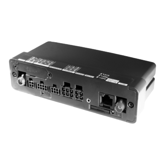
Lieferumfang Lief TomTom LINK Black Box GPS-Antennenanschluss (FAKRA blau) CAN-Bus-Anschluss Rückstellknopf (RESET) Anschluss für Terminal-Kabel Spannungsversorgungsanschluss SIM-Kartenhalter Auswurfknopf für SIM-Kartenhalter GSM-Antennenanschluss (FAKRA dunkelrot) IO-Anschluss 3 LEDs (SYS, GSM, GPS) Service/Update-Anschluss Halterung Externe GPS-Antenne, selbstklebend, mit Reinigungstuch Externe GSM-Antenne mit Reinigungstuch... -
Page 31: Sim-Karte Einsetzen
SIM-Karte einsetzen SIM- SIM-Karte für die Übertragung einsetzen Karte einsetz Um den TomTom LINK für den Datenaustausch mit TomTom WEBFLEET vorzubereiten, müssen Sie die SIM-Karte in das Gerät einsetzen. 1. Drücken Sie mit einem spitzen Gegenstand auf den Auswurfknopf des SIM- Kartenhalters, bis die Arretierung des Kartenhalters gelöst wird. -
Page 32: Anschluss An Die Stromversorgung
Anschluss an die Stromversorgung Wichtig! Schließen Sie den TomTom LINK an chlu die Bordstromversorgung (12 V/24 V/36 V) an. Stro rsor Verwenden Sie keinen Spannungswandler. Die drei Leitungen GND (Masse), IGN (Zündung) und PWR+ (Versorgungsspannung) müssen alle angeschlossen werden. 1. Schließen Sie das IGN-Kabel (Zündung) und das PWR+ Kabel (Versorgungs- spannung) über getrennte, 2 A/flink... -
Page 33: Gps-Antenne Anschließen
Antenne anschlie ßen GPS-Antenne (ausgestattet mit Klebestreifen Oberseite zum Himmel gerichtet auf einer und integriertem Magnet) an den TomTom glatten Oberfläche am Armaturenbrett in Link an. der Nähe der Windschutzscheibe. Benutzen Sie dazu entweder eine glatte Metalloberfläche oder den zusätzlichen Wichtiger Hinweis Klebestreifen. -
Page 34: Gsm-Antenne Anschließen
2. Bereiten Sie eine saubere, fettfreie und e ansc den TomTom LINK angeschlossen werden, trockene Befestigungsfläche auf der hlie ßen um die Verbindung zu TomTom WEBFLEET zu Innenseite der Windschutzscheibe vor. ermöglichen. 3. Entfernen Sie die Schutzfolie von der Haftfläche der GSM-Antenne. Wichtiger Hinweis •... -
Page 35: Funktionsprüfung
Schritte ordnungsgemäß ausgeführt haben. Details entnehmen Sie der Tabelle unter ’Funktionsanalyse’. 1. Bitte überprüfen Sie alle Verbindungen zum TomTom LINK (Kabel, Sicherungen 1. Schalten Sie die Zündung ein. und Antennen). 2. Beobachten Sie die gelbe GSM-LED und 2. Überprüfen Sie, dass die SIM-Karte korrekt die grüne GPS-LED. -
Page 36: Verbinden Mit Tomtom Webfleet
Antennenüberprüfung können Sie eine Verbindungsaufbau ein Fehler aufgetreten. Verbindung zu TomTom WEBFLEET Überprüfen Sie, ob die TomTom-LINK- herstellen. Nach dem Herstellen der Seriennummer und die SIM-ID bei Verbindung erscheint das Fahrzeug mit einem TomTom WEBFLEET registriert wurden ersten gültigen Positionsbericht im TomTom-... -
Page 37: Funktionsanalyse
Funktionsanalyse Funktio Betriebsüberwachung nsanaly Der Betrieb des TomTom LINK kann anhand der nachfolgenden Tabelle überwacht werden. Blinkt (dauerhaft) Leuchtet Verbindung zu Verbindungsversuch im Nicht mit TomTom (SYS) TomTom WEBFLEET Gange WEBFLEET verbunden hergestellt Gelb Im GSM-Netz Nicht angemeldet, GPRS-Verbindung (GSM) -
Page 38: Verbindung Mit Tomtom Go Herstellen
Verbindung mit TomTom GO herstellen Sie können einen TomTom GO (510/710/910) bind mit Ihrem TomTom LINK verbinden, um hers telle Aufträge, Textnachrichten und Navigationsanweisungen zu empfangen und mit Ihrer Zentrale zu kommunizieren. 1. Schließen Sie den Stecker des Terminal- Kabels an den Anschluss für das Terminal- Kabel an. -
Page 39: Festeinbau
2. Führen Sie die drei Schrauben in die Bohrungen der Halterung ein. 3. Ziehen Sie die Schrauben fest. 4. Legen Sie Ihren TomTom LINK so in die Halterung ein, dass er einrastet. Wichtig Achten Sie darauf, Ihren TomTom LINK nicht zu beschädigen. - Page 40 Festeinbau Mit Klebestreifen Sie können Ihren TomTom LINK auch mit den zwei Klebestreifen befestigen. Bitte beachten Sie die Sicherheitshinweise in diesem Dokument. 1. Wählen Sie eine ebene Oberfläche, auf der Ihr TomTom LINK korrekt aufgestellt werden kann. 2. Reinigen Sie die Oberfläche mit einem sauberen, trockenen Tuch und stellen Sie sicher, dass die Oberfläche fettfrei, trocken...
-
Page 41: Eingänge Und Ausgänge
(im aktiven Zustand stromführend). Der gelegt werden. Die Eingänge von TomTom angeschlossene Verbraucher muss zwischen LINK können bis zu fünf Eingangssignale (Ein/ der Masse (GND) und dem Ausgang 1 (OUT 1) Aus) erfassen. So lassen sich digitale angeschlossen werden. Bei einem Ereignisse, wie z. -
Page 43: Introduction
Vous avez choisi l'un des appareils de télématique les plus réputés et fiables du marché. Le TomTom LINK vous offre un large éventail de fonctionnalités. Il intègre dans une seule et même unité un récepteur GPS et un module GSM/GPRS. Avec le TomTom LINK, vous obtenez facilement la position courante du véhicule, y compris le... -
Page 44: La Sécurité D'abord
Ceci risque de châssis! mettre en danger la santé et la vie des Assurez-vous de ne pas percer dans des personnes. Veuillez ne pas utiliser le endroits du châssis ayant des fonctions TomTom LINK dans les zones où il y a un... - Page 45 La sécurité d'abord grand risque d'explosion! Si vous utilisez le TomTom LINK dans un véhicule alimenté au gaz liquéfié (GPL), veuillez suivre les règlements de sécurité du pays où le véhicule est utilisé. • Attention: réparation et remplacement! Les réparations peuvent uniquement être effectuées par du personnel agréé...
-
Page 46: Données Techniques
Données techniques née tech niqu Dimensions Appareil : 145 x 75 x 36 mm Support : 162 x 88 x 28 mm Poids Appareil : 200 g (sans batterie) Support : 120 g Matières Appareil : Corps en plastique PC/ABS moulé par injection Support : santoprène Classe de protection IP 20... -
Page 47: Directives
Directives Directiv Déclaration de conformité Le produit décrit dans ce document est conforme aux directives européennes officielles. Une copie de la déclaration de conformité peut vous être délivrée. Homologation de type Le produit de télématique décrit dans ce document a reçu une homologation de type de l'Office Fédéral allemand pour la circulation routière. -
Page 48: Schéma De Connexion
Schéma de connexion Sché conn exio... - Page 49 Schéma de connexion...
-
Page 50: Contenu Du Coffret
Câble du terminal Éléments de fixation: 3 vis autotaraudeuses et rondelles, 2 adhésifs de fixation 2 fusibles à fusion rapide, 2 A (ampères), avec porte-fusibles Disque auto-adhésif (pour attacher le Socle pour pare-brise du TomTom GO au tableau de bord) -
Page 51: Insertion De La Carte Sim
Insertio Pour le processus de transmission n de la carte Afin de préparer le TomTom LINK à l'échange de données avec TomTom WEBFLEET, vous devez insérer la carte SIM dans l'appareil. 1. Appuyez sur le bouton d'ouverture du support de carte SIM avec un objet pointu. -
Page 52: Raccordement À L'alimentation
Raccordement à l'alimentation Important! Raccordez votre TomTom LINK à cord nt à l'ali une tension automobile (12 V / 24 V / 36 V). Ne tatio le branchez pas sur un transformateur. Les trois fils - terre, contact et phase PWR+ doivent être branchés. -
Page 53: Connexion De L'antenne Gps
Choisissez une surface métallique lisse ou un aimant intégré et un adhésif de fixation utilisez l'adhésif de fixation supplémentaire. supplémentaire) doit être connectée au TomTom LINK. Important! • Les pare-brises athermiques teintés ou les pare-brises chauffants peuvent entraver la réception GPS. Installez l'antenne GPS derrière la vitre arrière ou... -
Page 54: Connexion De L'antenne Gsm
L'antenne GSM avec son support adhésif doit 4. Appuyez l'antenne GSM en position nexi l'ant être connectée au TomTom LINK pour assurer verticale contre l'intérieur de votre pare- la communication avec TomTom WEBFLEET. brise jusqu'à ce qu'elle adhère à celui-ci. -
Page 55: Tests
’Diagnostic’. 1. Veuillez vérifier toutes les connexions au 1. Mettez le contact. TomTom LINK (câbles, fusibles et 2. Surveillez le témoin lumineux GSM jaune et antennes). le témoin lumineux GPS vert. Tous deux 2. Assurez-vous que la carte SIM est commencent à... -
Page 56: Liaison Avec Tomtom Webfleet
TomTom Assurez-vous d'avoir enregistré le numéro WEBFLEET. Une fois la liaison établie, le de série TomTom LINK et l'identité de la véhicule sera disponible dans le compte carte SIM auprès de TomTom WEBFLEET TomTom WEBFLEET du client avec un et d'avoir effectué... -
Page 57: Diagnostic
Diagnostic Diagno Contrôle du fonctionnement stic Contrôlez le fonctionnement du TomTom LINK comme indiqué dans le schéma ci- dessous. Eteint Clignotant (permanent) Allumé Rouge Relié correctement à En mode liaison Non relié correctement à (SYS) TomTom WEBFLEET TomTom WEBFLEET Jaune GSM enregistré, mais... -
Page 58: Connexion Du Tomtom Go
Connexion du TomTom GO Si vous souhaitez utiliser le TomTom GO (510/ nexi 710/910) avec le TomTom LINK pour recevoir des commandes, des messages texte et des ordres de navigation ou pour communiquer avec votre bureau, vous devez le connecter au TomTom LINK. -
Page 59: Fixation Permanente
TomTom LINK. 2. Insérez les trois vis dans les trous correspondants du support. 3. Serrez les vis. 4. Insérez le TomTom LINK dans le support jusqu'à ce qu'il soit entièrement engagé. Important Attention de ne pas endommager votre TomTom LINK. - Page 60 LINK. Réitérez l'opération avec le second adhésif de fixation. 4. Ôtez les films protecteurs de l'autre face des deux adhésifs. 5. Placez le TomTom LINK avec ses adhésifs de fixation sur la surface préparée. Appuyez délicatement et maintenez-le ainsi pendant quelques secondes jusqu'à ce qu'il adhère.
-
Page 61: Entrée Et Sortie
Pour utiliser les entrées, celles-ci doivent être et sortie elle est active. La charge connectée doit l'être reliées à la terre. Le TomTom LINK peut entre la terre et OUT 1. Les charges requérant enregistrer jusqu'à cinq entrées (marche/ plus de 0,5 A doivent être contrôlées par des arrêt). -
Page 63: Inleiding
Het apparaat bevat zowel een GPS-ontvanger als een GSM/GPRS-module. Met TomTom LINK kunt u gemakkelijk de positie van een voertuig bepalen en de afgelegde afstand aflezen van de kilometerteller. Alle gegevens worden verzonden via GPRS. -
Page 64: Veiligheid
• Let op - gevaar door gebruik in gebieden waar dit niet is toegestaan! • Belangrijk - schade veroorzaakt door De GSM-module van de TomTom LINK kan onjuiste installatie! interferentie veroorzaken bij elektrische De installatie en eerste bediening van het... - Page 65 Veiligheid gevaar komen. Gebruik het apparaat niet op plaatsen met een hoog explosiegevaar! Wanneer u de TomTom LINK gebruikt in een voertuig dat op gas rijdt, moet u de veiligheidsvoorschriften volgen van het land waarin het voertuig wordt gebruikt. • Waarschuwing - reparatie en vervanging!
-
Page 66: Technische Gegevens
Technische gegevens Tech nisch gege vens Afmetingen Apparaat: 145 x 75 x 36 mm Houder: 162 x 88 x 28 mm Gewicht Apparaat: 200 g (zonder batterij) Houder: 120 g Materiaal Apparaat: Spuitgegoten kunststof behuizing PC/ABS Houder: Santopreen Veiligheidsklasse IP 20 Voedingsspanning 12 V / 24 V / 36 V (min. -
Page 67: Richtlijnen
Richtlijnen Richtlij Conformiteitsverklaring Het in deze handleiding beschreven apparaat voldoet aan de officiële Europese richtlijnen. Een kopie van de conformiteitsverklaring kan worden opgevraagd. Typegoedkeuring Aan het telematica-apparaat dat wordt beschreven in deze handleiding is een typegoedkeuring verleend door het Duitse KBA (Kraftfahrt-Bundesamt). -
Page 68: Aansluitschema
Aansluitschema Aans luits... - Page 69 Aansluitschema...
-
Page 70: Wat Zit Er In De Doos
Externe GSM-antenne met schoonmaakdoekje Voedingskabel Terminalkabel Bevestigingsmateriaal - 3 zelftappende schroeven en tussenringen, 2 dubbelzijdige stickers 2 snelle glaszekeringen (2 A, fast-blow) met houders voor motorvoertuigen Zelfklevende schijf (voor bevestiging van de TomTom GO voorruitdock op het dashboard) -
Page 71: De Sim-Kaart Plaatsen
Voor de gegevensoverdracht SIM- kaart plaatse Om gegevensoverdracht mogelijk te maken tussen de TomTom LINK en TomTom WEBFLEET moet u de SIM-kaart in het apparaat plaatsen. 1. Druk met een puntig voorwerp op de vrijgaveknop van de SIM-kaarthouder, zodat deze vrij komt. -
Page 72: Aansluiten Van Voedingsspanning
Aansluiten van voedingsspanning Belangrijk! Sluit de TomTom LINK aan op de sluit accuspanning van het voertuig (12 V / 24 V / 36 ding sspa nnin V). Gebruik geen transformator. De drie draden GND (aarde), IGN (ontsteking) en PWR+ (voedingsspanning) moeten zijn aangesloten. -
Page 73: De Gps-Antenne Aansluiten
Kies hiervoor een glad metalen de TomTom LINK. oppervlak uit of gebruik de extra sticker. Belangrijke opmerking • Getinte, zonwerende voorruiten of voorruiten met geïntegreerde... -
Page 74: De Gsm-Antenne Aansluiten
4. Druk de GSM-antenne in verticale positie ante moet worden aangesloten op de TomTom tegen de binnenkant van de voorruit, tot sluit LINK om te kunnen communiceren met deze blijft zitten. TomTom WEBFLEET. Opmerking: De onderkant van de antenne, met plaklaag, moet naar buiten gericht zijn. -
Page 75: Testen Van Het Apparaat
GPS- en GSM-signaal mogelijk te maken. Voor meer gedetailleerde informatie zie de tabel in 1. Controleer of alle onderdelen zijn het hoofdstuk ’Diagnostiek’. aangesloten op de TomTom LINK (bedrading, zekeringen en antennes). 1. Start de motor. 2. Controleer of de SIM-kaart op de juiste 2. -
Page 76: Verbinden Met Tomtom Webfleet
Voordat u begint met het verbindingsproces moet u het TomTom LINK serienummer en de SIM-ID registreren. Ga naar www.tomtomwork.com/activate en volg de instructies om ze te registreren. Om verbinding te maken doet u het volgende: 1. -
Page 77: Diagnostiek
Diagnostiek Diagno Controleren of alles werkt stiek Controleer of de TomTom LINK goed werkt aan de hand van de onderstaande tabel. Knipperend (constant) Rood Verbonden met In verbindingsmodus Niet verbonden met (SYS) TomTom WEBFLEET TomTom WEBFLEET Geel GSM geregistreerd, Niet geregistreerd, bezig... -
Page 78: De Tomtom Go Aansluiten
De TomTom GO aansluiten Als u de TomTom GO (510/710/910) samen met de TomTom LINK wilt gebruiken voor het sluit ontvangen van instructies, tekstberichten, navigatieaanwijzingen en als u wilt communiceren met kantoor, dient u de TomTom GO aan te sluiten op de TomTom LINK. -
Page 79: Permanente Montage
TomTom LINK. 2. Plaats de drie schroeven in de bijbehorende gaten in de houder. 3. Draai de schroeven aan. 4. Plaats de TomTom LINK in de houder tot deze stevig vastzit. Belangrijk Let op dat u de TomTom LINK niet beschadigt. - Page 80 5. Plaats de TomTom LINK met de stickers naar beneden op het geprepareerde oppervlak. Druk hem voorzichtig aan en houd hem een paar seconden vast totdat hij vast blijft zitten. Belangrijk Let op dat u de TomTom LINK niet beschadigt. Volg de veiligheidsvoorschriften in deze handleiding.
-
Page 81: Ingang En Uitgang
De stroomverbinding zorgen dat deze geaard is. Met de ingangen op moet gelegd worden tussen GND (aarde) en de TomTom LINK kunnen maximaal vijf OUT 1. Elektrische spanning die meer dan 0,5 ingangen (aan/uit) worden geregistreerd. Het A vereist, moet worden geregeld via een is bijvoorbeeld mogelijk om digitale relais. -
Page 83: Introduzione
Potrete ricevere ordini con le coordinate di destinazione su TomTom LINK e con la semplice pressione di un pulsante sarà attivata la navigazione che guiderà l'autista fino alla destinazione. -
Page 84: Regole Principali Per La Sicurezza
Quando si utilizza TomTom comandi. LINK in un veicolo alimentato a gas liquido, seguire le norme per la sicurezza del paese • Attenzione - danni al telaio! in cui si utilizza il veicolo. - Page 85 Non sostituire assolutamente le parti danneggiate dell'unità da soli. Consegnare l'unità difettosa a TomTom WORK. Solo lo staff qualificato di TomTom WORK è autorizzato a eseguire le riparazioni o la sostituzione delle parti. • Avvertenza - danni al dispositivo! I cortocircuiti all'interno dell'unità...
-
Page 86: Dati Tecnici
Dati tecnici Dati tecn Dimensioni Corpo: 145 x 75 x 36 mm Supporto: 162 x 88 x 28 mm Peso Corpo: 200 g (senza batteria) Supporto: 120 g Materiale Corpo: corpo in plastica stampata ad iniezione PC/ABS Supporto: Santoprene Classe di protezione IP 20 Tensione di alimentazione 12 V / 24 V / 36 V (da min. -
Page 87: Direttive
Direttive Direttiv Dichiarazione di conformità L'unità descritta nel presente documento soddisfa le direttive ufficiali europee. Può essere fornita una copia della dichiarazione di conformità. Omologazione L'unità telematica descritta nel presente documento ha ricevuto un'omologazione dall'ufficio della motorizzazione civile. -
Page 88: Panoramica Del Collegamento
Panoramica del collegamento coll... - Page 89 Panoramica del collegamento...
-
Page 90: Contenuto Della Confezione
Contenuto della confezione Scatola nera di TomTom LINK tenu dell a conf Connettore antenna GPS (FAKRA blu) ezio Connettore cavo CAN bus Pulsante di reimpostazione Connettore cavo terminale Connettore cavo di alimentazione Supporto carta SIM Pulsante di rilascio per supporto carta... -
Page 91: Inserimento Della Carta Sim
Per il processo di trasmissione ento della carta Per preparare TomTom LINK per lo scambio dei dati con TomTom WEBFLEET, occorre inserire la carta SIM nell'unità. 1. Premere il pulsante di rilascio del supporto della carta SIM con un oggetto appuntito finché... -
Page 92: Collegamento All'alimentazione
Collegamento all'alimentazione Coll Importante! Collegare TomTom LINK alla all'al tensione del veicolo (12 V / 24 V / 36 V). Non ntazi collegare a un convertitore di tensione. Devono essere collegati i tre fili GND, IGN e PWR+ (tensione di alimentazione). -
Page 93: Collegamento Dell'antenna Gps
GPS (fornita con un magnete oppure utilizzare il cuscinetto extra integrato e un cuscinetto extra adesivo) deve adesivo. essere collegata a TomTom LINK. Importante • I parabrezza metallizzati o quelli con filamenti integrati che si riscaldano possono ostruire la ricezione GPS. -
Page 94: Collegamento Dell'antenna Gsm
Collegamento dell'antenna GSM Coll L'antenna GSM dotata di cuscinetto adesivo 4. Premere l'antenna GSM, in posizione dell' deve essere collegata a TomTom LINK per verticale, contro la parte interna del ante abilitarne la comunicazione con TomTom parabrezza finché non aderisce WEBFLEET. -
Page 95: Test Di Funzionamento
GPS e GSM. Per ulteriori dettagli vedere la tabella riportata nel 1. Controllare tutti i collegamenti a TomTom capitolo "Diagnostica". LINK (fili, fusibili e antenne). 1. Accendere il veicolo. -
Page 96: Collegamento A Tomtom Webfleet
Prima di avviare il processo di collegamento, occorre registrare il numero seriale di TomTom LINK e l'ID della SIM. Visitare il sito www.tomtomwork.com/activate e seguire le istruzioni per la registrazione. Per avviare il processo di collegamento: 1. -
Page 97: Diagnostica
Diagnostica Diagno Monitoraggio del funzionamento stica Monitorare il funzionamento di TomTom LINK in base alla tabella sottostante. Lampeggiante Spento Acceso (in modo continuo) Rosso Collegato con In modalità di Non collegato a successo a TomTom collegamento TomTom WEBFLEET (SYS) WEBFLEET... -
Page 98: Collegamento Di Tomtom Go
Collegamento di TomTom GO Coll Per utilizzare TomTom GO (510/710/910) to di unitamente a TomTom LINK per ricevere ordini, messaggi di testo e ordini di navigazione, nonché per comunicare con l'ufficio, è necessario collegare TomTom GO a TomTom LINK. 1. Inserire la spina jack del cavo terminali nella presa terminali. -
Page 99: Montaggio Permanente
Utilizzo del supporto e delle viti perma nente autofilettanti Per montare in modo permanente TomTom LINK in un veicolo, utilizzare le tre viti autofilettanti per montare il supporto. Seguire le istruzioni per la sicurezza riportate nel presente documento. 1. Scegliere una superficie piana per un posizionamento preciso di TomTom LINK. - Page 100 Montaggio permanente Utilizzo dei cuscinetti adesivi È possibile attaccare TomTom LINK anche con due cuscinetti adesivi. Seguire le istruzioni per la sicurezza riportate nel presente documento. 1. Scegliere una superficie piana per un posizionamento preciso di TomTom LINK. 2. Pulire la superficie con un panno morbido e asciutto, in modo da rendere la superficie non untuosa, asciutta e pulita.
-
Page 101: Ingressi E Uscite
Il carico deve collegati alla massa. Con gli ingressi di essere collegato tra GND e OUT 1. I carichi che TomTom LINK, è possibile registrare fino a richiedono più di 0,5 A devono essere cinque ingressi (acceso/spento). Ad esempio, controllati con relè. -
Page 103: Introducción
TomTom LINK ofrece una gran variedad de funciones. TomTom LINK combina la funcionalidad de un receptor GPS y un módulo GSM/GPRS en una sola unidad. Con TomTom LINK podrá obtener fácilmente información sobre la posición actual del vehículo, incluido el... -
Page 104: La Seguridad Es Lo Primero
• ¡Precaución - peligro de uso en zonas Guárdelo en un lugar seguro y entrégueselo al prohibidas! nuevo propietario de la unidad. El módulo GSM de TomTom LINK puede causar interferencias en dispositivos • ¡Importante - daños causados por una eléctricos tales como marcapasos, instalación inapropiada! - Page 105 ¡Sólo debe llevar a cabo las reparaciones personal autorizado y cualificado! No sustituya piezas dañadas de la unidad usted mismo. Haga llegar las piezas dañadas a TomTom WORK. Sólo el personal cualificado de TomTom WORK está autorizado para realizar las reparaciones o sustituir las piezas.
-
Page 106: Datos Técnicos
Datos técnicos técn icos Dimensiones Estructura: 145 x 75 x 36 mm Soporte: 162 x 88 x 28 mm Peso Estructura: 200 g (sin batería) Soporte: 120 g Material Estructura: estructura de plástico moldeado por inyección PC/ABS Soporte: Santoprene Clasificación de protección IP 20 Suministro de alimentación 12 V / 24 V / 36 V (mín. -
Page 107: Directivas
Directivas Directiv Declaración de conformidad La unidad descrita en este documento cumple las directivas europeas oficiales. Si lo desea, puede recibir una copia de la declaración de conformidad. Aprobación de tipo La unidad telemática descrita en este documento ha recibido una aprobación de tipo de la Oficina federal alemana de transportes por carretera (Kraftfahrt- Bundesamt). -
Page 108: Resumen General De Conexiones
Resumen general de conexiones eral exio... - Page 109 Resumen general de conexiones...
-
Page 110: Contenido De La Caja
Contenido de la caja Caja negra de TomTom LINK teni la caja Conector de antena GPS (FAKRA azul) Conector del cable de bus CAN Botón de reajuste Conector del cable del terminal Conector del cable de alimentación Soporte de la tarjeta SIM Botón de desbloqueo del soporte de la... -
Page 111: Inserción De La Tarjeta Sim
Inserción de la tarjeta SIM Inserci Para el proceso de transmisión ón de la tarjeta Para preparar TomTom LINK para el intercambio de datos con TomTom WEBFLEET deberá introducir la tarjeta SIM en la unidad. 1. Pulse el botón de desbloqueo del soporte de la tarjeta SIM con un objeto puntiagudo hasta liberarla. -
Page 112: Conexión A La Alimentación
Conexión a la alimentación ¡Importante! Conecte TomTom LINK a la exió alim tensión del vehículo (12 V / 24 V / 36 V). No lo enta ción conecte a un convertidor de tensión. Deben estar conectados los tres cables GND (masa), IGN (encendido) y PWR+ (tensión de... -
Page 113: Conexión De La Antena Gps
GPS (suministrada con un lisa del salpicadero cercana al parabrisas imán integrado y una almohadilla adhesiva con la parte superior apuntando al cielo. adicional) debe conectarse a TomTom LINK. Localice una superficie metálica suave o utilice la almohadilla adhesiva adicional. Nota importante •... -
Page 114: Conexión De La Antena Gsm
La antena GSM con almohadilla adhesiva 4. Presione la antena GSM, en posición exió n de ante debe conectarse a TomTom LINK para vertical, contra el interior del parabrisas permitir la comunicación con TomTom hasta que quede bien adherida. WEBFLEET. -
Page 115: Pruebas De Funcionamiento
GSM adecuada. Para más información al respecto, consulte la tabla de la sección 1. Compruebe todas las conexiones a "Diagnóstico". TomTom LINK (cables, fusibles y antenas). 1. A continuación, active el contacto. 2. Compruebe que la tarjeta SIM está correctamente insertada. -
Page 116: Conexión A Tomtom Webfleet
TomTom WEBFLEET. Después de haber Asegúrese de que el número de serie de realizado la conexión correctamente, el TomTom LINK y el ID de la tarjeta SIM se vehículo aparecerá en la cuenta TomTom han registrado en TomTom WEBFLEET y WEBFLEET del cliente con un informe sobre la se han completado las pruebas básicas... -
Page 117: Diagnóstico
Diagnóstico Diagnó Supervisión del funcionamiento stico Supervise el funcionamiento de TomTom LINK. Parpadeando Desconectado Encendido (de manera permanente) Rojo Correctamente En modo de conexión No se ha conectado conectado a TomTom correctamente a (SYS) WEBFLEET TomTom WEBFLEET Amarillo Registrado en GSM, No registrado, Conexión GPRS... -
Page 118: Conexión De Tomtom Go
Ambos enchufes de toma deben estar correctamente insertados. Si ha conectado correctamente los dos dispositivos, la conexión se establecerá automáticamente. En su TomTom GO aparecerán opciones de menú adicionales. En la vista de navegación de TomTom GO no deberán mostrarse dos flechas rojas cruzadas. -
Page 119: Montaje Permanente
Montaj Utilización del soporte y los tornillos e perma nente autorroscantes Si desea instalar TomTom LINK en un vehículo de manera permanente, utilice los tres tornillos autorroscantes para colocar el soporte. Siga las instrucciones de seguridad de este documento. 1. Escoja una superficie plana para garantizar una base de colocación precisa de... - Page 120 4. Retire las películas protectoras del otro lado de las almohadillas. 5. Coloque TomTom LINK con las almohadillas adhesivas hacia abajo sobre la superficie preparada. Presione suavemente y sujételo durante unos segundos hasta que quede bien pegado.
-
Page 121: Entrada Y Salida
(proporciona alimentación cuando está estar conectadas a masa. Con las tomas de activa). La carga conectada debe conectarse entrada de TomTom LINK, se pueden registrar entre GND y OUT 1. Las cargas que requieran hasta cinco tomas de entrada (activación/ más de 0,5 A deben controlarse mediante... -
Page 123: Introdução
O TomTom LINK proporciona uma vasta gama de funcionalidades. O TomTom LINK é um receptor GPS e um módulo GSM/GPRS numa única unidade. Com o TomTom LINK, pode obter facilmente a posição actual do seu veículo, incluindo a quilometragem, tal como consta no conta- quilómetros. -
Page 124: Segurança Acima De Tudo
• Cuidado - perigo de explosão! comandos. Existem peças no TomTom LINK que podem provocar faíscas, as quais podem dar lugar a explosões. Isto pode pôr em... - Page 125 Segurança acima de tudo perigo a saúde e vidas humanas. Não utilize a unidade em zonas de elevado risco de explosão! Ao utilizar o TomTom LINK num veículo movido a gás liquefeito, siga as normas de segurança do país onde o veículo circula.
-
Page 126: Dados Técnicos
Dados técnicos técn icos Dimensões Caixa: 145 x 75 x 36 mm Suporte: 162 x 88 x 28 mm Peso Caixa: 200 g (sem bateria) Suporte: 120 g Material Caixa: plástico PC/ABS moldado por injecção Suporte: borracha termoplástica Santoprene Classe de protecção IP 20 Tensão de alimentação 12 V / 24 V / 36 V (mín. -
Page 127: Directivas
Directivas Directiv Declaração de conformidade A unidade descrita neste documento está em conformidade com as directivas oficiais da União Europeia. Poderemos fornecer-lhe uma cópia da declaração de conformidade mediante pedido. Aprovação de tipo A unidade telemática descrita neste documento recebeu uma aprovação de tipo (relativa aos requisitos técnicos e de segurança) por parte da Direcção Geral de Viação alemã. -
Page 128: Esquema Geral Das Ligações
Esquema geral das ligações gera l das liga çõe... - Page 129 Esquema geral das ligações...
-
Page 130: Conteúdo Da Embalagem
Acessórios de fixação - 3 parafusos autoroscantes, 3 anilhas e 2 almofadas adesivas 2 fusíveis de corte rápido de 2A para veículos automóveis, com suportes Disco autocolante (para fixar o suporte para vidro frontal do TomTom GO no painel de instrumentos) -
Page 131: Inserir O Cartão Sim
Inserir o cartão SIM Inserir Para o processo de transmissão o cartão Para que o TomTom LINK possa trocar dados com o TomTom WEBFLEET, necessita de inserir o cartão SIM na unidade. 1. Prima o botão de desencaixe da gaveta do cartão SIM com um objecto pontiagudo até... -
Page 132: Ligar A Alimentação
Ligar a alimentação Liga Importante! Ligue o TomTom LINK à corrente alim enta ção do veículo (12 V / 24 V / 36 V). Não o ligue a um conversor de corrente. Os fios GND (terra), IGN (ignição) e de PWR+ (tensão de alimentação) têm de ser todos ligados. -
Page 133: Ligar A Antena Gps
TomTom para o céu. Poderá localizar uma superfície LINK. metálica lisa para aplicar a antena com o íman ou utilizar a almofada adesiva... -
Page 134: Ligar A Antena Gsm
A antena GSM com almofada adesiva tem de 4. Pressione a antena GSM, na posição ante ser ligada ao TomTom LINK para poder vertical, contra a parte interior do pára- comunicar com o TomTom WEBFLEET. brisas que preparou anteriormente até a antena ficar colada. -
Page 135: Testes De Funcionamento
GPS e GSM. Para obter mais detalhes, consulte a tabela em 1. Verifique todas as ligações ao TomTom Diagnósticos’. LINK (fios, fusíveis e antenas). 1. Ligue a ignição. -
Page 136: Ligar Ao Tomtom Webfleet
Certifique-se de que o r ao básico e do teste à antena GSM / GPS, está em número de série do TomTom LINK e a ID condições de iniciar o processo de ligação ao do cartão SIM foram registados no TomTom WEBFLEET. -
Page 137: Diagnósticos
Diagnósticos Diagnó Monitorizar o funcionamento sticos Supervisione o funcionamento do TomTom LINK, de acordo com a tabela em baixo. Apagado A piscar (sempre) Aceso Vermelho Ligado ao TomTom Em modo de ligação Não está ligado ao WEBFLEET com TomTom WEBFLEET... -
Page 138: Ligar O Tomtom Go
Ligar o TomTom GO Liga Caso pretenda utilizar o TomTom GO (510/ 710/910) com o TomTom LINK para receber tarefas, mensagens de texto e instruções de navegação, bem como para comunicar com o escritório, necessita de ligar o TomTom GO ao TomTom LINK. -
Page 139: Montagem Permanente
TomTom LINK. 2. Insira os três parafusos nos respectivos orifícios do suporte. 3. Aperte os parafusos. 4. Coloque o TomTom LINK no suporte e prima-o contra o mesmo até ficar bem encaixado. Importante Certifique-se de que não danifica o TomTom LINK. - Page 140 Montagem permanente Utilizar almofadas adesivas Também poderá fixar o TomTom LINK com as duas almofadas adesivas. Siga as instruções de segurança descritas neste documento. 1. Escolha uma superfície lisa para uma colocação correcta do TomTom LINK. 2. Limpe a superfície com um pano limpo e seco, deixando-a sem vestígios de...
-
Page 141: Entradas E Saídas
Para utilizar entradas, estas têm de estar saídas activa. A potência instalada tem de ser ligada ligadas à terra. Com as entradas do TomTom entre GND (terra) e a saída OUT 1. As LINK, pode gravar até cinco entradas (ligar/ potências acima dos 0,5 A têm de ser... - Page 142 Part.no.6L00.001.3 Plan your day the easy way...
Need help?
Do you have a question about the LINK and is the answer not in the manual?
Questions and answers