
Subscribe to Our Youtube Channel
Related Manuals for Extech Instruments EX350


Summary of Contents for Extech Instruments EX350
- Page 1 USER GUIDE True RMS Digital Multimeters EX350 Series EX350 True RMS Digital Multimeter EX355 True RMS Digital Multimeter with Temperature ...
-
Page 2: Table Of Contents
Table of Contents 1. INTRODUCTION 3 2. SAFETY INFORMATION 4 3. DESCRIPTIONS 6 4. OPERATION 9 Powering the Meter Disable Auto Power OFF Display Backlight Data Hold Voltage Measurements 10A AC/DC Current Measurements mA/µA AC/DC Current Measurements Non‐Contact Voltage Detector Resistance Measurements Continuity Measurements Capacitance Measurements Lo Z AC Voltage Measurements Variable Frequency Voltage Measurements Diode Test ... -
Page 3: Introduction
1. Introduction Thank you for selecting the Extech EX350 Series Meter. The EX350 Series are feature‐packed True RMS digital multimeters. In addition to standard DMM features, they offer a Low Impedance (Lo Z) mode, Backlit LCD, Non‐Contact Voltage Detector that safely senses electrical sources, Variable frequency voltage measurement, and Temperature (EX355). This device is shipped fully tested and calibrated and, with proper use, will provide years of reliable service. Please visit our website (www.extech.com) to check for the latest version of this User Guide, Product Updates, Product Registration, and Customer Support. Features 6000 count (EX355) or 4000 count (EX350) digital display Large backlit LED display True RMS ACV measurements Variable Frequency Voltage measurements Lo Z mode protects readings from ghost voltages Auto and Manual Range modes 0.5% DCV accuracy Auto Power OFF (APO) with disable function Temperature measurements (Model EX355 only) with included temperature probe 10A AC/DC current measurements Non‐Contact Voltage Detector Visual and audible continuity measurement alert Low battery indicator ... -
Page 4: Safety Information
2. Safety Information To ensure the safe operation and service of the meter, follow these instructions closely. Failure to observe warnings can result in severe injury. WARNINGS WARNINGS identify hazardous conditions and actions that could cause BODILY HARM or DEATH. When handling test leads or probes, keep hands and fingers behind the finger guards at all times. Remove test leads from the meter before opening the battery compartment or meter housing. Use the meter only as specified in this User Guide or accompanying Quick Start to avoid compromising the protections provided by the meter. Be sure to use the proper terminals, switch positions, and ranges when taking measurements. Verify the meter’s operation by measuring a known voltage. Have the meter serviced if the meter responds unusually or if there are questions regarding the meter’s functional integrity. Do not apply more than the rated voltage, as marked on the meter, between terminals or between any terminal and earth ground. Replace blown fuses with fuses of the same type and rating as specified in this User Guide. Use caution working with voltages above 30 VAC RMS, 42 VAC peak, or 60 VDC. These voltages pose a shock hazard. To avoid misleading readings that could lead to electric shock and injury, replace the batteries as soon as the low battery indicator is displayed. Disconnect power to the circuit under test and discharge all high‐voltage capacitors before testing resistance, continuity, diodes, or capacitance. Do not use the meter in the presence of explosive gas or vapor. To reduce risk of fire or electric shock, do not use the meter if it is wet and do not expose the meter to moisture. Individual protective equipment should be used if HAZARDOUS LIVE parts in the installation where measurements are to be carried out could be accessible. ... - Page 5 Safety Symbols that are typically marked on meters and instructions This symbol, adjacent to another symbol, indicates the user must refer to the manual or user guide for further information. Risk of electrical shock Fuse symbol Equipment protected by double or reinforced insulation Low Battery symbol Conforms to EU directives Do not discard this product in household trash. AC measurement DC measurement Earth ground PER IEC1010 OVERVOLTAGE INSTALLATION CATEGORY OVERVOLTAGE CATEGORY I Equipment of OVERVOLT AGE CATEGORY I is equipment for connection to circuits in which measures are taken to limit the transient over‐voltages to an appropriate low level. Note – Examples include protected electronic circuits. OVERVOLTAGE CATEGORY II Equipment of OVERVOLTAGE CATEGORY II is energy‐consuming equipment to be supplied from the fixed installation. Note – Examples include household, office, and laboratory appliances. OVERVOLTAGE CATEGORY III Equipment of OVERVOLTAGE CATEGORY III is equipment in fixed installations. Note – Examples include switches in the fixed installation and some equipment for industrial use with permanent connection to the fixed installation. OVERVOLTAGE CATEGORY IV Equipment of OVERVOLTAGE CATEGORY IV is for use at the origin of the installation. Note – Examples include electricity meters and primary over‐current protection equipment EX35x‐en‐GB_V1.2 12/15 ...
-
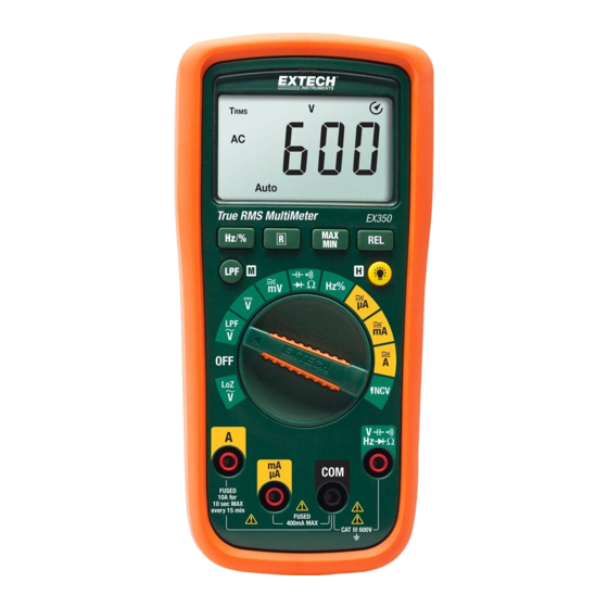
Page 6: Descriptions
3. Descriptions Meter Description (EX350 pictured) Non‐Contact Voltage Detector and LED LCD multi‐function display Manual Range button Hz% button Mode and LPF Button Rotary function select switch 10A input terminal uA and mA input terminal Common (‐) input terminal Positive input terminal: Voltage, Resistance, Capacitance, Temperature (EX355), and µA Data Hold and backlight button REL (RELATIVE) button MAX MIN button *Battery compartment on back of meter Fig 3‐1 METER DESCRIPTION EX35x‐en‐GB_V1.2 12/15 ... - Page 7 Display Icon Descriptions Auto: Automatic range mode HOLD: Display hold : Relative mode AC: Alternating Current Measurements DC: Direct Current Measurements : Main display digits A: Amperes (Current) V: Volts (Voltage) F: Temperature units F: Farads (Capacitance measurement units) Hz: Hertz (Frequency measurements unit) % Duty Cycle (AC only) Ω (Ohms): Resistance measurement unit LPF Variable frequency voltage mode :Battery status icon ‐ Minus (negative) sign MAX‐MIN Peak Maximum and Minimum reading memory : Diode measurement mode : Continuity mode symbol Auto Power Off enabled ...
- Page 8 Push‐Button Descriptions Press the M (MODE) button to perform the following: Switch Position MODE (M) Button Function AC DC (EX355) AC DC AC DC Ω Ω °C °F TEMP (EX355) Press and Hold LPF in the ACV function to select variable frequency tests. Press R (Range) to switch from Auto to Manual Range. Hold to return to Auto Range. Press activates Relative mode. Press to activate Max Min Mode Press to turn HOLD on/off. Press and Hold to turn backlight on/off Press to select Hz or % in AC Voltage or AC Current modes EX35x‐en‐GB_V1.2 12/15 ...
-
Page 9: Operation
4. Operation CAUTION: Read and understand all of the Safety statements listed in the safety section of this manual prior to use. Powering the Meter Turn the rotary function switch to any position to power the meter. Check the batteries if the unit fails to power ON. Refer to the Maintenance section for battery and fuse replacements. Turn the function switch to the OFF position to power OFF the meter. The meter has an Auto Power OFF feature (APO) where the meter switches OFF after 15 minutes of inactivity. When APO is enabled, the APO icon will show on the display when the meter is powered ON. To disable APO, refer to the next section. Disable Auto Power OFF The meter will auto power OFF after 15 minutes of inactivity. To defeat this feature, follow the steps below. With the meter OFF, press and hold the M (MODE) button and, while continuing to hold, turn the rotary function switch to any position to power ON the meter. The meter will beep 5 times. Release the button. APO will now be disabled until the next cycle of power. Display Backlight With the meter powered ON, press and hold the backlight button for two seconds to switch the backlight ON or OFF. Note that excessive use of the backlight will shorten the battery life. When the power supply voltage of the battery falls to 2.6V, the LCD backlight will be faint or unusable; the measurement function can be used normally however. Data Hold To freeze the LCD meter reading, press the H (HOLD) button. While data hold is active, the H display icon appears on the LCD. Press the H button to return to normal operation. The H icon will switch OFF. EX35x‐en‐GB_V1.2 12/15 ... -
Page 10: Voltage Measurements
Voltage Measurements CAUTION: When connecting the test leads to the circuit or device under test, connect the black lead before the red; when removing the test leads, remove the red before the black lead. For safety, be sure to measure a known voltage before using the instrument on an unknown circuit AC Voltage Measurements Insert the black test lead banana plug into the negative (COM) jack and the red test lead banana plug into the positive (V/Ω) jack. Turn the function switch to the or the m position. Press the M button to select AC or DC (EX355 only) The meter defaults to the Auto Range mode (Auto displayed on LCD). Press the R button to access the manual range mode. Press the R button to step through the ranges. Press and hold the R button to return to the Auto Range mode (Auto will be displayed). Touch the test probe tips to the circuit under test. Read the digital value of the measurement in the display. The display will also indicate the proper decimal point and measurement type/units symbols. Use the Hz/% button to view the frequency (Hz) or the duty cycle (%) of the measured voltage % Duty Cycle Note: Duty Cycle measurements are AC only for this meter. Measurement signals must be ‘zero crossing’ and must reach ‐0.7V for the meter to properly display Duty Cycle %. Fig 4‐1 AC VOLTAGE MEASUREMENTS EX35x‐en‐GB_V1.2 12/15 ... - Page 11 DC Voltage Measurements Insert the black test lead banana plug into the negative (COM) jack and the red test lead banana plug into the positive (V/Ω) jack. Move the Function Switch to the or position. Press the M button to select AC or DC Read the Warning and Caution statements at the beginning of this section to determine whether or not to use the test lead probe covers. Touch the test probe tips to the circuit under test. Be sure to observe the correct polarity (red lead to positive, black lead to negative). The meter defaults to the Auto Range mode (Auto displayed on LCD). Press the R button to access the manual range mode. Press the R button to step through the ranges. Press and Hold the R button to return to the Auto Range mode (Auto will be displayed). Read the digital value of the measurement in the display. The display will also indicate the proper decimal point and measurement type/units symbols. If the polarity is reversed, the display will show (‐) minus before the value. The meter is capable of measuring DC voltages to 600V. Fig 4‐2 DC VOLTAGE MEASUREMENTS EX35x‐en‐GB_V1.2 12/15 ...
-
Page 12: A Ac/Dc Current Measurements
10A AC/DC Current Measurements WARNING: Do not handle the test leads above the finger/hand guard barrier. CAUTION: Observe CAT III 600V with respect to Earth Ground. Insert the black test lead into the COM terminal and the red test lead into the A terminal. Turn the meter’s function switch to the position. The A symbol will appear on the display indicating Amperes (Amps). Press the M button to select AC or DC. The meter defaults to the Auto Range mode. When in Auto mode, the display shows the Auto icon. Press the R button to manually range the meter. Press the R button to step through the ranges. Press and Hold the R button to return to the Auto Range mode. Current measurements must be taken in series with the circuit under test. See accompanying diagram. Touch the black test lead to the negative side of the circuit and the red test lead to the positive side of the circuit. Read the current measurement in the display represented by numerical digits and bar graph. The display will indicate the proper decimal point and value. In DC, If the polarity is reversed, the display will show (‐) minus before the value. For AC current, press the Hz/% button to view the frequency (Hz) or the duty cycle (%) of the measured current. % Duty Cycle Note: Duty Cycle measurements are AC only for this meter. Measurement signals must be ‘zero crossing’ and must reach ‐0.7V for the meter to properly display Duty Cycle %. Fig 4‐3 AC/DC 10A CURRENT MEASUREMENTS EX35x‐en‐GB_V1.2 12/15 ... -
Page 13: Ma/Μa Ac/Dc Current Measurements
mA/µA AC/DC Current Measurements WARNING: Do not handle the test leads above the finger/hand guard barrier. CAUTION: Observe CAT III 600V and with respect to Earth Ground. Insert the black test lead into the COM terminal and the red test lead into the mA/µA terminal. Turn the meter’s function switch to the or position. The mA or µA units symbol will appear on the display. The meter defaults to the Auto Range mode. When in Auto mode, the display shows the Auto icon. Press the R button to manually range the meter. Press the R button to step through the ranges. Press and Hold the R button to return to the Auto Range mode. Press the M button to select AC or DC. Current measurements must be taken in series with the circuit under test. See accompanying diagram. Touch the black test lead to the negative side of the circuit and the red test lead to the positive side of the circuit. Read the current measurement in the display represented by the numerical digits and the bar graph. The display will indicate the proper decimal point and value. In DC, If the polarity is reversed, the display will show (‐) minus before the value. Fig 4‐4 mA/µA AC/DC CURRENT MEASUREMENTS EX35x‐en‐GB_V1.2 12/15 ... -
Page 14: Non-Contact Voltage Detector
Non‐Contact Voltage Detector WARNING: It is possible for voltage to be present in a circuit even if the meter does not beep or flash the NCV LED lamp at the top of the meter. Always verify meter operation on a known live AC current circuit and verify that the batteries are fresh before use. The audible beeper sounds and the LED lamp at the top of the meter flashes when the meter senses an electrical voltage field. If the meter does not emit a tone or flash the LED in this mode, there is still the possibility that voltage is present. Please use caution. Turn the function switch to the NCV position to access the Non‐Contact Voltage Detect mode. EF is displayed when in this mode is selected. To test, place the meter near a source of electrical energy. Note that the tip of the meter offers the highest sensitivity. If a voltage is detected, the meter will beep, the NCV LED will flash and one or more “‐“ will appear on the display. For higher detected voltages the beep and flash rate will increase and the number of “‐“ will increase. Fig 4‐5 NON‐CONTACT VOLTAGE DETECTOR EX35x‐en‐GB_V1.2 12/15 ... -
Page 15: Resistance Measurements
Resistance Measurements Cautions: Switch OFF power to the device under test before measuring. Do not test on circuits or devices where 60VDC or 30VAC is present. Insert the black test lead banana plug into the negative (COM) jack. Insert the red test lead banana plug into the positive (V/Ω) jack. Turn the Function Switch to the Ω position. Use the M button to select the Ω icon on the display indicating resistance only (without the audible continuity icon showing). The meter defaults to the Auto Range mode (Auto displayed on LCD). Press the R button to access the manual range mode. Press the R button to step through the ranges. Press and Hold the R button to return to the Auto Range mode (Auto will be displayed). Touch the test probe tips across the circuit or part under test. It is best to disconnect one side of the part under test so the rest of the circuit will not interfere with the resistance reading. Read the resistance value in the display. The display will indicate the proper decimal point and value. If the reading is out of range, the OL display icon will appear. Fig 4‐6 RESISTANCE/CONTINUITY MEASUREMENTS EX35x‐en‐GB_V1.2 12/15 ... -
Page 16: Continuity Measurements
Continuity Measurements Insert the black test lead into the negative COM terminal and the red test lead into the positive terminal. Set the function switch to the position. Use the M button to select the Continuity mode. Look for the Continuity icon on the display. Touch the test probe tips across the wire or circuit under test. The continuity threshold is between 10Ω and 100Ω. For measurements below 10Ω the buzzer will always sound. For measurements above 400Ω (600Ω for EX355) the OL will always display. Capacitance Measurements WARNING: To avoid electric shock, remove power to the circuit under test and discharge the capacitor under test before measuring. Do not test on circuits or devices where 60VDC or 30VAC is present. Set the function switch to the capacitance position. Insert the black test lead banana plug into the negative COM jack and the red test lead banana plug into the positive jack. Press the M button to select the unit of measure symbol F. Touch the test probe tips across the part under test. Read the capacitance value in the display. The display will indicate the proper decimal point and value. Note: For large values of capacitance several seconds may be required before the reading stabilizes. Fig 4‐7 CAPACITANCE MEASUREMENTS EX35x‐en‐GB_V1.2 12/15 ... -
Page 17: Loz Ac Voltage Measurements
LoZ AC Voltage Measurements When the function switch is turned to the Lo Z position, the meter applies a low input impedance circuit to the input terminals to eliminate stray or ghost voltages. Refer to the Voltage Measurements section earlier in this guide for Safety information and connection diagrams. Insert the black test lead banana plug into the negative (COM) jack and the red test lead banana plug into the positive (V/Ω) jack. Move the Function Switch to the Lo‐Z position. Touch the test probe tips to the circuit under test. The meter defaults to the Auto Range mode (Auto displayed on LCD). Manual range cannot be used in this mode. Read the digital value of the measurement in the display. The display will also indicate the proper decimal point and measurement type/units symbols. Variable Frequency Voltage Measurements When the function switch is turned to the LPF position the meter can measure voltage on signals with varying frequency as in Variable Frequency Drives (VFD). Refer to the Voltage Measurements section earlier in this guide for Safety information and connection diagrams. Insert the black test lead banana plug into the negative (COM) jack and the red test lead banana plug into the positive (V/Ω) jack. Move the Function Switch to the LPF position. Select AC voltage Press and Hold the LPF button for two seconds. The meter will beep and the LPF icon will appear on the display. Touch the test probe tips to the circuit under test. The meter defaults to the Auto Range mode. Manual range cannot be used in this mode. Read the digital value of the measurement in the display. The display will also indicate the proper decimal point and measurement type/units symbols. EX35x‐en‐GB_V1.2 12/15 ... -
Page 18: Diode Test
Diode Test Insert the black test lead banana plug into the negative COM jack and the red test lead banana plug into the positive jack. Turn the function switch to position. Use the M button to select the diode function if necessary (the diode and voltage symbols will appear on the LCD when in Diode test mode). Touch the test probe tips to the diode or semiconductor junction under test. Note the meter reading. Reverse the test lead polarity by reversing the red and black leads. Note this reading. The diode or junction can be evaluated as follows: If one reading displays a value (typically 0.400V to 0.900V) and reverse reading displays OL, the diode is good. If both readings display OL the device is open. If both readings are very small or ‘0’, the device is shorted. Fig 4‐8 DIODE TESTING EX35x‐en‐GB_V1.2 12/15 ... -
Page 19: Temperature Measurements (Ex355 Only)
Temperature Measurements (EX355 only) Insert the supplied temperature probe into the COM (‐) and positive (+) terminals observing correct polarity. Turn the function switch to the Temp position. Use the M button to select the desired unit of measure. Touch the temperature probe tip to the device under test or leave the temperature probe in the open air to measure ambient temperature. Read the temperature measurement on the LCD. Fig 4‐9 TEMPERATURE MEASUREMENTS EX35x‐en‐GB_V1.2 12/15 ... -
Page 20: Hz And % Duty Cycle Test
Hz and % Duty Cycle Test Hz and Duty Cycle % are available in the AC Voltage or AC Current functions or can be selected directly in the Hz% position of the function switch. Follow the AC voltage or AC Current procedures for operational details. % Duty Cycle Note: Duty Cycle measurements are AC only for this meter. Measurement signals must be ‘zero crossing’ and must reach ‐0.7V for the meter to properly display Duty Cycle %. Relative Mode This function applies only to Voltage, Current, Temperature and Capacitance modes. In Relative mode a reference reading can be stored with which to compare subsequent readings. Press the REL button to store the displayed reading in memory, this becomes the reference. The symbol will be displayed when the Relative mode is active. Subsequent readings will now be compared to the stored reference (Displayed Reading = Measurement minus Reference). Press ... -
Page 21: Maintenance
5. Maintenance WARNING: To avoid electrical shock, remove the test leads, disconnect the meter from any circuit and turn OFF the meter before opening the case. Do not operate with an open case. Battery and Fuse Replacement Battery Replacement Remove the test leads from the meter. Remove the meter’s protective cover. Remove the Phillips head screw that secures the battery compartment at the back of the meter. Open the battery compartment and replace the two AA batteries observing correct polarity. Re‐assemble the meter before use Safety: Please dispose of batteries responsibly; never dispose of batteries in a fire, batteries may explode or leak. If the meter is not to be used for 60 days or more, remove the battery and store separately. Fig 5‐1 BATTERY AND FUSE REPLACEMENT Fuse Replacement The 600mA fuse can be replaced from the battery compartment. To replace the 10A fuse, remove the four (4) screws that secure the meter housing. Remove the small Phillips screw in the battery compartment. Replace the fuse with one of the same type and rating. Reassemble the meter before use. Never dispose of used batteries or rechargeable batteries in household waste. As consumers, users are legally required to take used batteries to appropriate collection sites, the retail store where the batteries were purchased, or wherever batteries are sold. Disposal: Do not dispose of this instrument in household waste. The user is obligated to take end‐of‐ life devices to a designated collection point for the disposal of electrical and electronic equipment. Cleaning and Storage Periodically wipe the case with a damp cloth and mild detergent; do not use abrasives or solvents. EX35x‐en‐GB_V1.2 12/15 ... -
Page 22: Specifications
6. Specifications ELECTRICAL SPECIFICATIONS Accuracy is given as ± (% of reading + least significant digit) at 23C ±5C with relative humidity lower than 80%. Accuracy is specified for a period of one year after calibration. 1. Temperature Coefficient is 0.1 x specified accuracy / C, < 18C (64.5F), > 28C (82.4F) 2. AC Functionality: ACV and ACA specifications are AC coupled, True RMS, 45 to 400Hz; For non‐sinusoidal waveforms, additional accuracy Crest Factor (C.F.) considerations exist as detailed below: Add 3.0% for C.F. 1.0~2.0; Add 5.0% for C.F. 2.0~2.5; Add 7.0% for C.F. 2.5~3.0 Function Range Resolution Accuracy EX350 EX355 40.00mV 60.00mV 10μV ±(0.7%+5 digits) 400.0mV 600.0mV 0.1mV ±(0.5%+2 digits) DC Voltage 4.000V 6.000V 1mV 40.00V 60.00V 10mV ±(0.5%+3 digits) 400.0V 600.0V 0.1V 600V 600V 1V ... - Page 23 Function Accuracy DC Current Range Resolution EX350 EX355 μA 400.0μA 600.0μA 0.1μA 4000μA 6000μA 1μA ±(0.7%+2 digits) 40.00mA 60.00mA 10μA mA 400.0mA 600.0mA 0.1mA 4.000A 6.000A 1mA ( A ± 1.0%+3 digits) 10.00A 10.00A 10mA Overload protection: μA mA range: (F1) fuse (6.3×32)mm: FF 0.6A H 600V (CE) fast acting 10A range: (F2) fuse (6.3×32)mm: F 10A H 600V (CE) fast acting AC Current Range Resolution Accuracy ...
- Page 24 Capacitance Range Resolution Accuracy In REL mode: 6.000nF 1pF ± (4%+10 digits) 60.00n F to 600.0μF 10pF to 0.1μF ± (4%+5 digits) 6.000mF to 60.00mF 1μF to 10μF ± 10% Overload protection: 600V‐PTC To optimize accuracy, if the measured capacitance is ≤ 1μF use the REL measurement mode 9.999Hz 9.999MHz 0.001Hz 0.001MHz ± (0.1%+5) Frequency ~ 0.1% 99.9% 0.1% Unspecified Duty Cycle Overload protection: 600V‐PTC Input amplitude (a): (DC level is zero) ≤100kHz: 100mVrms≤a≤20Vrms >100kHz~1MHz: 200mVrms≤a≤20Vrms >1MHz: 500mVrms≤a≤20Vrms >5MHz~10MHz: 900mVrms≤ a ≤20Vrms Duty cycle%: Applies to frequency measurements only (≤100kHz) Frequency for Voltage or Current functions: Frequency <1kHz AC voltage: input amplitude of mV range≥100mV, input amplitude of V range≥ the range ×6% ...
- Page 25 GENERAL SPECIFCATIONS Display EX350 4000 count, EX355 6000 count Multi‐Function LCD Over‐range indication “OL” is displayed Conversion rate 2 to 3 updates per second Maximum Voltage 600VAC RMS or 600V DC maximum applied to any terminal Polarity indication Automatic: positive implied, negative indicated (‐) Low battery indication is displayed. Auto Power OFF After 15 minutes (can be disabled by holding the M [MODE] button while turning the meter ON) Operating Temperature and Humidity ‐10~10C (32 to 104F) 0 to 30C (30 to 86F); <75%RH maximum 30 to 40C (86 to 104F); <50%RH maximum Storage Temperature and Humidity ‐10 to 50C (14 to 122F); <80%RH maximum (with battery removed) Operating Altitude 2000m (6562’) Battery power (2) AA batteries (battery life 130 hours typical with alkaline battery types) Fuse protection 10A terminal (F2): F 10A H 600V quick‐break fuse (6.3x32) mm mA, μA terminal (F1): FF 600mA H 600V quick‐break fuse (6.3x32) mm Weight Including battery 407g (14.36oz) Dimensions (W x H x D) 180 x 86 x 55.6 mm (7.1 x 3.4 x 2.2 in.) Safety Standards ...
Need help?
Do you have a question about the EX350 and is the answer not in the manual?
Questions and answers