Extech Instruments EX310 User Manual
Mini multimeter with non-contact voltage detector (ncv)
Hide thumbs
Also See for EX310:
- User manual (17 pages) ,
- User manual (15 pages) ,
- User manual (13 pages)

Subscribe to Our Youtube Channel
Related Manuals for Extech Instruments EX310


Summary of Contents for Extech Instruments EX310
- Page 1 USER MANUAL Mini Multimeter with Non-Contact Voltage Detector (NCV) Model EX310 GlobalTestSupply www. .com Find Quality Products Online at: sales@GlobalTestSupply.com...
-
Page 2: Safety Instructions
Introduction Congratulations on your purchase of the Extech EX310 MultiMeter. The EX310 offers AC/DC Voltage, AC/DC Current, Resistance, Diode, and Continuity testing plus a built-in non-contact Voltage Detector. Proper use and care of this meter will provide many years of reliable service. For copies of this user manual in other languages please visit the website. - Page 3 CAUTIONS Improper use of this meter can cause damage, shock, injury or death. Read and understand this user manual before operating the meter. Always remove the test leads before replacing the battery or fuses. Inspect the condition of the test leads and the meter itself for any damage before operating the meter.
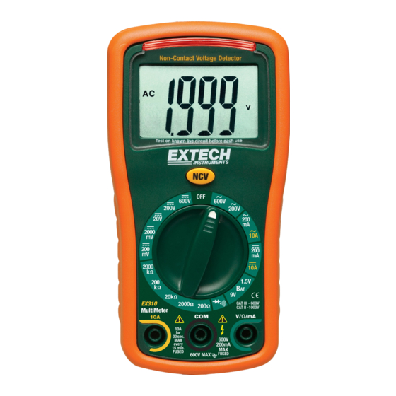
- Page 4 Description 1. AC Voltage Detector Sensor 2. AC Voltage Detector indicator light 3. Display (LCD) 4. Non-contact AC Voltage Detector test button 5. Rotary function dial 6. 10 ampere test lead jack 7. COM test lead jack 8. Test lead jack for voltage, milliamp, resistance/continuity, and diode functions 9.
- Page 5 The reading will stabilize and give a proper measurement when connected to a circuit. NON-CONTACT AC VOLTAGE DETECTOR (NCV) The EX310 can detect the presence of AC voltage (from 100 to 600VAC) simply by being held very near to a voltage source.
-
Page 6: Ac Voltage Measurements
AC VOLTAGE MEASUREMENTS WARNING: Risk of Electrocution. The probe tips may not be long enough to contact the live parts inside some 240V outlets for appliances because the contacts are recessed deep in the outlets. As a result, the reading may show 0 volts when the outlet actually has voltage on it. Make sure the probe tips are touching the metal contacts inside the outlet before assuming that no voltage is present. -
Page 7: Ac / Dc Current Measurements
AC / DC CURRENT MEASUREMENTS CAUTION: Do not make current measurements at 10 Amps for longer than 30 seconds. Exceeding 30 seconds may cause damage to the meter and/or the test leads. Insert the black test lead banana plug into the negative COM jack. For current measurements up to 200mA AC or DC, set the function switch to the 200m AAC or ADC position and insert the red test lead banana plug into the mA jack. -
Page 8: Continuity Check
CONTINUITY CHECK WARNING: To avoid electric shock, never measure continuity on circuits that have a voltage potential. Set the function switch to the position. Insert the black lead banana plug into the negative COM jack. Insert the red test lead banana plug into the positive Ω jack. Touch the test probe tips to the circuit or wire you wish to check. -
Page 9: Maintenance
Maintenance WARNING: To avoid electric shock, disconnect the test leads from any source of voltage before removing the back cover or the battery or fuse covers. WARNING: To avoid electric shock, do not operate your meter until the battery and fuse covers are in place and fastened securely. -
Page 10: Low Battery Indication
BATTERY INSTALLATION and LOW BATTERY INDICATION WARNING: To avoid electric shock, disconnect the test leads from any source of voltage before removing the battery cover. Do not operate meter unless the battery cover is in place. LOW BATTERY INDICATION icon will appear in the lower left-hand corner of the display when the battery voltage becomes low. -
Page 11: Replacing The Fuses
REPLACING THE FUSES WARNING: To avoid electric shock, disconnect the test leads from any source of voltage before removing the fuse cover. Disconnect the test leads from the meter. Remove the protective rubber holster. Remove the Phillips head screw located on the lower back of the instrument. Remove the fuse/battery compartment cover to access the fuses. -
Page 12: General Specifications
General Specifications Diode Test Bias voltage: 2.3VDC Continuity Check Audible signal will sound if the resistance is less than 100 Input Impedance 1MΩ (VDC & VAC) AC Bandwidth 50 / 60Hz Display 2000 count (0 to 1999) LCD Over-range indication “1___”...
Need help?
Do you have a question about the EX310 and is the answer not in the manual?
Questions and answers