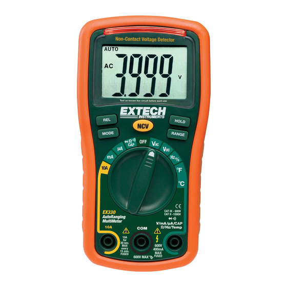
Extech Instruments EX330 User Manual
Mini multimeter with non-contact voltage detector (ncv)
Hide thumbs
Also See for EX330:
- User manual (21 pages) ,
- User manual (18 pages) ,
- User manual (17 pages)

Related Manuals for Extech Instruments EX330


Summary of Contents for Extech Instruments EX330
- Page 1 USER MANUAL Mini Multimeter with Non-Contact Voltage Detector (NCV) Model EX330 Additional User Manual translations available at GlobalTestSupply www. .com Find Quality Products Online at: sales@GlobalTestSupply.com...
-
Page 2: Safety Instructions
Introduction Congratulations on your purchase of the Extech EX330 Meter. The EX330 offers AC/DC Voltage, AC/DC Current, Resistance, Diode, Continuity, non-contact Voltage Detection, Capacitance, Frequency, Duty Cycle, and Temperature (Type K) functions. Proper use and care of this meter will provide many years of reliable service. - Page 3 CAUTIONS • Improper use of this meter can cause damage, shock, injury, or death. Read and understand this user manual before operating the meter. • Always remove the test leads before replacing the battery or fuses. • Inspect the condition of the test leads and the meter itself for any damage before operating the meter.
-
Page 4: Display Symbols And Annunciators
Description AC Voltage Detector Sensor AC Voltage Detector indicator light RELATIVE push-button MODE button Non-contact AC Voltage Detector test button Rotary function dial 10 ampere test lead jack COM test lead jack 10. Test lead jack for voltage, milli-amp, micro-amp, resistance, capacitance, frequency, and temperature functions 11. - Page 5 NON-CONTACT AC VOLTAGE DETECTOR (NCV) The EX330 can detect the presence of AC voltage (from 100 to 600VAC) simply by being held very near to a voltage source. WARNING: Test the AC voltage detector on a known live circuit before each use.
-
Page 6: Ac Voltage Measurements
AC VOLTAGE MEASUREMENTS WARNING: Risk of Electrocution. The probe tips may not be long enough to contact the live parts inside some 240V outlets for appliances because the contacts are recessed deep in the outlets. As a result, the reading may show 0 volts when the outlet actually has voltage on it. Make sure the probe tips are touching the metal contacts inside the outlet before assuming that no voltage is present. -
Page 7: Ac / Dc Current Measurements
AC / DC CURRENT MEASUREMENTS CAUTION: Do not make current measurements at 10 Amps for longer than 30 seconds. Exceeding 30 seconds may cause damage to the meter and/or the test leads. Insert the black test lead banana plug into the negative COM jack. For current measurements up to 4000µA, set the function switch to the µA position and insert the red test lead banana plug into the mA/µA jack For current measurements up to 400mA, set the function switch to the mA position and insert... -
Page 8: Continuity Check
CONTINUITY CHECK WARNING: To avoid electric shock, never measure continuity on circuits or wires that have voltage on them. Set the function switch to the position. Insert the black lead banana plug into the negative COM jack. Insert the red test lead banana plug into the positive Ω jack. Use the MODE button to view the icon on the display. -
Page 9: Frequency Measurements
FREQUENCY MEASUREMENTS Use the MODE button to view the Hz unit of measure on the LCD display. Insert the black test lead banana plug into the negative COM jack and the red test lead banana plug into the positive Hz jack. Touch the test probe tips to the circuit under test. -
Page 10: Relative Mode
RELATIVE MODE The relative measurement feature allows you to make measurements relative to a stored reference value. A reference voltage, current, etc. can be stored so that subsequent measurements can be made in comparison to that value. The displayed value is the difference between the reference value and the measured value. -
Page 11: Low Battery Indication
BATTERY INSTALLATION and LOW BATTERY INDICATION WARNING: To avoid electric shock, disconnect the test leads from any source of voltage before removing the battery cover. LOW BATTERY INDICATION icon will appear in the lower left-hand corner of the display when the battery voltage becomes low. -
Page 12: Replacing The Fuses
REPLACING THE FUSES WARNING: To avoid electric shock, disconnect the test leads from any source of voltage before removing the fuse cover. Disconnect the test leads from the meter. Remove the protective rubber holster as shown in the diagram. Remove the Phillips head screw located on the lower back of the instrument. Flip up the fuse/battery compartment cover to access the fuses. - Page 13 ±(1.2% reading + 4 digits) Resistance 400Ω 0.1Ω 4kΩ 1Ω 40kΩ 0.01kΩ ±(1.2% reading + 2 digits) 400kΩ 0.1kΩ 4MΩ 0.001MΩ ±(2.0% reading + 3 digits) 40MΩ 0.01MΩ ±(3.5% reading + 40 digits) 0.001nF Capacitance 40nF 0.01nF ±(2.5% reading + 4 digits) 400nF 0.1nF 4µF...
-
Page 14: General Specifications
General Specifications Diode Test Test current: 0.3mA max., Open circuit voltage: 1.5V DC typ. Continuity Check Audible signal will sound if the resistance is less than 35Ω Temperature Sensor Requires Type-K thermocouple 10MΩ (VDC & VAC) Input Impedance AC Bandwidth 50 / 60Hz Display 4000 count (0 to 3999 digits) LCD... -
Page 15: Two Year Warranty
Two-year Warranty Teledyne FLIR warrants this Extech brand instrument to be free of defects in parts and workmanship for two years from date of shipment (a six-month limited warranty applies to sensors and cables). To view the full warranty text please visit: Calibration and Repair Services Teledyne FLIR offers calibration and repair services for the Extech brand products we sell.
Need help?
Do you have a question about the EX330 and is the answer not in the manual?
Questions and answers